DP83848T-MAU-EK Purpose and Contents
The purpose of the DP83848T-MAU-EK (EK) is to provide National Semiconductor Corp.'s
customers with a vehicle to quickly design and market systems containing the DP83848T chip.
Customers are encouraged to copy EK components to expedite their design process.
The EK contains:
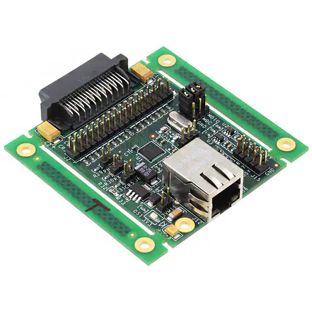
• DP83848T Media Attachment Unit (MAU)
• Printed copy of this User's Guide
• DP83848T MAU schematic
• DP83848T MAU licensing agreement
Information and Specifications
This section contains specifications of the DP83848T MAU card, as well as a description of the
card's interfaces, connectors, jumpers and the LED.
Usage setup and configuration
Power for the DP83848T MAU is supplied via MII connector.
• If 5V is supplied, the on-board voltage regulator, U5, will convert 5V to 3.3V for the device.
J11 should be removed.
• If 3.3V is supplied from the MII connector, J11 needs to be ON (See schematics for details).
Address settings:
The PMD address for the DP83848T Physical Layer device is set by jumper J4.
• Default board setting for the PHY Address is 01
• The board may be set to PHY Address 03 by adding jumper J4.
Table of jumpers:
Jumper
J1
J2
J3A,B,C
Name
MII Male
Connector
MII Header
MDIO access
J4
PHYAD1
J5
J6
MDIX_EN
LED_CFG
J7
J8 (Not
populated)
J9
J11
RESET_N
Optional header
MII 3V3 option
J12
J15
Pulse Jack
MDIO connector
Function
MII interface
Alternative connection for MII signals
J3 A to B should be ON for MII MDIO access, J3B to C should ON for
on_board uMDIO access, J3 A, B, C should be OFF for external
uMDIO/FDI card use
PHY Address strap pin (PHY address = 01 when J4 is OFF, PHY address
= 03 when J4 is ON)
Auto_MDIX is enabled when J5 is OFF and disabled when J5 is ON.
Set LED configuration. When J6 is OFF and the chip is powered, a light on
LED_LNK represents the presence of a link. When J6 is ON, the blinking
light on LED_LNK represents link and activity. In both cases when there is
no light on LED_LNK, this is an indication of absence of link.
J7 ON will reset the device
J11 should OFF for 5V MII supply and J11 should be ON for 3.3V MII
supply
Integrated Magnetic RJ-45 connector
On_board uMDIO connection
National Semiconductor Corporation
www.national.com
�DP83848T MAU Specification
Overview
The DP83848T MAU is an NSC demo platform to allow customer evaluation of our device.
While the DP83848T has many advanced and enticing features, this specific board is designed to
demonstrate only a subset of those. The features chosen are the ones that the mainstream
customers will use. Thus we have created an affordable, aesthetic platform to demonstrate the
simplicity of designing in a National Semiconductor DP83848T.
Target Environment
Any customer equipment that provides a standard IEEE 802.3, Clause 22 MII DTE interface; e.g.
SmartBits/Netcom box.
Features/Goals
The DP83848T MAU features:
• Intergrated magnetics
• Minimum configuration requirements:
o 2 PHY Addresses - 01h (default) or 03h
o 2 LEDs – 1 power, 1 LED for LINK
o Strap Options – MDIX_EN, LED_CFG
o RESET_N jumper
• Connections for the following interfaces:
o MIl Interface
o Integrated transformer RJ-45
o Header for “ribbon cable” connection to MII
• Standard PCB layout considerations with regards to clock, MII, and TD/RD
• Single sided component placement
• On-board clock – Crystal
• On-board power supplied by MII connector only, jumper to configure 5v or 3.3v
• On-board MDIO circuit
• Low cost
National Semiconductor Corporation
www.national.com
�MAU Block Diagram
Serial
Management
(uMDIO)
MII
25MHz
Xtal
DP83848T
PHYAD
strap
LED_CFG
Strap
Reset
Integrated
Magnetic
RJ-45
MDIX_EN
strap
PCB Physical Layout requirements / Considerations
•
•
•
•
•
•
•
•
•
FR4 material
Trace impedance will be ensured by design:
o Trace symmetry within differential pair (+/- 0.5”)
o Differential impedance 100 ohms, +/- 5%
o Adjacent differential pairs spacing > 2X distance within a differential pair, to
minimize cross-talk and EMI
Trace length matching between differential pairs not required
Trace space will be 0.007”/0.008” minimum
Uniform supply & ground plane
Combination of through-hole and surface mount technology
Target size 2.0” (height), 3.0” (length)
4 layers
Silk screen on two sides
MAU Interface requirements
•
•
•
System interface will be via the MII connector, and MII header
RJ-45 for network connection
On Board Serial Management circuit
Software
•
No device specific software is required for this board
National does provide the integrity utility; a diagnostic and configuration package at
www.national.com/appinfo/networks/ethernet_utility.html
Additional information
Updated versions of the included material, related material can be found by going to
ethernet.national.com or directly to design resources at
http://www.national.com/appinfo/networks/webench/dp83848.html
National Semiconductor Corporation
www.national.com
�National Semiconductor Corporation
2900 Semiconductor Drive
Santa Clara, CA 95051, U.S.A.
Tel: 1-800-272-9959
Fax: 1-800-737-7018
Email: support@nsc.com
WWW: www.national.com
National Semiconductor Europe
Fax: (+49) 0-180-530 85 86
Email: europe.support@nsc.com
Deutsch Tel: (+49) 0-180-530 85 85
English Tel: (+49) 0-180-532 78 32
National Semiconductor Asia Pacific
Customer Response Group
Tel: 65-254-4466
Fax: 65-250-4466
Email: sea.support@nsc.com
National Semiconductor Japan Ltd.
Tel: 81-3-5620-6175
Fax: 81-3-5620-6179
Copyright © 2005 National Semiconductor Corporation.
National Semiconductor and the National Semiconductor logo are registered trademarks of National Semiconductor Corporation.
All other brand or product names are trademarks of their respective holders.
National Semiconductor Corporation
www.national.com
�IMPORTANT NOTICE
Texas Instruments Incorporated and its subsidiaries (TI) reserve the right to make corrections, modifications, enhancements, improvements,
and other changes to its products and services at any time and to discontinue any product or service without notice. Customers should
obtain the latest relevant information before placing orders and should verify that such information is current and complete. All products are
sold subject to TI’s terms and conditions of sale supplied at the time of order acknowledgment.
TI warrants performance of its hardware products to the specifications applicable at the time of sale in accordance with TI’s standard
warranty. Testing and other quality control techniques are used to the extent TI deems necessary to support this warranty. Except where
mandated by government requirements, testing of all parameters of each product is not necessarily performed.
TI assumes no liability for applications assistance or customer product design. Customers are responsible for their products and
applications using TI components. To minimize the risks associated with customer products and applications, customers should provide
adequate design and operating safeguards.
TI does not warrant or represent that any license, either express or implied, is granted under any TI patent right, copyright, mask work right,
or other TI intellectual property right relating to any combination, machine, or process in which TI products or services are used. Information
published by TI regarding third-party products or services does not constitute a license from TI to use such products or services or a
warranty or endorsement thereof. Use of such information may require a license from a third party under the patents or other intellectual
property of the third party, or a license from TI under the patents or other intellectual property of TI.
Reproduction of TI information in TI data books or data sheets is permissible only if reproduction is without alteration and is accompanied
by all associated warranties, conditions, limitations, and notices. Reproduction of this information with alteration is an unfair and deceptive
business practice. TI is not responsible or liable for such altered documentation. Information of third parties may be subject to additional
restrictions.
Resale of TI products or services with statements different from or beyond the parameters stated by TI for that product or service voids all
express and any implied warranties for the associated TI product or service and is an unfair and deceptive business practice. TI is not
responsible or liable for any such statements.
TI products are not authorized for use in safety-critical applications (such as life support) where a failure of the TI product would reasonably
be expected to cause severe personal injury or death, unless officers of the parties have executed an agreement specifically governing
such use. Buyers represent that they have all necessary expertise in the safety and regulatory ramifications of their applications, and
acknowledge and agree that they are solely responsible for all legal, regulatory and safety-related requirements concerning their products
and any use of TI products in such safety-critical applications, notwithstanding any applications-related information or support that may be
provided by TI. Further, Buyers must fully indemnify TI and its representatives against any damages arising out of the use of TI products in
such safety-critical applications.
TI products are neither designed nor intended for use in military/aerospace applications or environments unless the TI products are
specifically designated by TI as military-grade or "enhanced plastic." Only products designated by TI as military-grade meet military
specifications. Buyers acknowledge and agree that any such use of TI products which TI has not designated as military-grade is solely at
the Buyer's risk, and that they are solely responsible for compliance with all legal and regulatory requirements in connection with such use.
TI products are neither designed nor intended for use in automotive applications or environments unless the specific TI products are
designated by TI as compliant with ISO/TS 16949 requirements. Buyers acknowledge and agree that, if they use any non-designated
products in automotive applications, TI will not be responsible for any failure to meet such requirements.
Following are URLs where you can obtain information on other Texas Instruments products and application solutions:
Products
Applications
Audio
www.ti.com/audio
Automotive and Transportation www.ti.com/automotive
Amplifiers
amplifier.ti.com
Communications and Telecom www.ti.com/communications
Data Converters
dataconverter.ti.com
Computers and Peripherals
www.ti.com/computers
DLP® Products
www.dlp.com
Consumer Electronics
www.ti.com/consumer-apps
DSP
dsp.ti.com
Energy and Lighting
www.ti.com/energy
Clocks and Timers
www.ti.com/clocks
Industrial
www.ti.com/industrial
Interface
interface.ti.com
Medical
www.ti.com/medical
Logic
logic.ti.com
Security
www.ti.com/security
Power Mgmt
power.ti.com
Space, Avionics and Defense
www.ti.com/space-avionics-defense
Microcontrollers
microcontroller.ti.com
Video and Imaging
www.ti.com/video
RFID
www.ti-rfid.com
OMAP Mobile Processors
www.ti.com/omap
Wireless Connectivity
www.ti.com/wirelessconnectivity
TI E2E Community Home Page
e2e.ti.com
Mailing Address: Texas Instruments, Post Office Box 655303, Dallas, Texas 75265
Copyright © 2012, Texas Instruments Incorporated
�


 工商网监
湘ICP备2023018690号
工商网监
湘ICP备2023018690号
