DRV2700EVM
Quick-Start Guide
➔
Start Here
ti.com/drv2700
2015
�Getting Started
The DRV2700EVM comes with preprogrammed firmware to provide a
0- to 200-Vpp signal between OUT+ and OUT–.
1. Out of the box, the jumpers are set to begin demo mode using USB power.
The default jumper settings are found in the table below.
2. Connect a mini-USB cable to the USB connector on the DRV2700EVM board.
3. Connect the other end of the USB cable to an available USB port on a computer,
USB charger, or USB battery pack.
4. If the board is powered correctly, the 5-V LED is on.
5. Enable the output using the GUI or programmatically through the computer,
see GUI Interface for additional assistance. If using an external input signal,
EN the output by changing the jumper (JP9) or equivalent control signal.
6. Once the output is EN, the device allows for the high-voltage output.
Parameter
Jumper Setting
Default
Open
JP10 MSP
MSP not connected to either power supply
USB (top) (1)
4
VIN (bottom)
DRV2700 not connected to either power supply
USB (top) (1)
DRV2700 connected to USB power supply
VIN (bottom)
JP5 and
JP6
Open
JP9-EN
JP8-G1
JP7-G0
Open
JP13-DCIN
JP12-VBST
I2C
J2, J3, J4
(1)
(1)
4
DRV2700 connected to VIN power supply
Disconnected PWM± and I/O of MSP430
Connected
4
Connected PWM± and I/O of MSP430
EN/G1/G0 pulled internally to GND
MSP (top) (1)
PU (bottom)
MSP connected to USB power supply
MSP connected to VIN power supply
(1)
Open
JP11 DRV
Specification
4
Open
EN/G1/G0 tied to I/O of MSP430
EN/G1/G0 pulled up to MSP power supply
(1)
4
DC input not connected (PWM and AC input mode)
Connected
DC input connected (single ended input mode)
Open
PVDD disconnected to VBST (boost only mode)
Connected
4
PVDD connected to VBST (normal operation)
Open
Always leave open. Never jumper together.
Open
Disconnects particular FB resistor (lowers VBST)
Connected
4
Connects particular FB resistor (raises VBST)
In the table, (top) or (bottom) means the (top) or (bottom) is connected to the middle of the 3-terminal header.
DRV2700 Quick Start Guide
2
Texas Instruments 2015
�DRV2700 Quick Start Guide
3
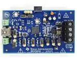
Power Path Selection
External Power
USB Power
Analog Input
MSP
DRV
MSP430
Single Ended
Input
DRV2700
Gain Config
HIGH VOLTAGE
HIGH VOLTAGE
Boost Voltage Config
DRV2700EVM
AIP037A
For evaluation only not FCC approved for resale
EN Config
!
Used for MSP430
Programmation
Outputs
VBoost Disconnect
Quick Reference Board Diagram
Texas Instruments 2015
�Design Resources and References
TM
E2E Haptic Forum
ti.com/hapticforum
Available on ti.com/drv2700
• DRV2700 datasheet
• Complete DRV2700EVM User’s Guide
• Schematics and layout
• EVM source code and binaries
Get more information on TI’s solutions for touch feedback-enabled
applications at ti.com/haptics
• Watch videos
• Compare products
• Find companion products
• Download software
• Order samples and EVMs
Important Notice: The products and services of Texas Instruments Incorporated and its subsidiaries described herein are
sold subject to TI’s standard terms and conditions of sale. Customers are advised to obtain the most current and complete
information about TI products and services before placing orders. TI assumes no liability for applications assistance,
customer’s applications or product designs, software performance, or infringement of patents. The publication of
information regarding any other company’s products or services does not constitute TI’s approval, warranty, or
endorsement thereof.
The platform bar, E2E, MSP430 and WEBENCH are trademarks of Texas Instruments.
All other trademarks are the property of their respective owners.
© 2015 Texas Instruments Incorporated
Printed in the U.S.A.
SLYU023
�IMPORTANT NOTICE
Texas Instruments Incorporated and its subsidiaries (TI) reserve the right to make corrections, enhancements, improvements and other
changes to its semiconductor products and services per JESD46, latest issue, and to discontinue any product or service per JESD48, latest
issue. Buyers should obtain the latest relevant information before placing orders and should verify that such information is current and
complete. All semiconductor products (also referred to herein as “components”) are sold subject to TI’s terms and conditions of sale
supplied at the time of order acknowledgment.
TI warrants performance of its components to the specifications applicable at the time of sale, in accordance with the warranty in TI’s terms
and conditions of sale of semiconductor products. Testing and other quality control techniques are used to the extent TI deems necessary
to support this warranty. Except where mandated by applicable law, testing of all parameters of each component is not necessarily
performed.
TI assumes no liability for applications assistance or the design of Buyers’ products. Buyers are responsible for their products and
applications using TI components. To minimize the risks associated with Buyers’ products and applications, Buyers should provide
adequate design and operating safeguards.
TI does not warrant or represent that any license, either express or implied, is granted under any patent right, copyright, mask work right, or
other intellectual property right relating to any combination, machine, or process in which TI components or services are used. Information
published by TI regarding third-party products or services does not constitute a license to use such products or services or a warranty or
endorsement thereof. Use of such information may require a license from a third party under the patents or other intellectual property of the
third party, or a license from TI under the patents or other intellectual property of TI.
Reproduction of significant portions of TI information in TI data books or data sheets is permissible only if reproduction is without alteration
and is accompanied by all associated warranties, conditions, limitations, and notices. TI is not responsible or liable for such altered
documentation. Information of third parties may be subject to additional restrictions.
Resale of TI components or services with statements different from or beyond the parameters stated by TI for that component or service
voids all express and any implied warranties for the associated TI component or service and is an unfair and deceptive business practice.
TI is not responsible or liable for any such statements.
Buyer acknowledges and agrees that it is solely responsible for compliance with all legal, regulatory and safety-related requirements
concerning its products, and any use of TI components in its applications, notwithstanding any applications-related information or support
that may be provided by TI. Buyer represents and agrees that it has all the necessary expertise to create and implement safeguards which
anticipate dangerous consequences of failures, monitor failures and their consequences, lessen the likelihood of failures that might cause
harm and take appropriate remedial actions. Buyer will fully indemnify TI and its representatives against any damages arising out of the use
of any TI components in safety-critical applications.
In some cases, TI components may be promoted specifically to facilitate safety-related applications. With such components, TI’s goal is to
help enable customers to design and create their own end-product solutions that meet applicable functional safety standards and
requirements. Nonetheless, such components are subject to these terms.
No TI components are authorized for use in FDA Class III (or similar life-critical medical equipment) unless authorized officers of the parties
have executed a special agreement specifically governing such use.
Only those TI components which TI has specifically designated as military grade or “enhanced plastic” are designed and intended for use in
military/aerospace applications or environments. Buyer acknowledges and agrees that any military or aerospace use of TI components
which have not been so designated is solely at the Buyer's risk, and that Buyer is solely responsible for compliance with all legal and
regulatory requirements in connection with such use.
TI has specifically designated certain components as meeting ISO/TS16949 requirements, mainly for automotive use. In any case of use of
non-designated products, TI will not be responsible for any failure to meet ISO/TS16949.
Products
Applications
Audio
www.ti.com/audio
Automotive and Transportation
www.ti.com/automotive
Amplifiers
amplifier.ti.com
Communications and Telecom
www.ti.com/communications
Data Converters
dataconverter.ti.com
Computers and Peripherals
www.ti.com/computers
DLP® Products
www.dlp.com
Consumer Electronics
www.ti.com/consumer-apps
DSP
dsp.ti.com
Energy and Lighting
www.ti.com/energy
Clocks and Timers
www.ti.com/clocks
Industrial
www.ti.com/industrial
Interface
interface.ti.com
Medical
www.ti.com/medical
Logic
logic.ti.com
Security
www.ti.com/security
Power Mgmt
power.ti.com
Space, Avionics and Defense
www.ti.com/space-avionics-defense
Microcontrollers
microcontroller.ti.com
Video and Imaging
www.ti.com/video
RFID
www.ti-rfid.com
OMAP Applications Processors
www.ti.com/omap
TI E2E Community
e2e.ti.com
Wireless Connectivity
www.ti.com/wirelessconnectivity
Mailing Address: Texas Instruments, Post Office Box 655303, Dallas, Texas 75265
Copyright © 2015, Texas Instruments Incorporated
�