Product
Folder
Order
Now
Support &
Community
Tools &
Software
Technical
Documents
DRV3201-Q1
SLVSE98 – JULY 2017
DRV3201-Q1 3 Phase Motor Driver-IC for Automotive Safety Applications
1 Features
2 Applications
•
•
•
•
•
•
•
•
•
•
•
•
•
•
•
•
•
•
•
•
•
3 Description
The bridge driver is dedicated to automotive 3 phase
brushless DC motor control including safety relevant
applications. It provides six dedicated drivers for
normal level N-Channel MOSFET transistors. The
driver capability is designed to handle gate charges
of 250 nC, and the driver source/sink currents are
programmable for easy output slope adjustment. The
device also incorporates sophisticated diagnosis,
protection and monitoring features through an SPI
interface. A boost converter with integrated FET
provides the overdrive voltage, allowing full control on
the power-stages even for low battery voltage down
to 4.75 V.
Device Information(1)
PART NUMBER
DRV3201-Q1
PACKAGE
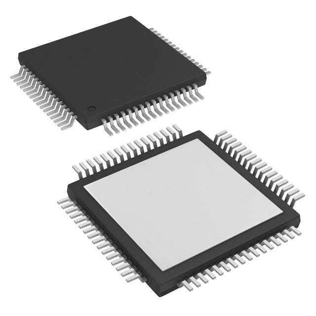
HTQFP (64)
BODY SIZE (NOM)
10.00 mm × 10.00 mm
(1) For all available packages, see the orderable addendum at
the end of the data sheet.
Typical Application Diagram
Battery Voltage
BOOST
•
Automotive Safety Critical Motor-Control
Applications
– Electrical Power Steering (EPS, EHPS)
– Electrical Brake/Brake Assist
– Transmission
– Oil-Pump
Industrial Safety Critical Motor-Control
Applications
SW
•
•
Qualified for Automotive Applications
AEC-Q100 Test Guidance With the Following
Results:
– Device Temperature Grade 1: –40°C to 125°C
Ambient Operating Temperature
– Device HBM ESD Classification Level 2
– Device CDM ESD Classification Level C3
3 Phase Bridge Driver for Motor Control
Drives 6 Separate N-Channel Power MOSFETs
up to 250-nC Gate Charge
Programmable 140-mA to 1-A Gate Current Drive
(Source/Sink) for Easy Output Slope Adjustment
–7-V to 40-V Compliance on All FET Driver Pins
to Handle Inductive Undershooting and
Overshooting
Separate Control Input for Each Power MOSFET
PWM Frequency up to 30 kHz
Supports 100% Duty Cycle Operation
Operating Voltage: 4.75 to 30 V
Proper Low Supply Voltage Operation Due to
Integrated Boost Converter for Gate-Driver
Voltage Generation
Logic Functional Down to 3 V
Short Circuit Protection With VDS-Monitoring and
Adjustable Detection Level
Two Integrated High Accuracy Current Sense
Amplifiers With Two Gain-Programmable Second
Stage for Higher Resolution at Low Load Current
Operation
Overvoltage and Undervoltage Protection
Shoot-Through Protection With Programmable
Dead Time
Three Real Time Phase Comparators
Overtemperature Warning and Shut Down
Sophisticated Failure Detection and Handling
Through SPI Interface
Sleep Mode Function
Reset and Enable Function
Package: 64-pin HTQFP PowerPAD™
VS
1
Boost Converter
B_EN
Controller
3 × Phase Comp
GNDLS_B
PHxC
ERR
SPI
RSTN
EN
Control Logic
and
Safety / Diagnostic
3 Phase Gate Driver
3 × PowerStage
GHSx
SHSx
IHSx, ILSx
DRVOFF
VCC5
ADREF
BLDC
Motor
GLSx
VCC3
Internal
Supply
RI
Shift Buffer
SLSx
x = 1..3
2 × 2nd Current Sense Amp
RO
2 × 1st Current Sense Amp
IPy
O3,4
2 × Current Shunt
O1,2
INy
y = 1..2
1
An IMPORTANT NOTICE at the end of this data sheet addresses availability, warranty, changes, use in safety-critical applications,
intellectual property matters and other important disclaimers. PRODUCTION DATA.
�DRV3201-Q1
SLVSE98 – JULY 2017
www.ti.com
4 Device and Documentation Support
4.1 Documentation Support
4.1.1 Related Documentation
For related documentation see the following:
• DRV3201 Boost Converter
• DRV3201 Current Sense Amplifier
• DRV3201EVM
• PowerPAD™ Thermally Enhanced Package
4.2 Receiving Notification of Documentation Updates
To receive notification of documentation updates, navigate to the device product folder on ti.com. In the upper
right corner, click on Alert me to register and receive a weekly digest of any product information that has
changed. For change details, review the revision history included in any revised document.
4.3 Community Resources
The following links connect to TI community resources. Linked contents are provided "AS IS" by the respective
contributors. They do not constitute TI specifications and do not necessarily reflect TI's views; see TI's Terms of
Use.
TI E2E™ Online Community TI's Engineer-to-Engineer (E2E) Community. Created to foster collaboration
among engineers. At e2e.ti.com, you can ask questions, share knowledge, explore ideas and help
solve problems with fellow engineers.
Design Support TI's Design Support Quickly find helpful E2E forums along with design support tools and
contact information for technical support.
4.4 Trademarks
PowerPAD, E2E are trademarks of Texas Instruments.
All other trademarks are the property of their respective owners.
4.5 Electrostatic Discharge Caution
These devices have limited built-in ESD protection. The leads should be shorted together or the device placed in conductive foam
during storage or handling to prevent electrostatic damage to the MOS gates.
4.6 Glossary
SLYZ022 — TI Glossary.
This glossary lists and explains terms, acronyms, and definitions.
5 Mechanical, Packaging, and Orderable Information
The following pages include mechanical, packaging, and orderable information. This information is the most
current data available for the designated devices. This data is subject to change without notice and revision of
this document. For browser-based versions of this data sheet, refer to the left-hand navigation.
2
Submit Documentation Feedback
Copyright © 2017, Texas Instruments Incorporated
Product Folder Links: DRV3201-Q1
�PACKAGE OPTION ADDENDUM
www.ti.com
10-Dec-2020
PACKAGING INFORMATION
Orderable Device
Status
(1)
Package Type Package Pins Package
Drawing
Qty
Eco Plan
(2)
Lead finish/
Ball material
MSL Peak Temp
Op Temp (°C)
Device Marking
(3)
(4/5)
(6)
DRV3201QPAPQ1
ACTIVE
HTQFP
PAP
64
160
RoHS & Green
NIPDAU
Level-3-260C-168 HR
-40 to 125
DRV3201
DRV3201QPAPRQ1
ACTIVE
HTQFP
PAP
64
1000
RoHS & Green
NIPDAU
Level-3-260C-168 HR
-40 to 125
DRV3201
(1)
The marketing status values are defined as follows:
ACTIVE: Product device recommended for new designs.
LIFEBUY: TI has announced that the device will be discontinued, and a lifetime-buy period is in effect.
NRND: Not recommended for new designs. Device is in production to support existing customers, but TI does not recommend using this part in a new design.
PREVIEW: Device has been announced but is not in production. Samples may or may not be available.
OBSOLETE: TI has discontinued the production of the device.
(2)
RoHS: TI defines "RoHS" to mean semiconductor products that are compliant with the current EU RoHS requirements for all 10 RoHS substances, including the requirement that RoHS substance
do not exceed 0.1% by weight in homogeneous materials. Where designed to be soldered at high temperatures, "RoHS" products are suitable for use in specified lead-free processes. TI may
reference these types of products as "Pb-Free".
RoHS Exempt: TI defines "RoHS Exempt" to mean products that contain lead but are compliant with EU RoHS pursuant to a specific EU RoHS exemption.
Green: TI defines "Green" to mean the content of Chlorine (Cl) and Bromine (Br) based flame retardants meet JS709B low halogen requirements of
很抱歉,暂时无法提供与“DRV3201QPAPQ1”相匹配的价格&库存,您可以联系我们找货
免费人工找货- 国内价格 香港价格
- 1+115.644611+14.98003
- 10+91.0501510+11.79418
- 25+84.9046825+10.99813
- 160+76.39100160+9.89531