User's Guide
SLVU811C – June 2013 – Revised October 2018
DRV8711EVM User’s Guide
This document is provided with the DRV8711 customer evaluation module (EVM) as a supplement to the
DRV8711 datasheet. It details the hardware implementation of the EVM.
1
2
3
4
5
6
Contents
PCB (Top View) .............................................................................................................. 3
Introduction to PCB .......................................................................................................... 3
2.1
Connectors .......................................................................................................... 3
2.2
Test Points ........................................................................................................... 4
2.3
Jumpers .............................................................................................................. 4
2.4
Motor Outputs ....................................................................................................... 5
GUI Software Installation ................................................................................................... 6
3.1
System Requirements .............................................................................................. 6
3.2
Installation Procedure .............................................................................................. 6
DRV8711 EVM GUI Overview ............................................................................................ 18
4.1
Pages in GUI ....................................................................................................... 18
4.2
High Level Page ................................................................................................... 19
4.3
Menu Options ...................................................................................................... 27
Operating the EVM ......................................................................................................... 31
5.1
Schematic .......................................................................................................... 33
Bill of Materials ............................................................................................................. 36
List of Figures
1
Connections .................................................................................................................. 4
2
Jumpers ....................................................................................................................... 5
3
Motor Outputs ................................................................................................................ 6
4
Setup_DRV8711_EVM.exe................................................................................................. 7
5
Installation Initialization
6
7
8
9
10
11
12
13
14
15
16
17
18
19
20
21
..................................................................................................... 7
License Agreement .......................................................................................................... 8
National Instruments License Agreement ................................................................................ 8
Installation Directory ......................................................................................................... 9
Component Selection ...................................................................................................... 10
Configure Proxy ............................................................................................................ 11
Ready to Install ............................................................................................................. 11
Downloading RTE .......................................................................................................... 12
LabVIEW RTE Self Extraction ............................................................................................ 12
LabVIEW RTE Installation Initialization ................................................................................. 13
Installation of LabVIEW RTE in Progress ............................................................................... 13
FTDI Installation Initialization ............................................................................................. 14
Driver Installation Wizard.................................................................................................. 14
License Agreement for FTDI ............................................................................................. 15
Driver Installation Completion ............................................................................................ 15
Installation Complete ...................................................................................................... 16
Customize Python 2.7.8 window ......................................................................................... 17
SLVU811C – June 2013 – Revised October 2018
Submit Documentation Feedback
Copyright © 2013–2018, Texas Instruments Incorporated
DRV8711EVM User’s Guide
1
�www.ti.com
22
23
24
25
26
27
28
29
30
31
32
33
34
35
36
37
38
39
40
41
42
43
44
45
46
2
..........................................................................................
DRV8711 EVM Screen ....................................................................................................
Control Signals .............................................................................................................
Motion Control Frame .....................................................................................................
Acceleration Profile ........................................................................................................
Motor Control Examples ...................................................................................................
Configuration Tab ..........................................................................................................
Current Regulation Tab....................................................................................................
PWM Control................................................................................................................
Low-Level Configuration Page ...........................................................................................
Update Mode ...............................................................................................................
Register Level Value Page................................................................................................
Field Level Value Change .................................................................................................
Bit Level Value Change ...................................................................................................
Low Level Page Operations ..............................................................................................
File Menu ....................................................................................................................
Script Menu .................................................................................................................
Launch Macro...............................................................................................................
Start Recording .............................................................................................................
Stop Recording .............................................................................................................
Debug Menu ................................................................................................................
About Page..................................................................................................................
Wake the Device ...........................................................................................................
Turn the Motor ..............................................................................................................
Stop the Motor ..............................................................................................................
Python Script Directory Update
DRV8711EVM User’s Guide
17
18
19
19
20
21
22
23
24
25
25
26
26
26
27
27
28
29
29
30
30
31
32
32
32
SLVU811C – June 2013 – Revised October 2018
Submit Documentation Feedback
Copyright © 2013–2018, Texas Instruments Incorporated
�PCB (Top View)
www.ti.com
1
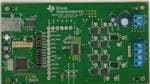
PCB (Top View)
2
Introduction to PCB
The DRV8711EVM is a complete solution for evaluating the DRV8711 stepper motor controller. It includes
a MSP430F2617 to control the DRV8711. Power is provided externally, up to 52 V, through the power
header. The USB interface is provided to communicate with the MSP430F2617 through a graphical user
interface (GUI).
The DRV8711EVM is configured such that only connections to the universal serial bus (USB), motor and
power supply are required.
2.1
Connectors
The DRV8711EVM uses a combination of headers for the application and monitoring of power. For the
EVM, a single power supply rail is necessary. The minimum recommended input voltage (VM+) for the
EVM is 8 V and the maximum recommended input voltage is 52 V. Please see the DRV8711 datasheet
for the complete voltage range information of the driver. When the USB is connected to the board a red
LED (D3) in the lower left corner begins blinking.
Power for the DRV8711 is available through connector J1. The J1 connector is located on the top right
corner of the EVM.
The motor connections are provided through connectors J2 and J3. Connectors J2 and J3 are located on
the lower right of the EVM.
The USB connection (J5) is located on the upper left of the EVM. It is used to connect the PC to the EVM.
The GUI is used to control the stepper motor.
SLVU811C – June 2013 – Revised October 2018
Submit Documentation Feedback
Copyright © 2013–2018, Texas Instruments Incorporated
DRV8711EVM User’s Guide
3
�Introduction to PCB
www.ti.com
J1
USB
J3 J2
Figure 1. Connections
2.2
Test Points
Test points are provided and labeled according to the inputs and outputs of the DRV8711 motor driver.
Test points are also provided to observe the power FET signals.
2.3
Jumpers
There are two jumpers (JP1 and J6) on the EVM that are normally installed.
Jumper JP1 is used to reprogram the MSP430F2617, it is normally connected from JTAG to the center
pin. JP1 is not required for operation and may not be installed.
Jumper J6 contains a row of 13 jumpers connecting the MSG430F2617 to the DRV8711 inputs and
outputs. This allows the MSP430F2617 to control the DRV8711 through the supplied GUI.
For normal operation right out of the box all of the jumpers of J6 should be installed. The jumpers can be
removed to isolate the microcontroller (MCU).
If a signal is to be interfaced externally, the signal can be attached to either the test stakes or the driver
side of J6.
4
DRV8711EVM User’s Guide
SLVU811C – June 2013 – Revised October 2018
Submit Documentation Feedback
Copyright © 2013–2018, Texas Instruments Incorporated
�Introduction to PCB
www.ti.com
Figure 2. Jumpers
2.4
Motor Outputs
Two motor connectors are provided on headers J2 and J3.
Header J2 is intended to be used with the supplied motor. To connect the supplied motor to header J2
with the wires.
Table 1. Motor Connections
Wire Color
Terminal
Black
A+
Green
A–
Red
B+
Blue
B–
SLVU811C – June 2013 – Revised October 2018
Submit Documentation Feedback
Copyright © 2013–2018, Texas Instruments Incorporated
DRV8711EVM User’s Guide
5
�GUI Software Installation
www.ti.com
An alternate connection is provided through header J3. Connect the motor to pins A+, A-, B+, and B- of
header J3.
J3 J2
Figure 3. Motor Outputs
3
GUI Software Installation
The following section explains the location and the procedure for installing the software properly.
NOTE: Ensure that no USB connections are made to the EVM until the installation is completed.
The installer will also install Python 2.7.2, FTDI Driver, and LabVIEW 2014 RTE, along with
the GUI installation.
3.1
System Requirements
•
•
•
3.2
Minimum Supported OS -Windows 7 (32 Bit, 64 Bit)
Recommended RAM - 4 GB or higher
Recommended CPU Operating Speed – 3.3 GHz or higher
Installation Procedure
The following procedure will help you install the DRV8711 GUI.
1. Double click on the Setup_DRV8711_EVM.exe as shown below.
6
DRV8711EVM User’s Guide
SLVU811C – June 2013 – Revised October 2018
Submit Documentation Feedback
Copyright © 2013–2018, Texas Instruments Incorporated
�GUI Software Installation
www.ti.com
Figure 4. Setup_DRV8711_EVM.exe
2. A screen shown below will appear indicating installer initialization. Click Next button.
Figure 5. Installation Initialization
3. The License Agreements will appear.
a. A Screen as shown will appear, displaying the license agreement of DRV8711 EVM GUI. Please
read through the agreement carefully and enable the “I Accept the License Agreement” radio
button and press the Next button.
SLVU811C – June 2013 – Revised October 2018
Submit Documentation Feedback
Copyright © 2013–2018, Texas Instruments Incorporated
DRV8711EVM User’s Guide
7
�GUI Software Installation
www.ti.com
Figure 6. License Agreement
b. A Screen as shown below will appear, displaying the license agreement of National Instruments.
Please read through the agreement carefully and enable the “I Accept the License Agreement”
radio button and press the Next button.
Figure 7. National Instruments License Agreement
4. Set the default directory for the GUI installation and press the Next button. It is highly recommended to
keep the default values as provided in the installer.
8
DRV8711EVM User’s Guide
SLVU811C – June 2013 – Revised October 2018
Submit Documentation Feedback
Copyright © 2013–2018, Texas Instruments Incorporated
�GUI Software Installation
www.ti.com
Figure 8. Installation Directory
5. A screen as shown will appear. This is to select the components to install. Do not select the
PythonInstaller option. Click Next to continue installation. The LabVIEW RTE component will be
checked out if the LabVIEW RTE 2014 is already installed on the PC.
SLVU811C – June 2013 – Revised October 2018
Submit Documentation Feedback
Copyright © 2013–2018, Texas Instruments Incorporated
DRV8711EVM User’s Guide
9
�GUI Software Installation
www.ti.com
Figure 9. Component Selection
6. If LabVIEW RTE is selected as a component to install, a screen will appear as shown below. Configure
the proxy settings as required. This is to download the LabVIEW RTE 2014 from ni.com, Click Next to
continue the installation.
10
DRV8711EVM User’s Guide
SLVU811C – June 2013 – Revised October 2018
Submit Documentation Feedback
Copyright © 2013–2018, Texas Instruments Incorporated
�GUI Software Installation
www.ti.com
Figure 10. Configure Proxy
7. A screen as shown will appear. Click Next to begin the installation.
Figure 11. Ready to Install
8. If the LabVIEW RTE 2014 is selected as a component to install, LabVIEW RTE will be downloaded
and performs a silent mode installation.
SLVU811C – June 2013 – Revised October 2018
Submit Documentation Feedback
Copyright © 2013–2018, Texas Instruments Incorporated
DRV8711EVM User’s Guide
11
�GUI Software Installation
www.ti.com
Figure 12. Downloading RTE
9. Once the Download is completed, LabVIEW will begin with the self-extraction as shown below.
Figure 13. LabVIEW RTE Self Extraction
10. A Screen will appear as shown below. It shows the LabVIEW RTE Installation.
12
DRV8711EVM User’s Guide
SLVU811C – June 2013 – Revised October 2018
Submit Documentation Feedback
Copyright © 2013–2018, Texas Instruments Incorporated
�GUI Software Installation
www.ti.com
Figure 14. LabVIEW RTE Installation Initialization
11. A display as shown below will appear which indicates the progress of LabVIEW RTE installation.
Figure 15. Installation of LabVIEW RTE in Progress
12. Once the LabVIEW RTE is installed, the DRV8711 EVM GUI Component will be fitted.
13. The installer will begin self-extraction of other components and proceed with the installation.
14. FTDI Installation will begin. A screen as shown in the figure will appear, click Extract to proceed.
SLVU811C – June 2013 – Revised October 2018
Submit Documentation Feedback
Copyright © 2013–2018, Texas Instruments Incorporated
DRV8711EVM User’s Guide
13
�GUI Software Installation
www.ti.com
Figure 16. FTDI Installation Initialization
15. A screen as shown in the figure will appear, click Next to proceed.
Figure 17. Driver Installation Wizard
16. The License Agreement will appear on screen as shown below
a. Read through the License Agreement carefully and Enable the “I Accept this Agreement” radio
button and Click on Next
14
DRV8711EVM User’s Guide
SLVU811C – June 2013 – Revised October 2018
Submit Documentation Feedback
Copyright © 2013–2018, Texas Instruments Incorporated
�GUI Software Installation
www.ti.com
Figure 18. License Agreement for FTDI
17. Click Finish to complete the Driver Installation
Figure 19. Driver Installation Completion
18. The following screen will appear denoting the completion of DRV8711 EVM GUI Installation. Click
Finish.
SLVU811C – June 2013 – Revised October 2018
Submit Documentation Feedback
Copyright © 2013–2018, Texas Instruments Incorporated
DRV8711EVM User’s Guide
15
�GUI Software Installation
www.ti.com
Figure 20. Installation Complete
19. Readme window will appear displaying the link for LV 2014 RTE
20. After finishing the installation, start the Python v2.7.8 installation by clicking the Windows x86 MSI
Installer (2.7.8) from the following link:
a. https://www.python.org/download/releases/2.7.8/
21. During the installation, make sure "Add python.exe to Path" is selected.
16
DRV8711EVM User’s Guide
SLVU811C – June 2013 – Revised October 2018
Submit Documentation Feedback
Copyright © 2013–2018, Texas Instruments Incorporated
�GUI Software Installation
www.ti.com
Figure 21. Customize Python 2.7.8 window
22. Then, go to the following directory and run all three of the files on this directory:
a. C:\Program Files (x86)\Texas Instruments\DRV8711\Scripts
23. Then, run the DRV8711EVM GUI and click Yes on the following popup:
Figure 22. Python Script Directory Update
SLVU811C – June 2013 – Revised October 2018
Submit Documentation Feedback
Copyright © 2013–2018, Texas Instruments Incorporated
DRV8711EVM User’s Guide
17
�DRV8711 EVM GUI Overview
www.ti.com
WARNING
The DRV8711 EVM GUI requires the LabVIEW Run-Time Engine
2014 to be installed before the GUI is executed. Please note the
application is not compatible with other versions of LabVIEW
Runtime Engine.
You can download National Instruments LabVIEW Run-Time Engine 2014 from the below link.
http://www.ni.com/download/labview-run-time-engine-2014/4887/en/
NOTE: DRV8711 EVM GUI executable has been built in LabVIEW 2014 (32-bit) version, and it
expects the LabVIEW Run Time Engine version to be LabVIEW Run Time Engine 2014 (32bit) version.
4
DRV8711 EVM GUI Overview
The DRV8711 EVM GUI application is the software counterpart for the DRV8711 EVM. It allows the PC to
connect to the MSP430F2617 MCU through a USB interface chip. Once the connection is established,
and commands are sent, the MCU takes care of configuring control signals, running the stepper through
acceleration and deceleration profiles, sending serial peripheral interface (SPI) data packets and pulsewidth modulation (PWM) generation, and so forth.
The GUI is designed to allow testing without hardware intervention for all of the DRV8711 device
functionality. Figure 23 shows the DRV8711EVM High-Level Page.
Figure 23. DRV8711 EVM Screen
4.1
Pages in GUI
The GUI has two pages
18
DRV8711EVM User’s Guide
SLVU811C – June 2013 – Revised October 2018
Submit Documentation Feedback
Copyright © 2013–2018, Texas Instruments Incorporated
�DRV8711 EVM GUI Overview
www.ti.com
• High-Level Page
• Low-Level Page
On DRV8711, most of the control signals are available through internal SPI registers. Easy access to
these SPI registers is spread among three different tabs in the High-Level Page. Control signals such as
nSLEEP, DIR and RESET are available throughout the High-Level Page. A simple SPI frame is provided
in High-Level Page in case the user wants to send particular SPI packets to the available registers.
The Low-Level Page is used to write the values directly into the registers. The Low-level Page has the
representation of the Register map which makes the user easier to write the values for each bit in a
register.
4.2
4.2.1
High Level Page
DRV8711 Control Signals
Once the application is communicating with the interface board, the control signals can be actuated by
clicking on the respective command button. A signal with a logic LOW state is represented with the color
red, whereas the same signal is represented with the color green once its state is switched to logic HIGH.
The available control signals are RESET, nSLEEP and DIR.
Figure 24. Control Signals
4.2.2
Motion Control Frame
Figure 25. Motion Control Frame
SLVU811C – June 2013 – Revised October 2018
Submit Documentation Feedback
Copyright © 2013–2018, Texas Instruments Incorporated
DRV8711EVM User’s Guide
19
�DRV8711 EVM GUI Overview
www.ti.com
This frame allows the configuration and running of the stepper with the direction specified by the DIR
command button, and the other parameters such as current, decay mode, and micro-stepping resolution,
is set by writing to their respective SPI registers. The motion control frame gathers user information
regarding stepping rate or motor speed. An acceleration profile is employed to start at a programmable
speed and increase stepping rate until reaching the programmable desired speed.
An internal 8-MHz timer is used to measure time and generate the steps in a timely manner. The Windows
application transforms the entered number of PPS into the respective clock cycles needed for the timer to
produce accurate STEP pulse timing.
The acceleration profile is coded inside of the MCU to accept both the Start Speed pulse per second
(PPS) and Target Speed PPS as a clock cycle number. When the Start Steps command is issued (by
pressing the Starts Step button), an Interrupt Service Routine (ISR) generates steps at a rate specified by
the Start Speed PPS parameter.
The very same Starts Step command computes how frequent automatic speed updates are issued and a
second timer is used to change the speed according to the programmed acceleration rate profile.
Once the Target Speed PPS is reached, the acceleration profile ends, and the motor stays running until
the Stop Stepper command is issued (by pressing the Stop Stepper button). When the stepper is
commanded to stop, the controller does as it did while accelerating, but in reverse to achieve deceleration
until the Stop Speed PPS is reached, in which case the motor fully stops.
A second motor actuation is provided by the Move Steps command in which a programmed number of
steps are issued and then the motor is stopped. The acceleration and deceleration profiles work similarly
as before, except when the deceleration starts to happen and when the motor actually stops are a function
of the Steps to Stop and Deceleration Rate parameters. The below Figure shows the acceleration profile
the role each parameter plays during speed computation.
Target Speed
Steps To Stop
Acceleration Rate
Starting Speed
Stopping Speed
Number of Steps
Figure 26. Acceleration Profile
The following controls are available within the motor control frame:
•
•
•
•
•
•
20
Start Speed PPS—Number of pulses per second (or full steps per second) at which the motor rotates
at the beginning of an operation. The SW only allows a number as small as 200 PPS and can be taken
to a number as large as 65535 PPS.
Target Speed PPS—Number of desired pulses per second (or full steps per second) at which the
motor operates. The acceleration profile starts from the Start Speed PPS and increases stepping rate
until reaching the Desired Speed PPS. The SW only allows a number as small as 200 PPS and can be
taken to a number as large as 32000 PPS.
Acceleration Rate (0-5000)— A number from 0 to 5000 which acts as a stepping rate modifier to
increase the Start Speed PPS up to Target Speed PPS.
Stop Speed PPS—Number of pulses per second (or full steps per second) at which the motor stops
rotating after the Stop Stepper command is invoked, and the deceleration profile is issued. The
deceleration profile modifies the stepper speed from the Target Speed and into the Stop Speed. If the
user desires to move the stepper a certain number of steps, this can be easily accomplished by using
the Move Steps function. Parameters from the other frames are reused, and its utilization is as
previously explained. Two new parameters have been added to control the limited number of steps
actuation properly.
Number Of Steps—How many steps the controller issues.
Steps To Stop—The controller is continuously monitoring the step being issued, and when the current
DRV8711EVM User’s Guide
SLVU811C – June 2013 – Revised October 2018
Submit Documentation Feedback
Copyright © 2013–2018, Texas Instruments Incorporated
�DRV8711 EVM GUI Overview
www.ti.com
step is equal to the Steps To Stop parameter, a deceleration profile is issued. If Steps To Stop is larger
than the Number Of Steps, then the motor stops abruptly without undergoing a deceleration profile.
When a deceleration profile is issued, the controller decreases the speed until reaching the Stop
Speed value. If the Number Of Steps parameter is met before the deceleration profile is complete, then
the motor stops at the current speed. If the Stop Speed is fulfilled before all the Number of Steps are
issued, then the motor rotates at the Stop Speed value until all the steps are executed. Ideally, the
system must be tuned to resemble a case in which the controller executes all the commanded steps at
speed as close as possible to the Stop Speed. In the event this is not feasible, due to the particular
parameters being chosen, stopping the motor at speed very close to the Stop Speed is often good
enough to ensure proper motion quality and application performance.
Target Speed PPS
Steps to Stop
Start Speed PPS
Stop Speed PPS
Total Number of Steps
Motor Reaches Stop Speed at the Stop Speed
Target Speed PPS
Steps to Stop
Start Speed PPS
Stop Speed PPS
Total Number of Steps
Motor Reaches Stop Speed before the Stop Speed is Reached
Target Speed PPS
Steps to Stop
Start Speed PPS
Total Number of Steps
Motor runs out of Steps before reaching Stop Speed
Figure 27. Motor Control Examples
4.2.3
Configuration Tab
The configuration tab offers access to the Control, Torque, Stall and Drive Registers. A detailed
explanation of these registers can be found in the datasheet.
Check boxes are supplied for single bit fields, whereas drop down combo boxes are provided for bit fields
larger than one size. On all check boxes, a checked state implies HI, whereas an unchecked state implies
LO.
SLVU811C – June 2013 – Revised October 2018
Submit Documentation Feedback
Copyright © 2013–2018, Texas Instruments Incorporated
DRV8711EVM User’s Guide
21
�DRV8711 EVM GUI Overview
www.ti.com
Figure 28. Configuration Tab
4.2.4
Current Regulation Tab
The current regulation tab offers access to the Tblank, Decay and TimeOff registers. In order to make the
current regulation selection easier, a diagram with text boxes and sliders is available. For each register,
the respective numeric box, slider, and text box are linked. That is, the three fields are updated whenever
either the numeric box or the slider are actuated. The numeric box displays information in decimal,
whereas the text box offers the respective timing equivalent in microseconds.
22
DRV8711EVM User’s Guide
SLVU811C – June 2013 – Revised October 2018
Submit Documentation Feedback
Copyright © 2013–2018, Texas Instruments Incorporated
�DRV8711 EVM GUI Overview
www.ti.com
Figure 29. Current Regulation Tab
4.2.5
PWM Control
The PWM tab gives access to the four INx signals which can be pulse-width-modulated to apply speed
and direction control to a pair of brushed DC motors. In order to enable the PWM mode, the PWM mode
checkbox must be checked. This check box is actually a bit in the Time OFF register, so to effectively
enter PWM mode, communications must have been set.
Checking and unchecking the PWM mode check box signals the MCU to send the respective SPI packet.
The four PWM sliders are enabled once the PWM mode is engaged. The user can adjust PWM duty cycle
by moving the respective slider bar.
SLVU811C – June 2013 – Revised October 2018
Submit Documentation Feedback
Copyright © 2013–2018, Texas Instruments Incorporated
DRV8711EVM User’s Guide
23
�DRV8711 EVM GUI Overview
www.ti.com
Figure 30. PWM Control
24
DRV8711EVM User’s Guide
SLVU811C – June 2013 – Revised October 2018
Submit Documentation Feedback
Copyright © 2013–2018, Texas Instruments Incorporated
�DRV8711 EVM GUI Overview
www.ti.com
4.2.6
Low Level Configuration Page
Figure 31. Low-Level Configuration Page
•
•
•
•
Low-level configuration page provides a detailed view of all the registers that the device possesses.
This page allows the users to read from and write to the registers.
When a particular register is selected, the corresponding register description is displayed at the bottom
left of the page.
Register write modes
– Immediate mode - The register values will be written to the device immediately.
– Deferred mode - The register values will be written to the device when ‘Write Register’ or ‘Write
Modified’ button is pressed. The changed register values will be highlighted in blue. When there is
some pending changes and update mode is changed from manual to immediate, a dialog box will
appear. Choose required operation to be carried on from the dialog box.
Figure 32. Update Mode
•
Changing the Value of register can be done by
– Register level operation
• Select the register that has to be edited
• Double click on the value column corresponding to the register
• Enter the register value (Hex) in the edit box.
SLVU811C – June 2013 – Revised October 2018
Submit Documentation Feedback
Copyright © 2013–2018, Texas Instruments Incorporated
DRV8711EVM User’s Guide
25
�DRV8711 EVM GUI Overview
www.ti.com
Figure 33. Register Level Value Page
– Field level Operation
• Select the register that has to be edited
• The fields corresponding to the register will be listed in the ‘Field View’ section
• When you hover the mouse over the value of the field, an edit box will appear, and the
corresponding bits will be highlighted. You can change the appropriate value in the edit box.
Figure 34. Field Level Value Change
– Bit level operation
• Select the register that has to be edited.
• The value of each bit in the register can be changed by clicking on the ‘0’ or ‘1’ in the
corresponding bit column. The bits that are grayed out are read-only bits. These bits cannot be
edited.
Figure 35. Bit Level Value Change
26
DRV8711EVM User’s Guide
SLVU811C – June 2013 – Revised October 2018
Submit Documentation Feedback
Copyright © 2013–2018, Texas Instruments Incorporated
�DRV8711 EVM GUI Overview
www.ti.com
•
Register Read and Write
– Write Selected – When Write selected is clicked, the register which is chosen will be written by its
value, and the Field view will also be updated.
– Write Modified – When Write Modified is clicked, all the values of the registers which are modified
will be written to the respective registers, and the Field view will also be updated.
– Read Selected - When the Read Selected button is clicked, the value will be read from the device
for the register which is chosen. The field view will also be updated with the values.
– Read All – When Read All is clicked, the data is read from all the registers. The field view will also
be updated with the values.
Figure 36. Low Level Page Operations
NOTE: The low level page will allow the user to only read/write the selected field/register, for
example, it provides an abstract of the device's registers and not additional functionality
associated with them.
The operation/functionality linked to a field/register other than the read/write operations is
only handled in the high level page.
4.3
Menu Options
4.3.1
File
The File menu contains the options as shown in the below figure. Each of the options is explained below.
Figure 37. File Menu
•
•
•
Open Configuration
– If this option is clicked, it loads the configuration file which was saved earlier to bring the device to a
known state.
– Load Config will overwrite the existing data in registers with the value specified in the .cfg file
loaded.
Save Configuration
– If this option is clicked, the current register configuration will be saved into a file which can be later
loaded into the GUI using the Load option.
Preferences
– Show Dialog? - If this option is selected, if the user modifies some register value and changes the
update mode to the “Immediate” then the user will be prompted with the dialog to take action for the
modified values. If this option is not selected, then the user will not be prompted with the dialog the
action will be based on Write Modified?
SLVU811C – June 2013 – Revised October 2018
Submit Documentation Feedback
Copyright © 2013–2018, Texas Instruments Incorporated
DRV8711EVM User’s Guide
27
�DRV8711 EVM GUI Overview
•
4.3.2
www.ti.com
– Write Modified? - If this option is selected, then the modified values will be written to the register. If
it is not selected, then the changes will be discarded.
Exit
– This is to Exit the application
Script
•
•
•
•
Scripting is used to automate the device operations and reduces the time consumption in repeating
similar operations.
This is helpful in situations where performing a particular device function may require setting 10 to 15
registers on the device to a particular value. In these circumstances, scripts could be recorded and run
whenever needed.
In DRV8711 GUI, the scripting is done using Python because
– It’s easier to implement
– More widely used
– More user-friendly
Recording and Running Scripts
– Selecting the Launch Window again will open another untitled window, and the one opened last will
be active.
– The python window captures predefined actions only. While recording, no action has to be
performed on the python window such as moving the cursor, entering data, and so forth
– Start Recording - To start recording
• Go to Scripts -> Launch Window in the DRV8711 GUI.
Figure 38. Script Menu
•
•
28
In GUI window, traverse to the Scripts -> Start Recording option in the menu.
This opens an untitled, empty Python window in IDLE IDE.
DRV8711EVM User’s Guide
SLVU811C – June 2013 – Revised October 2018
Submit Documentation Feedback
Copyright © 2013–2018, Texas Instruments Incorporated
�DRV8711 EVM GUI Overview
www.ti.com
Figure 39. Launch Macro
•
•
•
Once the python window is launched, the Start Recording option will be enabled in the same
Script menu, in the GUI window
Whatever actions are now performed by the User on the GUI, are recorded in the Python
window
The recording function is indicated by a window blinking in green, while the window is recording
as shown below.
Figure 40. Start Recording
– Stop Recording- To stop recording
• In GUI window, traverse to the Scripts -> Stop Recording option in the menu
SLVU811C – June 2013 – Revised October 2018
Submit Documentation Feedback
Copyright © 2013–2018, Texas Instruments Incorporated
DRV8711EVM User’s Guide
29
�DRV8711 EVM GUI Overview
•
•
www.ti.com
The Launch Window will still remain after the recording has been stopped as shown below. It
can be closed with/without saving; else we can also continue recording.
While saving, the window has to be saved with extension .py under script folder
Figure 41. Stop Recording
4.3.3
Debug
The Debug option can be used for the following operations
Figure 42. Debug Menu
•
•
•
4.3.4
Demo
– By selecting the Demo in the submenu, the GUI will run in simulation mode, and by unselecting it,
the GUI will run in connected mode.
Log to File
– The log to file submenu is used to log the GUI activities to a log file that is specified.
Debug Log
– The Debug log option will enable to log all the activities of the user. If that is not selected, only the
high-level operations will be logged.
Help
Clicking the user manual under Help option will open the User manual in the default browser.
30
DRV8711EVM User’s Guide
SLVU811C – June 2013 – Revised October 2018
Submit Documentation Feedback
Copyright © 2013–2018, Texas Instruments Incorporated
�Operating the EVM
www.ti.com
•
About
– Clicking the user manual under Help option will open the User manual in the default browser.
Figure 43. About Page
5
Operating the EVM
1. This section acts as a quick start guide to allow the user to run the supplied motor.
2. Connect the black and green wires of the stepper motor to terminals A+ and A-, and the red and blue
wires of the stepper motor to terminals B+ and B-.
3. Connect the VM power supply but do not apply power at this step.
4. Connect the USB between the PC and the EVM. Open the DRV8711EVM GUI located in the
application folder of the downloadable DRV8711 product folder.
a. Once the USB connection is established, the status light emitting diode (LED) begins blinking.
5. Apply 24 V to the VM+ and GND connections. The D2, FAULTn LED remains on until the part is taken
out of sleep.
NOTE: If a battery is used as a power supply, it is possible that the FAULTn LED will not be
enabled.
6. Open the Preset’s configuration file (16-Step operation) from the following location as described in
section 4.3.1
1. Preset Configuration: C:\Program Files (x86)\Texas Instruments\DRV8711
EVM\Configurations\Preset Setting.cfg
7. Wake the device by clicking the nSleep button; it should turn green. The FAULTn LED D2 turns off.
SLVU811C – June 2013 – Revised October 2018
Submit Documentation Feedback
Copyright © 2013–2018, Texas Instruments Incorporated
DRV8711EVM User’s Guide
31
�Operating the EVM
www.ti.com
Figure 44. Wake the Device
8. The DRV8711 is now awake and can be commanded to turn the motor by either selecting Start Steps
or Move Steps. If Start Steps is selected, the button changes to Pause Steps.
Figure 45. Turn the Motor
9. When stopping the motor, select Pause Steps.
Figure 46. Stop the Motor
32
DRV8711EVM User’s Guide
SLVU811C – June 2013 – Revised October 2018
Submit Documentation Feedback
Copyright © 2013–2018, Texas Instruments Incorporated
�Operating the EVM
www.ti.com
5.1
Schematic
See the following pages for the schematics. The PDFs of these schematics are also available for download as part of the zipped software package
in the DRV8711EVM product folder.
REG3P3
REG3P3
5VCC
JTAG
PWR Select
C10
5VCC
USB B Conn
J5
0.1uF
6
MCU-RST
1-2 JTG_PWR
2-3 TRG_PWR
SHLD
S1
1
2
3
SHLD
J4
1
2
3
4
5
6
7
8
9 10
11 12
13 14
R4
3.3K
U2
VCC
DM
DP
GND
1
2
3
4
5
JP1
USBDM
USBDP
0.1uF
GND
GBEMF
L1 10mH
C11
GND
REG3P3
USB5V
TX
DTR
RTS
RX
RI
DSR
DCD
CTS
CBUS4
CBUS2
CBUS3
1
2
3
4
5
6
7
8
9
10
11
12
13
14
TXD
DTR
RTS
VCCIO
RXD
RI
GND
NC
DSR
DCD
CTS
CBUS4
CBUS2
CBUS3
OSCO
OSCI
TEST
AGND
NC
CBUS0
CBUS1
GND
VCC
RST
GND
3V3O
USBDM
USBDP
OSCO
OSCI
28
27
26
25
24
23
22
21
20
19
18
17
16
15
FTD232R
CBUS0
CBUS1
REG3P3
USBDM
USBDP
C12
0.1uF
GND
C15
10uF
2
C16
Y1
1
8 MHZ
33pF
C17
33pF
GSLEEPn
GRESET
GFAULTn
GSTALLn
U3
1
2
3
4
5
6
7
8
9
10
11
12
13
14
15
16
AVCC
DVSS
AVSS
P6.2/A2
P6.1/A1
P6.0/A0
RST/NMI
TCK
TMS
TDI/TCLK
TDO/TDI
XT2IN
XT2OUT
P5.7/TBOUTH/VSOUT
P5.6/ACLK
P5.5/SMCLK
GND
GND
C14
0.1uF
DVCC
P6.3/A3
P6.4/A4
P6.5/A5
P6.6/A6/DAC0
P6.7/A7/DAC1/SVSIN
VREF+
XIN
XOUT
VeREF+
VREF-/VeREFP1.0/TACLK
P1.1/TA0
P1.2/TA1
P1.3/TA2
P1.4/SMCLK
GND
48
47
46
45
44
43
42
41
40
39
38
37
36
35
34
33
GSCLK
GSDATAO
GSDATAI
GSCS
GBIN2
GBIN1
GDIR_AIN2
GSTEP_AIN1
D3
R5
TX
330
13 shunts to be placed on J6
J6
GND
Status
GSLEEPn
GRESET
GSTEP_AIN1
GDIR_AIN2
GBIN1
GBIN2
GSCLK
GSDATAI
GSCS
GSDATAO
GFAULTn
GSTALLn
GBEMF
1
3
5
7
9
11
13
15
17
19
21
23
25
2
4
6
8
10
12
14
16
18
20
22
24
26
SLEEPn
RESET
STEP_AIN1
DIR_AIN2
BIN1
BIN2
SCLK
SDATI
SCS
SDATAO
FAULTn
STALLn
BEMF
Header 13X2
15
14
13
12
11
10
9
8
7
6
5
4
3
2
1
RX
17
18
19
20
21
22
23
24
25
26
27
28
29
30
31
32
GND
MSP430F1612
P5.4/MCLK
P5.3/UCLK1
P5.2/SOMI1
P5.1/SIMO1
P5.0/STE1
P4.7/TBCLK
P4.6/TB6
P4.5/TB5
P4.4/TB4
P4.3/TB3
P4.2/TB2
P4.1/TB1
P4.0/TB0
P3.7/URXD1
P3.6/UTXD1
P3.5/URXD0
P1.5/TA0
P1.6/TA1
P1.7/TA2
P2.0/ACLK
P2.1/TAINCLK
P2.2/CAOUT/TA0
P2.3/CA0/TA1
P2.4/CA1/TA2
P2.5/ROSC
P2.6/ADC12CLK/DMAE0
P2.7/TA0
P3.0/STE0
P3.1/SIMO0/SDA
P3.2/SOMI0
P3.3/UCLK0/SCL
P3.4/UTXD0
10uF
64
63
62
61
60
59
58
57
56
55
54
53
52
51
50
49
C13
J7
Header 15
SLVU811C – June 2013 – Revised October 2018
Submit Documentation Feedback
DRV8711EVM User’s Guide
Copyright © 2013–2018, Texas Instruments Incorporated
33
�Operating the EVM
B2HS
TP20
B2LS
TP21
BISENN BISENP B1LS
TP22
TP23
TP24
B1HS
TP25
BOUT1
TP26
AOUT2
TP27
A2HS
TP28
A2LS
TP29
1
1
1
1
1
1
1
1
1
1
1
1
1
1
1
1
1
1
1
1
1
AISENN AISENP A1LS
TP30
TP31
TP32
A1HS
TP33
AOUT1
TP34
VM
TP35
AOUT1
A1HS
A1LS
AISENP
AISENN
A2LS
A2HS
AOUT2
BOUT1
B1HS
B1LS
BISENP
BISENN
B2LS
B2HS
BOUT2
BEMF
STALLn
FAULTn
SDATAO
SCS
SDATI
SCLK
BIN2
BIN1
DIR_AIN2
STEP_AIN1
RESET
SLEEPn
VINT
V5
VCP
CP2
CP1
VM
REG3P3
1
GND
TP40
1
GND
TP39
1
GND
TP38
1
GND
TP37
V3P3
TP36
1
BOUT2
TP19
1
SDATAO FAULTn STALLn BEMF
TP15
TP16
TP17
TP18
1
SCS
TP14
1
SDATI
TP13
1
SCLK
TP12
1
BIN2
TP11
1
BIN1
TP10
1
STEP_AIN1 DIR_AIN2
TP8
TP9
1
SLEEPn RESET
TP6
TP7
1
VINT
TP5
1
V5
TP4
1
VCP
TP3
1
CP2
TP2
1
CP1
TP1
1
www.ti.com
GND
GND
GND
GND
VM
J1
VM
GND
U1
C5 0.1uF CP1
CP2
C6 1 uF
VCP
REG3P3
A K
2
R1
3.3K
R2
38
37
36
35
34
33
32
31
30
29
28
27
26
25
24
23
22
21
20
AOUT1
A1HS
A1LS
AISENP
AISENN
A2LS
A2HS
AOUT2
J2
Header 4
BOUT1
B1HS
B1LS
BISENP
BISENN
B2LS
B2HS
BOUT2
BEMF
C9
J3 Stepper Out
BOUT2
BOUT1
AOUT2
AOUT1
D2
FAULTn
CP1
GND
CP2
AOUT1
VCP
A1HS
VM
A1LS
GND
AISENP
V5
AISENN
VDIG
A2LS
SLEEPn
A2HS
RESET
AOUT2
STEP/AIN1
GND
DIR/AIN2
BOUT1
BIN1
B1HS
BIN2
B1LS
SCLK
BISENP
SDATI
BISENN
SCS
B2LS
SDATAO
B2HS
FAULTn
BOUT2
STALLn/BEMFVn BEMF
BOUT2
BOUT1
AOUT2
AOUT1
D1
STALL
1
GND
1
2
3
4
5
C7 0.1uF
V5
6
7
C8 1 uFVINT
8
SLEEPn
9
RESET
10
STEP_AIN1
11
DIR_AIN2
12
BIN1
GND
13
BIN2
14
SCLK
15
SDATI
SCS
16
SDATAO 17
FAULTn 18
330
STALLn 19
R3
330
1
2
3
4
10uF
C3
0.01 uF
1
2
3
4
C4
100uF
C2
0.1uF
0
C1
GND
1
2
VM
1000 pf
DRV8711
PCB1
GND
DRV8711EVM
34
DRV8711EVM User’s Guide
SLVU811C – June 2013 – Revised October 2018
Submit Documentation Feedback
Copyright © 2013–2018, Texas Instruments Incorporated
�Operating the EVM
www.ti.com
VM
VM
Q1
AOUT1
A1HS
R6
0.0
1
2
3
4
S
S
S
G
Q2
BOUT1
D
5
B1HS
R7
0.0
1
2
3
4
CSD18531Q5A
A1LS
R8
0.0
1
2
3
4
S
S
S
G
D
5
CSD18531Q5A
Q3
AISENP
S
S
S
G
Q4
BISENP
D
5
AOUT1
B1LS
R9
0.0
1
2
3
4
CSD18531Q5A
S
S
S
G
D
5
BOUT1
CSD18531Q5A
VM
VM
Q5
AOUT2
A2HS
R10
0.0
1
2
3
4
S
S
S
G
Q6
BOUT2
D
5
B2HS
R11
0.0
1
2
3
4
CSD18531Q5A
A2LS
R12
0.0
1
2
3
4
S
S
S
G
5
Q8
BISENP
D
5
AOUT2
B2LS
R13
0.0
CSD18531Q5A
R14
0.033
D
CSD18531Q5A
Q7
AISENP
S
S
S
G
1
2
3
4
S
S
S
G
D
5
BOUT2
CSD18531Q5A
R15
0.033
R16
R17
AISENN
0.0
GND
BISENN
0.0
GND
SLVU811C – June 2013 – Revised October 2018
Submit Documentation Feedback
DRV8711EVM User’s Guide
Copyright © 2013–2018, Texas Instruments Incorporated
35
�Bill of Materials
6
www.ti.com
Bill of Materials
Description
Designator
Digikey Part Number
Quantity
SHUNT JUMPER, .1 in., BLACK GOLD
SHNT2, SHNT3, SHNT4, SHNT5, SHNT6, SHNT7,
SHNT8, SHNT9, SHNT10, SHNT11, SHNT12,
3M9580-ND
SHNT13, SHNT14
13
FERRITE, 1.5 A, 40 Ω, 0805, SMD
L1
240-2389-1-ND
1
IC, MCU, 16 BIT, 92 K, FLASH, 64-LQFP U3
296-22695-6-ND
1
RES, 330 Ω, 1/8 W, 5%, 0805, SMD,
Resistor
R2, R3, R5
311-330GRCT-ND
3
Capacitor
C9
311-1342-1-ND
1
CAP, .10 µF, 50 V, CERAMIC, X7R,
0805, Capacitor
C7, C10, C11, C12, C14
311-1343-1-ND
5
Capacitor
C3
445-1304-1-ND
1
Capacitor
C8
445-1328-1-ND
1
Capacitor
C6
445-1423-1-ND
1
Capacitor
C2, C5
445-5202-1-ND
2
CAP, CERAMIC, 33 PF, 50 V, NP0, 0805 C16, C17
478-6211-1-ND
2
CAP, ALUM, 10 µF, 25 V, 20%, RADIAL
493-1057-ND
2
CAP, ALUM, 10 µF, 100 V, 20%, RADIAL C1
C13, C15
493-6066-ND
1
IC, USB, FS, SERIAL, UART, 28 SSOP
U2
768-1007-1-ND
1
TEST POINT PC COMPACT .063 in. D
RED
TP35, TP36
5005K-ND
2
TEST POINT PC COMPACT .063 in. D
BLK
TP37, TP38, TP39, TP40
5006K-ND
4
TEST POINT PC COMPACT .063 in. D
WHT
TP1, TP2, TP3, TP4, TP5, TP6, TP7, TP8, TP9,
TP10, TP11, TP12, TP13, TP14, TP15, TP16,
TP17, TP18, TP19, TP20, TP21, TP22, TP23,
TP24, TP25, TP26, TP27, TP28, TP29, TP30,
TP31, TP32, TP33, TP34
5007K-ND
34
CONN HEADER, .100 SNGL, STR,
3POS
JP1
929647-09-03-ND
1
CONN HEADER, .100 SNGL, STR,
4POS
J3
929647-09-04-ND
1
CONN HEADER, .100 DUAL, STR,
14POS
J4
929665-09-07-ND
1
CONN HEADER, .100 DUAL, STR,
26POS
J6
929665-09-13-ND
1
MOSFET N-CH, 60-V, 8 SON
Q1, Q2, Q3, Q4, Q5, Q6, Q7, Q8
CSD18531Q5A
8
TERM BLOCK, 5.08 mm, VERT, 2 POS
PCB
J1
ED2580-ND
1
TERM BLOCK, 5.08 mm, VERT, 4 POS
PCB
J2
ED2582-ND
1
Pre Driver Stepper Motor Controller
U1
N/A
1
RES, 0 Ω, 1/10 W, 0603, SMD
R6, R7, R8, R9, R10, R11, R12, R13, R16, R17
P0.0GCT-ND
10
RES, 3.3 kΩ, 1/10 W, 5%, 0603, SMD
R1, R4
P3.3KGCT-ND
2
CAP, ALUM, 100 µF, 100 V, 20%,
RADIAL
C4
P5313-ND
1
SWITCH TACTILE SPST-NO, 0.02 A, 15
V
S1
P8070SCT-ND
1
LED, RED, FACE UP, 1206
D1, D2, D3
P11532CT-ND
3
CONN, USB, RT ANG, RECPT, TYPE B,
J5
BLK
WM17113-ND
1
Resistor
R14, R15
WSHA-.033CT-ND
2
CRYSTAL, 8 MHz, 20 PF, 49 µs
Y1
X165-ND
1
36
DRV8711EVM User’s Guide
SLVU811C – June 2013 – Revised October 2018
Submit Documentation Feedback
Copyright © 2013–2018, Texas Instruments Incorporated
�IMPORTANT NOTICE AND DISCLAIMER
TI PROVIDES TECHNICAL AND RELIABILITY DATA (INCLUDING DATASHEETS), DESIGN RESOURCES (INCLUDING REFERENCE
DESIGNS), APPLICATION OR OTHER DESIGN ADVICE, WEB TOOLS, SAFETY INFORMATION, AND OTHER RESOURCES “AS IS”
AND WITH ALL FAULTS, AND DISCLAIMS ALL WARRANTIES, EXPRESS AND IMPLIED, INCLUDING WITHOUT LIMITATION ANY
IMPLIED WARRANTIES OF MERCHANTABILITY, FITNESS FOR A PARTICULAR PURPOSE OR NON-INFRINGEMENT OF THIRD
PARTY INTELLECTUAL PROPERTY RIGHTS.
These resources are intended for skilled developers designing with TI products. You are solely responsible for (1) selecting the appropriate
TI products for your application, (2) designing, validating and testing your application, and (3) ensuring your application meets applicable
standards, and any other safety, security, or other requirements. These resources are subject to change without notice. TI grants you
permission to use these resources only for development of an application that uses the TI products described in the resource. Other
reproduction and display of these resources is prohibited. No license is granted to any other TI intellectual property right or to any third
party intellectual property right. TI disclaims responsibility for, and you will fully indemnify TI and its representatives against, any claims,
damages, costs, losses, and liabilities arising out of your use of these resources.
TI’s products are provided subject to TI’s Terms of Sale (www.ti.com/legal/termsofsale.html) or other applicable terms available either on
ti.com or provided in conjunction with such TI products. TI’s provision of these resources does not expand or otherwise alter TI’s applicable
warranties or warranty disclaimers for TI products.
Mailing Address: Texas Instruments, Post Office Box 655303, Dallas, Texas 75265
Copyright © 2018, Texas Instruments Incorporated
�