DRV8800-01 Evaluation Module
User's Guide
Literature Number: SLVU335A
February 2010 – Revised July 2019
�Contents
1
1. Introduction to EVM .......................................................................................................... 5
....................................................................................................... 5
1.2
LEDs ....................................................................................................................... 5
1.3
Jumpers ................................................................................................................... 5
1.4
Motor Outputs............................................................................................................. 6
1.5
System Requirements ................................................................................................... 6
GUI Software Installation ...................................................................................................... 6
2.1
GUI Software Installation ............................................................................................... 6
DRV8800-01 EVM GUI Overview ........................................................................................... 25
3.1
Pages in the GUI ....................................................................................................... 26
3.2
Menu Options ........................................................................................................... 28
1.1
2
3
2
Power Connectors
Table of Contents
SLVU335A – February 2010 – Revised July 2019
Submit Documentation Feedback
Copyright © 2010–2019, Texas Instruments Incorporated
�www.ti.com
List of Figures
1
Block Diagram ................................................................................................................ 5
2
Setup_DRV8800-01EVM.exe .............................................................................................. 7
3
Installation Initialization
4
License Agreement .......................................................................................................... 9
5
NI License Agreement ..................................................................................................... 10
6
Installation Directory Screen .............................................................................................. 11
7
Component Selection ...................................................................................................... 12
8
Configure Proxy
9
Ready to Install ............................................................................................................. 14
10
Downloading RTE .......................................................................................................... 15
11
LabVIEW RTE Self Extraction ............................................................................................ 16
12
LabVIEW RTE Installation Initialization.................................................................................. 17
13
Installation of LabVIEW RTE in Progress ............................................................................... 18
14
FTDI Installation Initialization ............................................................................................. 19
15
Driver Installation Wizard .................................................................................................. 20
16
License Agreement for FTDI Driver ...................................................................................... 21
17
Driver Installation Completion
18
19
20
21
22
23
24
25
26
27
28
.....................................................................................................
............................................................................................................
............................................................................................
Installation Complete.......................................................................................................
Readme Window ...........................................................................................................
GUI Overview ...............................................................................................................
Pin Information/Control Widget ...........................................................................................
PHASE and ENABLE Pin Widgets .......................................................................................
PHASE and ENABLE Sliders .............................................................................................
File Menu ....................................................................................................................
View Menu ..................................................................................................................
Debug Menu ................................................................................................................
Help Menu ...................................................................................................................
About Page ..................................................................................................................
SLVU335A – February 2010 – Revised July 2019
Submit Documentation Feedback
Copyright © 2010–2019, Texas Instruments Incorporated
List of Figures
8
13
22
23
24
25
26
27
27
28
28
28
29
30
3
�www.ti.com
4
List of Figures
SLVU335A – February 2010 – Revised July 2019
Submit Documentation Feedback
Copyright © 2010–2019, Texas Instruments Incorporated
�User's Guide
SLVU335A – February 2010 – Revised July 2019
This document is provided as a supplement to the DRV8800/01 datasheet, and DRV8800/01 Design In
Guide. It details the hardware implementation of the CPG002 (DRV8800-01EVM) Customer Evaluation
Module (EVM).
1
1. Introduction to EVM
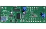
The CPG002 Customer EVM is a board containing all of the necessary components to evaluate the many
features found on the DRV8800 and DRV8801 devices. The EVM makes the evaluation process easier by
housing a microcontroller and an USB to Serial interface chip that allows for the user to control the
different DRV8800 and DRV8801 signals by means of a graphical user interface (GUI).
Figure 1. Block Diagram
1.1
Power Connectors
The CPG002 Customer EVM offers terminal blocks for the application of VM power and for motor power
outputs. VM power rail must be externally supplied. VDD for logic is internally supplied as it is derived
from the USB connection.
The user must apply VM according to datasheet recommended parameters. An USB Connection to a
computer is needed for proper control of the device.
1.2
LEDs
Three LEDs offer status information about power rails and microcontroller operating status.
1.3
Jumpers
This EVM has no jumpers that need to be configured by the user.
SLVU335A – February 2010 – Revised July 2019
Submit Documentation Feedback
Copyright © 2010–2019, Texas Instruments Incorporated
5
�1. Introduction to EVM
1.4
www.ti.com
Motor Outputs
There are two ways for connecting the motor load into the CPG002 Evaluation Module: A terminal block
and a two pin header. Each connection style offers identical connectivity to the H-Bridge output terminals.
1.5
System Requirements
· Supported OS – Windows 7 (32 Bit, 64 Bit). The window text size should be Smaller-100% (Default)
· Recommended RAM memory - 4 GB or higher
· Recommended CPU Operating Speed – 3.3 GHz or higher
2
GUI Software Installation
The following section explains the location and the procedure for installing the software properly.
2.1
GUI Software Installation
The following section explains the location of files and the procedure for installing the software correctly.
NOTE: Ensure that no USB connections are made to the EVM until the installation is completed.
The installer will also install LabVIEW RTE 2014 and FTDI Driver, along with the GUI.
6
SLVU335A – February 2010 – Revised July 2019
Submit Documentation Feedback
Copyright © 2010–2019, Texas Instruments Incorporated
�GUI Software Installation
www.ti.com
2.1.1
Installation Procedure
The following procedure helps you install the DRV8800-01EVM GUI
1. Double click on the Setup_DRV8800-01EVM.exe as shown in Figure 2.
Figure 2. Setup_DRV8800-01EVM.exe
SLVU335A – February 2010 – Revised July 2019
Submit Documentation Feedback
Copyright © 2010–2019, Texas Instruments Incorporated
7
�GUI Software Installation
www.ti.com
2. The screen shown below in Figure 3 appears, indicating installer initialization. Click the Next button.
Figure 3. Installation Initialization
8
SLVU335A – February 2010 – Revised July 2019
Submit Documentation Feedback
Copyright © 2010–2019, Texas Instruments Incorporated
�GUI Software Installation
www.ti.com
3. In the newly open installation pop-up window, click Next. The license agreement will be displayed.
Please, read through it carefully and enable the "I Accept the Agreement" radio button and press Next.
Figure 4. License Agreement
SLVU335A – February 2010 – Revised July 2019
Submit Documentation Feedback
Copyright © 2010–2019, Texas Instruments Incorporated
9
�GUI Software Installation
www.ti.com
4. A screen as shown below in Figure 5 appears, displaying the license agreement of National
Instruments. Please read through the agreement carefully and enable the “I Accept the License
Agreement” radio button and press the Next button.
Figure 5. NI License Agreement
10
SLVU335A – February 2010 – Revised July 2019
Submit Documentation Feedback
Copyright © 2010–2019, Texas Instruments Incorporated
�GUI Software Installation
www.ti.com
5. Set the default directory for the GUI Installation and click Next.
Figure 6. Installation Directory Screen
NOTE: It is highly recommended to keep the default values as provided in the installer.
SLVU335A – February 2010 – Revised July 2019
Submit Documentation Feedback
Copyright © 2010–2019, Texas Instruments Incorporated
11
�GUI Software Installation
www.ti.com
6. A screen as shown in Figure 7 appears. This screen is to select the components to install. Select the
Components to Install and Click Next to continue installation. The LabVIEW RTE component checks
out if the LabVIEW RTE 2014 is already installed on the PC.
Figure 7. Component Selection
12
SLVU335A – February 2010 – Revised July 2019
Submit Documentation Feedback
Copyright © 2010–2019, Texas Instruments Incorporated
�GUI Software Installation
www.ti.com
7. If LabVIEW RTE is selected as a component to install, a screen appears as shown in Figure 8.
Configure the proxy settings as required. This screen is to download the LabVIEW RTE 2014 from
ni.com, Click Next to continue the installation.
Figure 8. Configure Proxy
SLVU335A – February 2010 – Revised July 2019
Submit Documentation Feedback
Copyright © 2010–2019, Texas Instruments Incorporated
13
�GUI Software Installation
www.ti.com
8. A screen as shown in Figure 9 appears. Click Next to begin the installation.
Figure 9. Ready to Install
14
SLVU335A – February 2010 – Revised July 2019
Submit Documentation Feedback
Copyright © 2010–2019, Texas Instruments Incorporated
�GUI Software Installation
www.ti.com
9. If the LabVIEW RTE 2014 is selected as a component to install, LabVIEW RTE downloads and
performs a silent mode installation.
Figure 10. Downloading RTE
SLVU335A – February 2010 – Revised July 2019
Submit Documentation Feedback
Copyright © 2010–2019, Texas Instruments Incorporated
15
�GUI Software Installation
www.ti.com
10. Once the Download completes, LabVIEW begins with the self-extraction as shown in Figure 11.
Figure 11. LabVIEW RTE Self Extraction
16
SLVU335A – February 2010 – Revised July 2019
Submit Documentation Feedback
Copyright © 2010–2019, Texas Instruments Incorporated
�GUI Software Installation
www.ti.com
11. A screen appears as shown in Figure 12. It initializes the LabVIEW RTE Installation.
Figure 12. LabVIEW RTE Installation Initialization
SLVU335A – February 2010 – Revised July 2019
Submit Documentation Feedback
Copyright © 2010–2019, Texas Instruments Incorporated
17
�GUI Software Installation
www.ti.com
12. A display as shown below appears which indicates the progress of LabVIEW RTE installation.
Figure 13. Installation of LabVIEW RTE in Progress
18
SLVU335A – February 2010 – Revised July 2019
Submit Documentation Feedback
Copyright © 2010–2019, Texas Instruments Incorporated
�GUI Software Installation
www.ti.com
13. Once the LabVIEW RTE 2014 is installed, DRV 8313 EVM GUI component installs.
14. After DRV8800-01EVM Installation, FTDI Installation begins. A screen as shown in Figure 14 appears,
click Extract to proceed.
Figure 14. FTDI Installation Initialization
SLVU335A – February 2010 – Revised July 2019
Submit Documentation Feedback
Copyright © 2010–2019, Texas Instruments Incorporated
19
�GUI Software Installation
www.ti.com
15. A screen as shown in Figure 15 appears, click Next to proceed.
Figure 15. Driver Installation Wizard
20
SLVU335A – February 2010 – Revised July 2019
Submit Documentation Feedback
Copyright © 2010–2019, Texas Instruments Incorporated
�GUI Software Installation
www.ti.com
16. The License Agreement appears on screen as shown below.
17. Read through the License Agreement carefully and enable the “I Accept this Agreement” radio button
and Click on Next.
Figure 16. License Agreement for FTDI Driver
SLVU335A – February 2010 – Revised July 2019
Submit Documentation Feedback
Copyright © 2010–2019, Texas Instruments Incorporated
21
�GUI Software Installation
www.ti.com
18. Click Finish to complete the Driver Installation.
Figure 17. Driver Installation Completion
22
SLVU335A – February 2010 – Revised July 2019
Submit Documentation Feedback
Copyright © 2010–2019, Texas Instruments Incorporated
�GUI Software Installation
www.ti.com
19. The Figure 18 screen appears denoting the completion of DRV8800-01EVM GUI Installation. Click
Finish.
Figure 18. Installation Complete
SLVU335A – February 2010 – Revised July 2019
Submit Documentation Feedback
Copyright © 2010–2019, Texas Instruments Incorporated
23
�GUI Software Installation
www.ti.com
20. A Readme window as shown below appears displaying the link for LV 2014 RTE.
Figure 19. Readme Window
WARNING
The DRV8800-01EVM GUI requires the LabVIEW Run-Time Engine
2014 to be installed before the GUI executes. Please note the
application is not compatible with other versions of LabVIEW
Runtime Engine.
You can download National Instruments LabVIEW Run-Time Engine 2014
from the below link:
LabVIEW Run-Time Engine 2014
NOTE: DRV8800-01EVM GGUI executable has been built in LabVIEW 2014 (32-bit) version, and it
expects the LabVIEW Run-Time Engine version to be LabVIEW Run-Time Engine (32-bit
version).
24
SLVU335A – February 2010 – Revised July 2019
Submit Documentation Feedback
Copyright © 2010–2019, Texas Instruments Incorporated
�DRV8800-01 EVM GUI Overview
www.ti.com
3
DRV8800-01 EVM GUI Overview
The DRV8800-01EVM Windows application is the software counterpart for the CPG002 EVM. It is in
charge of connecting to the EVM via an USB connection which in turn selects the proper logic state for the
DRV8800-01EVM control signals.
The Graphical User Interface (GUI) has been designed to allow for all of the DRV8800-01EVM device’s
functionality to be tested without having to intervene with the hardware. Figure 20 shows the DRV8800-01
EVM High-Level Page. It contains menu items to configure and enable/disable the serial port and frames
with GPIO control for the DRV8800-01EVM Control Signals as well as the ability to PWM the ENABLE
and the PHASE inputs.
Figure 20. GUI Overview
SLVU335A – February 2010 – Revised July 2019
Submit Documentation Feedback
Copyright © 2010–2019, Texas Instruments Incorporated
25
�DRV8800-01 EVM GUI Overview
3.1
www.ti.com
Pages in the GUI
The GUI has one Page (High-Level Page). It contains frames with GPIO control for the DRV8800-01
control signals, motor control Frame, and PWM Frame.
3.1.1
High-Level Page
3.1.1.1
DRV8800-01 GPIO Control Signals
Once the application is communicating with the interface board, the control signals can be actuated by
checking or unchecking check boxes on the Signals frame. Green in the Pin control translates to the High
level on the respective control signal and Red in the Pin control translates to the Low level on the
respective control signal.
Figure 21. Pin Information/Control Widget
Clicking on the ENABLE and PHASE Boolean set the PWM duty cycle to 0x00 (when Low) or 0xFF (when
High). Moving the slider bar configures the PWM duty cycle to a value in between.
26
SLVU335A – February 2010 – Revised July 2019
Submit Documentation Feedback
Copyright © 2010–2019, Texas Instruments Incorporated
�DRV8800-01 EVM GUI Overview
www.ti.com
Figure 22. PHASE and ENABLE Pin Widgets
Figure 23. PHASE and ENABLE Sliders
SLVU335A – February 2010 – Revised July 2019
Submit Documentation Feedback
Copyright © 2010–2019, Texas Instruments Incorporated
27
�DRV8800-01 EVM GUI Overview
3.2
3.2.1
www.ti.com
Menu Options
File
The File menu contains the options as shown in Figure 24. Each of the options is explained below.
This is to Exit the application
Figure 24. File Menu
3.2.2
View
Under view, there is an option “Schematic” which takes the user to a menu of different device Schematics
that are available for viewing.
Figure 25. View Menu
3.2.3
Debug
The Debug option can be used for the following operations
Figure 26. Debug Menu
28
SLVU335A – February 2010 – Revised July 2019
Submit Documentation Feedback
Copyright © 2010–2019, Texas Instruments Incorporated
�DRV8800-01 EVM GUI Overview
www.ti.com
3.2.3.1
Demo
By selecting the Demo in the submenu, the GUI will run in simulation mode, and by unselecting it, the GUI
will run in connected mode.
3.2.3.2
Debug Log
The Debug log option will enable to log all the activities of the user. If that is not selected, only the highlevel operations will be logged.
3.2.3.3
Log to File
The log to file submenu is used to log the GUI activities to a log file that is specified.
3.2.4
Help
Clicking the About in the Help Menu.
Figure 27. Help Menu
3.2.4.1
About
The About Page provides the details like the Name of the GUI, GUI version, Supported OS and Copyright
Information.
SLVU335A – February 2010 – Revised July 2019
Submit Documentation Feedback
Copyright © 2010–2019, Texas Instruments Incorporated
29
�DRV8800-01 EVM GUI Overview
www.ti.com
Figure 28. About Page
30
SLVU335A – February 2010 – Revised July 2019
Submit Documentation Feedback
Copyright © 2010–2019, Texas Instruments Incorporated
�IMPORTANT NOTICE AND DISCLAIMER
TI PROVIDES TECHNICAL AND RELIABILITY DATA (INCLUDING DATA SHEETS), DESIGN RESOURCES (INCLUDING REFERENCE
DESIGNS), APPLICATION OR OTHER DESIGN ADVICE, WEB TOOLS, SAFETY INFORMATION, AND OTHER RESOURCES “AS IS”
AND WITH ALL FAULTS, AND DISCLAIMS ALL WARRANTIES, EXPRESS AND IMPLIED, INCLUDING WITHOUT LIMITATION ANY
IMPLIED WARRANTIES OF MERCHANTABILITY, FITNESS FOR A PARTICULAR PURPOSE OR NON-INFRINGEMENT OF THIRD
PARTY INTELLECTUAL PROPERTY RIGHTS.
These resources are intended for skilled developers designing with TI products. You are solely responsible for (1) selecting the appropriate
TI products for your application, (2) designing, validating and testing your application, and (3) ensuring your application meets applicable
standards, and any other safety, security, regulatory or other requirements.
These resources are subject to change without notice. TI grants you permission to use these resources only for development of an
application that uses the TI products described in the resource. Other reproduction and display of these resources is prohibited. No license
is granted to any other TI intellectual property right or to any third party intellectual property right. TI disclaims responsibility for, and you
will fully indemnify TI and its representatives against, any claims, damages, costs, losses, and liabilities arising out of your use of these
resources.
TI’s products are provided subject to TI’s Terms of Sale or other applicable terms available either on ti.com or provided in conjunction with
such TI products. TI’s provision of these resources does not expand or otherwise alter TI’s applicable warranties or warranty disclaimers for
TI products.
TI objects to and rejects any additional or different terms you may have proposed. IMPORTANT NOTICE
Mailing Address: Texas Instruments, Post Office Box 655303, Dallas, Texas 75265
Copyright © 2022, Texas Instruments Incorporated
�