User's Guide
SLVUAI1B – July 2015 – Revised September 2019
DRV8880 Evaluation Module (EVM) Hardware and GUI
User's Guide
This document is provided with the DRV8880 customer EVM as a supplement to the DRV8880
(SLVSD18) data sheet. This user's guide details the hardware implementation of the EVM.
Contents
1
Introduction ................................................................................................................... 2
2
Connectors ................................................................................................................... 3
3
Test Points .................................................................................................................... 4
4
Jumpers ....................................................................................................................... 4
5
Motor Outputs ............................................................................................................... 4
6
Operation of the EVM ....................................................................................................... 5
7
Motion Control Frame (Includes Start/Stop Steps and Move Steps) ................................................. 8
Appendix A
....................................................................................................................... 11
List of Figures
................................................
1
Top View of Typical Board Configuration (EVM Provided may Vary)
2
Connections .................................................................................................................. 3
3
GUI at Startup ................................................................................................................ 5
4
Wake and Enable Toggle Buttons ......................................................................................... 6
5
Motor Controls Enabled ..................................................................................................... 7
6
Motor Motion Profile ......................................................................................................... 8
7
Acceleration Profile .......................................................................................................... 9
8
Stop Conditions............................................................................................................. 10
9
User Account Control Window............................................................................................ 11
10
EVM Setup Wizard ......................................................................................................... 12
11
License Agreement
12
Installation Folders ......................................................................................................... 12
13
Possible Upgrade Question ............................................................................................... 13
14
Ready to Install ............................................................................................................. 14
15
Completed ................................................................................................................... 14
........................................................................................................
2
12
List of Tables
1
Connections to DRV8880 Using External Microcontroller .............................................................. 4
Trademarks
Microsoft, Windows are registered trademarks of Microsoft Corporation.
All other trademarks are the property of their respective owners.
SLVUAI1B – July 2015 – Revised September 2019
Submit Documentation Feedback
DRV8880 Evaluation Module (EVM) Hardware and GUI User's Guide
Copyright © 2015–2019, Texas Instruments Incorporated
1
�Introduction
1
www.ti.com
Introduction
The DRV8880 customer EVM is a platform revolving around the DRV8880, a medium voltage dual Hbridge driver and highly-configurable power stage. This device has been optimized to drive a single bipolar
stepper with up to 16 degrees of internally generated microstepping.
The EVM houses an MSP430 microcontroller and an USB interface chip. The USB chip allows for serial
communications from a PC where a Microsoft® Windows® application is used to schedule serial
commands. These commands can be used to control each of the device’s signals and drive the stepper
motor by issuing the step commands at the desired rate.
The microcontroller firmware operates using internal index mode.
This user's guide details the operation of the EVM, as well as the hardware configurability of the EVM.
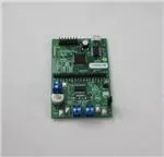
Power Connector
MicroUSB
Header
Microcontroller Section
Motor Connections
DRV8880
Figure 1. Top View of Typical Board Configuration (EVM Provided may Vary)
2
DRV8880 Evaluation Module (EVM) Hardware and GUI User's Guide
SLVUAI1B – July 2015 – Revised September 2019
Submit Documentation Feedback
Copyright © 2015–2019, Texas Instruments Incorporated
�Connectors
www.ti.com
2
Connectors
The DRV8880EVM offers access to VM (motor voltage) power rail through a terminal block (J1). A set of
test clips in parallel with the terminal block allows for the monitoring of the input power rail.
User must apply VM according to data sheet recommended parameters.
NOTE: VDD for the microcontroller is derived from the micro USB connector.
Connect
USB here
Connect Motor here
Connect Power and
Ground here
Figure 2. Connections
SLVUAI1B – July 2015 – Revised September 2019
Submit Documentation Feedback
DRV8880 Evaluation Module (EVM) Hardware and GUI User's Guide
Copyright © 2015–2019, Texas Instruments Incorporated
3
�Test Points
3
www.ti.com
Test Points
A 0.100-inch pitch header connector (J6) provides access to every device signal in the event a different
microcontroller is to be employed. To disconnect the internal MSP430 microcontroller, remove resistor
packs R3 and R4. Table 1 describes the connections available on the J6 header. Each header pin is
labeled on the EVM and matches the pin of the DRV8880.
Table 1. Connections to DRV8880 Using External
Microcontroller
4
HEADER LABEL
DESCRIPTION
V3P3R or V3P3_GPIO
3.3 V after 33-Ω resistor
nFAULT
Fault output
nSLEEP
Sleep mode input
PIN14
VREF, comparator reference input
PIN22
DIR, direction input
PIN21
ENABLE, stepper motor enable
PIN23
STEP, step input
PIN25
USM0, step mode
PIN24
USM1, step mode
TOFF
Off-time selection
PIN13
AutoTune select
8xV3P3
Internal supply voltage to set DAC voltage
TRQ0
Torque (current level)
TRQ1
Torque (current level)
PIN20
DECAY0, decay mode
PIN19
DECAY1, decay mode
GND
Ground
GND
Ground
Jumpers
J3 is used to select latched or retry mode. To select retry mode, place a shunt on J3. If latched mode is
desired, place the shunt across J7.
NOTE: J5 is not used for the DRV8880. It should not be populated on the PCB.
5
Motor Outputs
Two motor connectors are provided. Connectors J2 and J4 are available as shown in Figure 1.
4
DRV8880 Evaluation Module (EVM) Hardware and GUI User's Guide
SLVUAI1B – July 2015 – Revised September 2019
Submit Documentation Feedback
Copyright © 2015–2019, Texas Instruments Incorporated
�Operation of the EVM
www.ti.com
6
Operation of the EVM
1.
2.
3.
4.
Install the drivers and GUI. Refer to Appendix A for instructions.
Connect the wires of the stepper motor to terminals AOUT1, AOUT2, BOUT1, and BOUT2.
Connect the VM power supply, but do not apply power at this step.
Connect the USB cable between the PC and the EVM. After the USB is connected to the EVM, the
Status LED will begin to blink.
5. Open the GUI by double clicking the icon. It may take up to 30 seconds to establish connection. If
connection is not established, select the COM port under the Options menu. The BaudRate is 9600.
• After the USB connection is established, the Status LED will begin to blink.
6. Apply desired voltage (6.5 to 45 V) to the VM and GND connections.
7. Configure the current settings, step mode, torque, and PWM off time as desired as shown below. Note
that the Decay Mode selection is only available when AutoTune is disabled.
a. The current is calculated using the VREF slider, the Sense resistor value, the Torque setting, and
the Step mode setting using Equation 1.
VREF
I FS
u TORQUE u StepModifier
6.6 u RISENSE
where StepModifier is 0.71 for full step and 1.0 for others STEP MODE settings
(1)
b. The 12-bit DAC channel 0 is connected to the DRV8880 analog input VREF. Changing the DAC
digital value from 0 to 4095 in steps of 4, changes the analog voltage at the VREF pin from 0 V to
VINT V. See Equation 2.
VINT
VREF
u VREF _ slider u 4
4095
where
•
•
VINT is the output of the DRV8880 V3P3 pin
VREF_slider is the slider value from 0 to 1023.
(2)
Figure 3. GUI at Startup
SLVUAI1B – July 2015 – Revised September 2019
Submit Documentation Feedback
DRV8880 Evaluation Module (EVM) Hardware and GUI User's Guide
Copyright © 2015–2019, Texas Instruments Incorporated
5
�Operation of the EVM
www.ti.com
8. Wake and Enable the device for operation.
a. After setting up the controls signals for the DRV8880, enabling the DRV8880 requires selecting
both the WAKE and ENABLE toggle buttons. When toggled, WAKE or ENABLE switches between
red to green.
b. The WAKE toggle button, which controls the nSLEEP pin, is used to wake the DRV8880. The
ENABLE toggle button, which controls the nENBL pin, is used to enable the DRV8880 outputs.
c. A message which states that “Both WAKE and ENABLE must be green to enable the motor control
buttons” will be visible until both the WAKE and ENABLE toggle buttons are activated. After these
two toggle buttons have been activated, the message disappears and the Start/Stop and Move
Steps toggle buttons will be available.
d. If the WAKE or ENABLE toggle buttons are selected during motor operation, the motor is
immediately stopped and the STEP control signal from the microcontroller is reset.
Figure 4. Wake and Enable Toggle Buttons
6
DRV8880 Evaluation Module (EVM) Hardware and GUI User's Guide
SLVUAI1B – July 2015 – Revised September 2019
Submit Documentation Feedback
Copyright © 2015–2019, Texas Instruments Incorporated
�Operation of the EVM
www.ti.com
9. The DRV8880 EVM is now awake and can be commanded to turn the motor. The user can command
the EVM by either selecting “Start/Stop Steps”, “Move # of Steps”, or “Reciprocate".
The “Start/Stop Steps” toggle button is used to run the motor indefinitely. The motor will accelerate to
the target speed and run until the “Start/Stop Steps” toggle button is selected. When the “Start/Stop
Steps” toggle button is selected, the red button will change to green, and the “Move Steps” and
“Reciprocate” toggle buttons will be disabled.
The “Move Steps” toggle button is used to allow movement of an exact number of steps. When the
“Move Steps” toggle button is selected, “Move Steps” will turn green, and the “Start/Stop Steps” and
“Reciprocate” toggle buttons are disabled until the number of steps have completed.
The “Reciprocate” toggle button is a special case of the “Move Steps”. When selected, the motor will
advance the specified number of steps in the direction initially set by the control inputs. After a short
pause, the motor will then advance the same number of steps in the opposite direction. This sequence
is repeated until the “Reciprocate” toggle button is selected.
When the “Reciprocate” toggle button is selected, “Reciprocate” will turn green, and the “Start/Stop
Steps” and “Move # of Steps” buttons are disabled until the “Reciprocate” toggle button is set to red,
and the number of steps have completed.
Figure 5. Motor Controls Enabled
As an extra precaution, the motor can be stopped by selecting either the WAKE or ENABLE toggle
buttons. When either is selected, the STEP commands are stopped, and the motor control buttons are
disabled. To re-enable motor control, set the WAKE and ENABLE toggle buttons to green.
SLVUAI1B – July 2015 – Revised September 2019
Submit Documentation Feedback
DRV8880 Evaluation Module (EVM) Hardware and GUI User's Guide
Copyright © 2015–2019, Texas Instruments Incorporated
7
�Motion Control Frame (Includes Start/Stop Steps and Move Steps)
7
www.ti.com
Motion Control Frame (Includes Start/Stop Steps and Move Steps)
The GUI has an area which offers access to a series of useful stepper control algorithms. This area allows
for determining the best current settings during running at various speeds and when holding torque is
applied.
Both WAKE and ENABLE must be green to enable the motor control buttons.
Figure 6. Motor Motion Profile
Motor motion can only happen by using an acceleration profile which will be detailed later on. A detailed
explanation of each stepper control section follows.
This frame allows the configuration and running of the stepper with the direction as specified by the DIR
checkbox, with the current decay mode as specified under the Decay Mode checkbox and the
microstepping resolution as specified under the Step Mode dropdown box.
The Motion Control frame gathers user information regarding stepping rate or motor speed. An
acceleration profile is employed to start at a programmable speed and increase stepping rate until
reaching the programmable desired speed.
An internal 8-MHz timer is used to measure time and generate the steps on a timely manner. The GUI will
send the information to the microcontroller as PPS, and the microcontroller will transform it into the
respective clock cycles needed for the timer to generate accurate STEP pulse timing.
8
DRV8880 Evaluation Module (EVM) Hardware and GUI User's Guide
SLVUAI1B – July 2015 – Revised September 2019
Submit Documentation Feedback
Copyright © 2015–2019, Texas Instruments Incorporated
�Motion Control Frame (Includes Start/Stop Steps and Move Steps)
www.ti.com
7.1
Start/Stop Steps
The acceleration profile is coded inside of the microcontroller to accept both the starting speed PPS and
target speed PPS as a clock cycle number. When the start steps command is issued (Starts/Steps button
is selected), the PWM timer will generate steps at a rate specified by the start speed PPS parameter.
When accelerating or decelerating, PPS is adjusted every 32 ms based on the integer value of PPSPS /
32 ms. If a non-zero value of PPSPS is entered, a minimum value of 1 is used. The step rate is increased
by the calculated value until the target speed is reached.
The same start steps command computes how frequent automatic speed updates are issued. A second
timer is used to change the speed according to the programmed acceleration rate profile.
When the target speed PPS is reached, the acceleration profile ends and the motor stays running until the
stop stepper command is issued (Start/Stop Steps button is selected again). When the stepper is
commanded to stop, the controller does exactly as it did while accelerating, but in reverse to decelerate
until the stop speed PPS is reached, in which case the motor fully stops.
A second motor actuation is provided by the “Move # of Steps” and “Reciprocate” commands in which a
programmed number of steps are issued and then the motor stopped. The acceleration and deceleration
profiles work similarly as before, except when the deceleration starts and when the motor actually stops
are a function of the “Steps to Stop” and deceleration rate parameters.
Figure 7 shows the acceleration profile and the role each parameter plays during speed computation.
Both WAKE and ENABLE must be green to enable the motor control buttons.
Figure 7. Acceleration Profile
SLVUAI1B – July 2015 – Revised September 2019
Submit Documentation Feedback
DRV8880 Evaluation Module (EVM) Hardware and GUI User's Guide
Copyright © 2015–2019, Texas Instruments Incorporated
9
�Motion Control Frame (Includes Start/Stop Steps and Move Steps)
7.2
www.ti.com
Move Steps
If the user desires to move the stepper a certain number of steps, accomplish this by using the move
steps function. Parameters from the other frames are reused as explained previously. Two new
parameters have been added to properly control the limited number of steps actuation.
Number of Steps— Number of steps the controller will issue.
Steps to Stop— The controller is continuously monitoring the step being issued and when the current
step is equal to the steps to stop parameter, a deceleration profile is issued. If “Steps to Stop” is
larger than the number of steps, then the motor stops abruptly and without undergoing a
deceleration profile.
When a deceleration profile is issued, the controller decreases the speed until reaching the stop speed
value. If the number of steps parameter is met before the deceleration profile is complete, then the motor
stops at the current speed. If the stop speed is met before all the number of steps is issued, then the
motor rotates at the stop speed value until all the steps are executed.
Ideally, the system should be tuned to resemble the case in which the controller executes all the
commanded steps at a speed as close as possible to the stop speed. In the event this is not possible, due
to the particular parameters being chosen, stopping the motor at a speed very close to the stop speed is
often sufficient to ensure good motion quality and application performance.
Figure 8 shows the three conditions possible when stopping and what action results.
1. Motor reaches stop speed at the stop speed.
2. Motor reaches stop speed before the stop speed is reached.
3. Motor runs out of steps before reaching stop speed.
Figure 8. Stop Conditions
7.3
EVM Documentation
The EVM schematics, layout, and bill of materials (BOM) are provided in the hardware file (SLVC623).
The GUI, USB drivers, and MSP430F2617 source code are provided in the software file (SLVC627).
10
DRV8880 Evaluation Module (EVM) Hardware and GUI User's Guide
SLVUAI1B – July 2015 – Revised September 2019
Submit Documentation Feedback
Copyright © 2015–2019, Texas Instruments Incorporated
�Appendix A
SLVUAI1B – July 2015 – Revised September 2019
A.1
Driver and GUI Installation Instructions
1. Installing the FTDI Driver:
In many cases, connecting the EVM to the computer automatically installs the FTDI driver.
If necessary, download the driver from the software file. Unzip the software file and install the USB
driver:
• If using Windows XP, run \USB driver\CDM v2.10.00 WHQL Certified.exe.
• If using Windows 7, go to folder \USB driver\, right-click CDM v2.10.00 WHQL Certified.exe, select
Properties, go to the Compatibility tab, check “Run this program in compatibility mode for”, select
“Windows XP (Service Pack 2)”, and click OK. Then, run CDM v2.10.00 WHQL Certified.exe, and
click Yes on the popup window.
2. Installing the GUI:
Locate the file DRV8880EVM_installer.zip in the Application folder. Unzip the file to any location, then
double click the file GUIComposerApp-v1.setup-win_2.0.3.exe in the unzipped folder.
The installer will begin. The following popup windows will appear.
Select Yes to continue (see Figure 9).
Figure 9. User Account Control Window
SLVUAI1B – July 2015 – Revised September 2019
Submit Documentation Feedback
Copyright © 2015–2019, Texas Instruments Incorporated
11
�Driver and GUI Installation Instructions
www.ti.com
Select Next to continue (see Figure 10).
Figure 10. EVM Setup Wizard
Select I accept the agreement and Next to continue (see Figure 11).
Figure 11. License Agreement
Select Next to continue (see Figure 12).
Figure 12. Installation Folders
12
SLVUAI1B – July 2015 – Revised September 2019
Submit Documentation Feedback
Copyright © 2015–2019, Texas Instruments Incorporated
�Driver and GUI Installation Instructions
www.ti.com
At this point, a few options may appear. If the GUI Composer Runtime v.2.0.6 has not been previously
installed, select Install from File radio button and download the runtime from the following link, GC
Runtime v2.0.6. Click the Search button to the right of the text box next to Install from File and select
the downloaded runtime v.2.0.6 file. Click Next to continue.
If the GUI has been previously installed a message similar to Figure 13 may appear. If so, select Yes,
then Next to continue (see Figure 13).
Figure 13. Possible Upgrade Question
SLVUAI1B – July 2015 – Revised September 2019
Submit Documentation Feedback
Copyright © 2015–2019, Texas Instruments Incorporated
13
�Driver and GUI Installation Instructions
www.ti.com
Select Next to continue (see Figure 14).
Figure 14. Ready to Install
Click the desired results, then select Finish to complete (see Figure 15).
Figure 15. Completed
14
SLVUAI1B – July 2015 – Revised September 2019
Submit Documentation Feedback
Copyright © 2015–2019, Texas Instruments Incorporated
�IMPORTANT NOTICE AND DISCLAIMER
TI PROVIDES TECHNICAL AND RELIABILITY DATA (INCLUDING DATASHEETS), DESIGN RESOURCES (INCLUDING REFERENCE
DESIGNS), APPLICATION OR OTHER DESIGN ADVICE, WEB TOOLS, SAFETY INFORMATION, AND OTHER RESOURCES “AS IS”
AND WITH ALL FAULTS, AND DISCLAIMS ALL WARRANTIES, EXPRESS AND IMPLIED, INCLUDING WITHOUT LIMITATION ANY
IMPLIED WARRANTIES OF MERCHANTABILITY, FITNESS FOR A PARTICULAR PURPOSE OR NON-INFRINGEMENT OF THIRD
PARTY INTELLECTUAL PROPERTY RIGHTS.
These resources are intended for skilled developers designing with TI products. You are solely responsible for (1) selecting the appropriate
TI products for your application, (2) designing, validating and testing your application, and (3) ensuring your application meets applicable
standards, and any other safety, security, or other requirements. These resources are subject to change without notice. TI grants you
permission to use these resources only for development of an application that uses the TI products described in the resource. Other
reproduction and display of these resources is prohibited. No license is granted to any other TI intellectual property right or to any third
party intellectual property right. TI disclaims responsibility for, and you will fully indemnify TI and its representatives against, any claims,
damages, costs, losses, and liabilities arising out of your use of these resources.
TI’s products are provided subject to TI’s Terms of Sale (www.ti.com/legal/termsofsale.html) or other applicable terms available either on
ti.com or provided in conjunction with such TI products. TI’s provision of these resources does not expand or otherwise alter TI’s applicable
warranties or warranty disclaimers for TI products.
Mailing Address: Texas Instruments, Post Office Box 655303, Dallas, Texas 75265
Copyright © 2019, Texas Instruments Incorporated
�