DS25CP102Q
www.ti.com
SNLS293E – MAY 2008 – REVISED APRIL 2013
DS25CP102Q Automotive 3.125 Gbps 2X2 LVDS Crosspoint Switch with Transmit PreEmphasis and Receive Equalization
Check for Samples: DS25CP102Q
FEATURES
DESCRIPTION
•
•
The DS25CP102Q is a 3.125 Gbps 2x2 LVDS
crosspoint switch optimized for high-speed signal
routing and switching over lossy FR-4 printed circuit
board backplanes and balanced cables. Fully
differential signal paths ensure exceptional signal
integrity and noise immunity. The non-blocking
architecture allows connections of any input to any
output or outputs.
1
2
•
•
•
•
•
•
AECQ-100 Grade 3
DC - 3.125 Gbps Low Jitter, Low Skew, Low
Power Operation
Pin Configurable, Fully Differential, NonBlocking Architecture
Pin Selectable Transmit Pre-Emphasis and
Receive Equalization Eliminate Data
Dependant Jitter
Wide Input Common Mode Voltage Range
Allows DC-coupled Interface to CML and
LVPECL Drivers
On-Chip 100Ω Input and Output Termination
Minimizes Insertion and Return Losses,
Reduces Component Count and Minimizes
Board Space
8 kV ESD on LVDS I/O pins Protects Adjoining
components
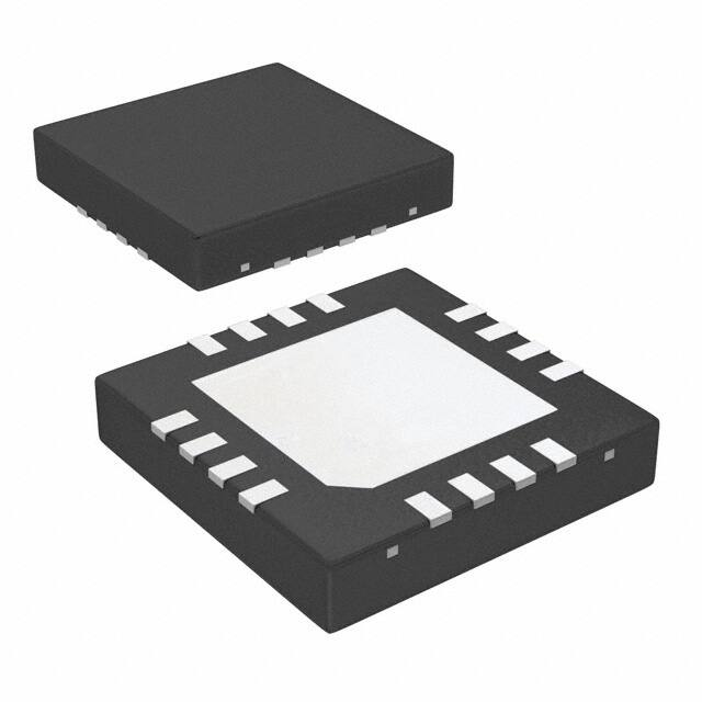
Small 4 mm x 4 mm WQFN-16 Space Saving
Package
The DS25CP102Q features two levels (Off and On)
of transmit pre-emphasis (PE) and two levels (Off and
On) of receive equalization (EQ).
Wide input common mode range allows the switch to
accept signals with LVDS, CML and LVPECL levels;
the output levels are LVDS. A very small package
footprint requires a minimal space on the board while
the flow-through pinout allows easy board layout.
Each differential input and output is internally
terminated with a 100Ω resistor to lower device
insertion and return losses, reduce component count
and further minimize board space.
APPLICATIONS
•
•
•
•
Automotive Display Applications
Clock and Data Buffering and Muxing
OC-48 / STM-16
SD/HD/3GHD SDI Routers
1
2
Please be aware that an important notice concerning availability, standard warranty, and use in critical applications of
Texas Instruments semiconductor products and disclaimers thereto appears at the end of this data sheet.
All trademarks are the property of their respective owners.
PRODUCTION DATA information is current as of publication date.
Products conform to specifications per the terms of the Texas
Instruments standard warranty. Production processing does not
necessarily include testing of all parameters.
Copyright © 2008–2013, Texas Instruments Incorporated
�DS25CP102Q
SNLS293E – MAY 2008 – REVISED APRIL 2013
www.ti.com
Typical Application
DS25CP102Q
2x2 CROSSPOINT
RED
RED
Navigation
Computer
24 TO 1
1 TO 24
GREEN
MONITOR
1
GREEN
BLUE
BLUE
SEL0
DS90UR241Q
DS90UR124Q
SEL1
RED
RED
Entertainment
System
1 TO 24
GREEN
MONITOR
2
GREEN
24 TO 1
BLUE
BLUE
DS90UR241Q
EQ
PE
DS90UR124Q
SIGNAL CONDITIONING
PE
EN0
EN1
14
13
IN0-
2
DAP
IN1+
3
(GND)
IN1-
4
PE
8
EQ
OUT1-
1
SEL1
PE
OUT1+
IN0+
7
EN1
EQ
IN1-
OUT0-
SEL0
2X2
IN1+
OUT0+
6
PE
EQ
EQ
IN0-
15
EN0
IN0+
VCC
SEL0
5
SEL1
16
Connection Diagram
GND
Block Diagram
12
OUT0+
11
OUT0-
10
OUT1+
9
OUT1-
PIN DESCRIPTIONS
Pin Name
Pin
Number
I/O, Type
Pin Description
IN0+, IN0- ,
IN1+, IN1-
1, 2,
3, 4
I, LVDS
Inverting and non-inverting high speed LVDS input pins.
OUT0+, OUT0-,
OUT1+, OUT1-
12, 11,
10, 9
O, LVDS
Inverting and non-inverting high speed LVDS output pins.
SEL0, SEL1
7, 8
I, LVCMOS
Switch configuration pins. There is a 20k pulldown resistor on this pin.
EN0, EN1
14, 13
I, LVCMOS
Output enable pins. There is a 20k pulldown resistor on this pin.
PE
15
I, LVCMOS
Transmit Pre-Emphasis select pin. There is a 20k pulldown resistor on this pin.
EQ
6
I, LVCMOS
Receive Equalization select pin. There is a 20k pulldown resistor on this pin.
VCC
16
Power
Power supply pin.
GND
5, DAP
Power
Ground pin and Device Attach Pad (DAP) ground.
2
Submit Documentation Feedback
Copyright © 2008–2013, Texas Instruments Incorporated
Product Folder Links: DS25CP102Q
�DS25CP102Q
www.ti.com
SNLS293E – MAY 2008 – REVISED APRIL 2013
These devices have limited built-in ESD protection. The leads should be shorted together or the device placed in conductive foam
during storage or handling to prevent electrostatic damage to the MOS gates.
Absolute Maximum Ratings
(1) (2)
−0.3V to +4V
Supply Voltage
−0.3V to (VCC + 0.3V)
LVCMOS Input Voltage
−0.3V to +4V
LVDS Input Voltage
Differential Input Voltage |VID|
1.0V
−0.3V to (VCC + 0.3V)
LVDS Output Voltage
LVDS Differential Output Voltage
0V to 1.0V
LVDS Output Short Circuit Current Duration
5 ms
Junction Temperature
+105°C
−65°C to +150°C
Storage Temperature Range
Lead Temperature Range
Soldering (4 sec.)
+260°C
Maximum Package Power Dissipation at 25°C
RGH0016A Package
1.91W
Derate RGH0016A Package
23.9 mW/°C above +25°C
Package Thermal Resistance
θJA
+41.8°C/W
θJC
+6.9°C/W
ESD Susceptibility
HBM
MM
(3)
CDM
(1)
(2)
(3)
(4)
(5)
≥8 kV
(4)
≥250V
(5)
≥1250V
“Absolute Maximum Ratings” indicate limits beyond which damage to the device may occur, including inoperability and degradation of
device reliability and/or performance. Functional operation of the device and/or non-degradation at the Absolute Maximum Ratings or
other conditions beyond those indicated in the Recommended Operating Conditions is not implied. The Recommended Operating
Conditions indicate conditions at which the device is functional and the device should not be operated beyond such conditions.
If Military/Aerospace specified devices are required, please contact the TI Sales Office/Distributors for availability and specifications.
Human Body Model, applicable std. JESD22-A114C
Machine Model, applicable std. JESD22-A115-A
Field Induced Charge Device Model, applicable std. JESD22-C101-C
Recommended Operating Conditions
Supply Voltage (VCC)
Receiver Differential Input Voltage (VID)
Operating Free Air Temperature (TA)
Min
Typ
Max
Units
3.0
3.3
3.6
V
1
V
+85
°C
0
−40
+25
DC Electrical Characteristics (1) (2) (3)
Over recommended operating supply and temperature ranges unless otherwise specified.
Symbol
Parameter
Conditions
Min
Typ
Max
Units
LVCMOS DC SPECIFICATIONS
VIH
High Level Input Voltage
2.0
VCC
V
VIL
Low Level Input Voltage
GND
0.8
V
(1)
(2)
(3)
The Electrical Characteristics tables list ensured specifications under the listed Recommended Operating Conditions except as
otherwise modified or specified by the Electrical Characteristics Conditions and/or Notes. Typical specifications are estimations only and
are not ensured.
Current into device pins is defined as positive. Current out of device pins is defined as negative. All voltages are referenced to ground
except VOD and ΔVOD.
Typical values represent most likely parametric norms for VCC = +3.3V and TA = +25°C, and at the Recommended Operation Conditions
at the time of product characterization and are not ensured.
Submit Documentation Feedback
Copyright © 2008–2013, Texas Instruments Incorporated
Product Folder Links: DS25CP102Q
3
�DS25CP102Q
SNLS293E – MAY 2008 – REVISED APRIL 2013
www.ti.com
DC Electrical Characteristics(1)(2)(3) (continued)
Over recommended operating supply and temperature ranges unless otherwise specified.
Symbol
Parameter
Conditions
IIH
High Level Input Current
VIN = 3.6V
VCC = 3.6V
IIL
Low Level Input Current
VIN = GND
VCC = 3.6V
VCL
Input Clamp Voltage
ICL = −18 mA, VCC = 0V
Min
Typ
Max
Units
40
175
250
μA
0
±10
μA
−0.9
−1.5
V
1
V
+100
mV
LVDS INPUT DC SPECIFICATIONS
VID
Input Differential Voltage
0
VTH
Differential Input High Threshold
VTL
Differential Input Low Threshold
VCMR
Common Mode Voltage Range
VID = 100 mV
IIN
Input Current
VIN = +3.6V or 0V
VCC = 3.6V or 0V
±1
CIN
Input Capacitance
Any LVDS Input Pin to GND
1.7
pF
RIN
Input Termination Resistor
Between IN+ and IN-
100
Ω
VCM = +0.05V or VCC-0.05V
0
−100
0
0.05
mV
VCC 0.05
V
±10
μA
LVDS OUTPUT DC SPECIFICATIONS
VOD
Differential Output Voltage
ΔVOD
Change in Magnitude of VOD for Complimentary
Output States
250
VOS
Offset Voltage
ΔVOS
Change in Magnitude of VOS for Complimentary
Output States
IOS
Output Short Circuit Current
RL = 100Ω
-35
1.05
(4)
350
RL = 100Ω
1.2
-35
450
mV
35
mV
1.375
V
35
mV
OUT to GND
-35
-55
mA
OUT to VCC
7
55
mA
COUT
Output Capacitance
Any LVDS Output Pin to GND
1.2
pF
ROUT
Output Termination Resistor
Between OUT+ and OUT-
100
Ω
SUPPLY CURRENT
ICC
Supply Current
PE = OFF, EQ = OFF
77
90
mA
ICCZ
Supply Current with Outputs Disabled
EN0 = EN1 = 0
23
29
mA
Typ
Max
Units
365
500
ps
345
500
ps
(4)
Output short circuit current (IOS) is specified as magnitude only, minus sign indicates direction only.
AC Electrical Characteristics (1)
Over recommended operating supply and temperature ranges unless otherwise specified.
Symbol
Parameter
Conditions
(2) (3)
Min
LVDS OUTPUT AC SPECIFICATIONS
tPLHD
Differential Propagation Delay Low to
High
tPHLD
Differential Propagation Delay High to
Low
tSKD1
Pulse Skew |tPLHD − tPHLD|
(4)
20
55
ps
tSKD2
Channel to Channel Skew
(5)
12
25
ps
(1)
(2)
(3)
(4)
(5)
4
RL = 100Ω
Specification is ensured by characterization and is not tested in production.
The Electrical Characteristics tables list ensured specifications under the listed Recommended Operating Conditions except as
otherwise modified or specified by the Electrical Characteristics Conditions and/or Notes. Typical specifications are estimations only and
are not ensured.
Typical values represent most likely parametric norms for VCC = +3.3V and TA = +25°C, and at the Recommended Operation Conditions
at the time of product characterization and are not ensured.
tSKD1, |tPLHD − tPHLD|, Pulse Skew, is the magnitude difference in differential propagation delay time between the positive going edge and
the negative going edge of the same channel.
tSKD2, Channel to Channel Skew, is the difference in propagation delay (tPLHD or tPHLD) among all output channels in Broadcast mode
(any one input to all outputs).
Submit Documentation Feedback
Copyright © 2008–2013, Texas Instruments Incorporated
Product Folder Links: DS25CP102Q
�DS25CP102Q
www.ti.com
SNLS293E – MAY 2008 – REVISED APRIL 2013
AC Electrical Characteristics(1) (continued)
Over recommended operating supply and temperature ranges unless otherwise specified. (2) (3)
Symbol
Parameter
Conditions
(6)
tSKD3
Part to Part Skew ,
tLHT
Rise Time
tHLT
Fall Time
tON
Output Enable Time
ENn = LH to output active
tOFF
Output Disable Time
ENn = HL to output inactive
tSEL
Select Time
SELn LH or HL to output
RL = 100Ω
Min
Typ
Max
Units
50
150
ps
65
120
ps
65
120
ps
7
20
μs
5
12
ns
3.5
12
ns
1
ps
JITTER PERFORMANCE WITH EQ = Off, PE = Off (Figure 5)
tRJ1
tRJ2
tDJ1
tDJ2
tTJ1
tTJ2
Random Jitter (RMS Value)
No Test Channels
VID = 350 mV
VCM = 1.2V
Clock (RZ)
2.5 Gbps
0.5
3.125 Gbps
0.5
1
ps
Deterministic Jitter (Peak to Peak)
No Test Channels
VID = 350 mV
VCM = 1.2V
K28.5 (NRZ)
2.5 Gbps
6
22
ps
3.125 Gbps
6
22
ps
Total Jitter (Peak to Peak)
No Test Channels
VID = 350 mV
VCM = 1.2V
PRBS-23 (NRZ)
2.5 Gbps
0.03
0.08
UIP-P
3.125 Gbps
0.05
0.11
UIP-P
(7)
(8)
(9)
JITTER PERFORMANCE WITH EQ = Off, PE = On (Figure 6 and Figure 9)
tRJ1B
tRJ2B
tDJ1B
tDJ2B
tTJ1B
tTJ2B
Random Jitter (RMS Value)
Test Channel B
VID = 350 mV
VCM = 1.2V
Clock (RZ)
2.5 Gbps
0.5
1
ps
3.125 Gbps
0.5
1
ps
Deterministic Jitter (Peak to Peak)
Test Channel B
VID = 350 mV
VCM = 1.2V
K28.5 (NRZ)
2.5 Gbps
3
12
ps
3.125 Gbps
3
12
ps
Total Jitter (Peak to Peak)
Test Channel B
VID = 350 mV
VCM = 1.2V
PRBS-23 (NRZ)
2.5 Gbps
0.03
0.06
UIP-P
3.125 Gbps
0.04
0.09
UIP-P
(7)
(8)
(10)
JITTER PERFORMANCE WITH EQ = On, PE = Off (Figure 7 and Figure 9)
tRJ1D
tRJ2D
tDJ1D
tDJ2D
tTJ1D
tTJ2D
Random Jitter (RMS Value)
Test Channel D
VID = 350 mV
VCM = 1.2V
Clock (RZ)
2.5 Gbps
0.5
1
ps
3.125 Gbps
0.5
1
ps
Deterministic Jitter (Peak to Peak)
Test Channel D
VID = 350 mV
VCM = 1.2V
K28.5 (NRZ)
2.5 Gbps
16
24
ps
3.125 Gbps
12
24
ps
Total Jitter (Peak to Peak)
Test Channel D
VID = 350 mV
VCM = 1.2V
PRBS-23 (NRZ)
2.5 Gbps
0.07
0.11
UIP-P
3.125 Gbps
0.07
0.11
UIP-P
(11)
(12)
(10)
JITTER PERFORMANCE WITH EQ = On, PE = On (Figure 8 and Figure 9)
tRJ1BD
tRJ2BD
Random Jitter (RMS Value)
Input Test Channel D
Output Test Channel B
VID = 350 mV
VCM = 1.2V
Clock (RZ)
2.5 Gbps
0.5
1
ps
3.125 Gbps
0.5
1
ps
Deterministic Jitter (Peak to Peak)
Input Test Channel D
Output Test Channel B
VID = 350 mV
VCM = 1.2V
K28.5 (NRZ)
2.5 Gbps
14
31
ps
3.125 Gbps
6
21
ps
(11)
tDJ1BD
tDJ2BD
(12)
(6)
tSKD3, Part to Part Skew, is defined as the difference between the minimum and maximum differential propagation delays. This
specification applies to devices at the same VCC and within 5°C of each other within the operating temperature range.
(7) Measured on a clock edge with a histogram and an acummulation of 1500 histogram hits. Input stimulus jitter is subtracted
geometrically.
(8) Tested with a combination of the 1100000101 (K28.5+ character) and 0011111010 (K28.5- character) patterns. Input stimulus jitter is
subtracted algebraically.
(9) Measured on an eye diagram with a histogram and an acummulation of 3500 histogram hits. Input stimulus jitter is subtracted.
(10) Measured on an eye diagram with a histogram and an acummulation of 3500 histogram hits. Input stimulus jitter is subtracted.
(11) Measured on a clock edge with a histogram and an acummulation of 1500 histogram hits. Input stimulus jitter is subtracted
geometrically.
(12) Tested with a combination of the 1100000101 (K28.5+ character) and 0011111010 (K28.5- character) patterns. Input stimulus jitter is
subtracted algebraically.
Submit Documentation Feedback
Copyright © 2008–2013, Texas Instruments Incorporated
Product Folder Links: DS25CP102Q
5
�DS25CP102Q
SNLS293E – MAY 2008 – REVISED APRIL 2013
www.ti.com
AC Electrical Characteristics(1) (continued)
Over recommended operating supply and temperature ranges unless otherwise specified. (2) (3)
Symbol
tTJ1BD
tTJ2BD
Parameter
Conditions
Total Jitter (Peak to Peak)
Input Test Channel D
Output Test Channel B
VID = 350 mV
VCM = 1.2V
PRBS-23 (NRZ)
(10)
Min
Typ
Max
Units
2.5 Gbps
0.08
0.15
UIP-P
3.125 Gbps
0.10
0.16
UIP-P
DC Test Circuits
VOH
OUT+
IN+
Power Supply
R
D
RL
Power Supply
IN-
OUTVOL
Figure 1. Differential Driver DC Test Circuit
AC Test Circuits and Timing Diagrams
OUT+
IN+
R
Signal Generator
D
IN-
RL
OUT-
Figure 2. Differential Driver AC Test Circuit
Figure 3. Propagation Delay Timing Diagram
Figure 4. LVDS Output Transition Times
6
Submit Documentation Feedback
Copyright © 2008–2013, Texas Instruments Incorporated
Product Folder Links: DS25CP102Q
�DS25CP102Q
www.ti.com
SNLS293E – MAY 2008 – REVISED APRIL 2013
Pre-Emphasis and Equalization Test Circuits
DS25CP102
CHARACTERIZATION BOARD
50:
Microstrip
50:
Microstrip
½ DS25CP102
L=4"
L=4"
L=4"
L=4"
50:
Microstrip
50:
Microstrip
PATTERN
GENERATOR
OSCILLOSCOPE
Figure 5. Jitter Performance Test Circuit
DS25CP102
CHARACTERIZATION BOARD
TEST
CHANNEL
½ DS25CP102
50: MS
50: MS
L=4"
L=4"
PATTERN
GENERATOR
OSCILLOSCOPE
L=4"
L=4"
50: MS
50: MS
Figure 6. Pre-Emphasis Performance Test Circuit
TEST
CHANNEL
DS25CP102
CHARACTERIZATION BOARD
½ DS25CP102
50: MS
50: MS
L=4"
L=4"
L=4"
L=4"
50: MS
50: MS
PATTERN
GENERATOR
OSCILLOSCOPE
Figure 7. Equalization Performance Test Circuit
TEST
CHANNEL
DS25CP102
CHARACTERIZATION BOARD
50:
Microstrip
L=4"
½ DS25CP102
TEST
CHANNEL
50:
Microstrip
L=4"
PATTERN
GENERATOR
OSCILLOSCOPE
L=4"
L=4"
50:
Microstrip
50:
Microstrip
Figure 8. Pre-Emphasis and Equalization Performance Test Circuit
Submit Documentation Feedback
Copyright © 2008–2013, Texas Instruments Incorporated
Product Folder Links: DS25CP102Q
7
�DS25CP102Q
SNLS293E – MAY 2008 – REVISED APRIL 2013
www.ti.com
50: MS
50: MS
L = A, B or C
L=1"
L=1"
L=1"
50: MS
L=1"
100: Diff.
Stripline
50: MS
Figure 9. Test Channel Block Diagram
Test Channel Loss Characteristics
The test channel was fabricated with Polyclad PCL-FR-370-Laminate/PCL-FRP-370 Prepreg materials (Dielectric
constant of 3.7 and Loss Tangent of 0.02). The edge coupled differential striplines have the following geometries:
Trace Width (W) = 5 mils, Gap (S) = 5 mils, Height (B) = 16 mils.
Test Channel
8
Length
(inches)
Insertion Loss (dB)
500 MHz
750 MHz
1000 MHz
1250 MHz
1500 MHz
1560 MHz
A
10
-1.2
-1.7
-2.0
-2.4
-2.7
-2.8
B
20
-2.6
-3.5
-4.1
-4.8
-5.5
-5.6
C
30
-4.3
-5.7
-7.0
-8.2
-9.4
-9.7
D
15
-1.6
-2.2
-2.7
-3.2
-3.7
-3.8
E
30
-3.4
-4.5
-5.6
-6.6
-7.7
-7.9
F
60
-7.8
-10.3
-12.4
-14.5
-16.6
-17.0
Submit Documentation Feedback
Copyright © 2008–2013, Texas Instruments Incorporated
Product Folder Links: DS25CP102Q
�DS25CP102Q
www.ti.com
SNLS293E – MAY 2008 – REVISED APRIL 2013
FUNCTIONAL DESCRIPTION
The DS25CP102Q is a 3.125 Gbps 2x2 LVDS digital crosspoint switch optimized for high-speed signal routing
and switching over lossy FR-4 printed circuit board backplanes and balanced cables.
Switch Configuration Truth Table
SEL1
SEL0
OUT1
OUT0
0
0
IN0
IN0
0
1
IN0
IN1
1
0
IN1
IN0
1
1
IN1
IN1
Output Enable Truth Table
EN1
EN0
OUT1
OUT0
0
0
Disabled
Disabled
0
1
Disabled
Enabled
1
0
Enabled
Disabled
1
1
Enabled
Enabled
In addition, the DS25CP102Q has a pre-emphasis control pin for switching the transmit pre-emphasis to ON and
OFF setting and an equalization control pin for switching the receive equalization to ON and OFF setting. The
following are the transmit pre-emphasis and receive equalization truth tables.
Submit Documentation Feedback
Copyright © 2008–2013, Texas Instruments Incorporated
Product Folder Links: DS25CP102Q
9
�DS25CP102Q
SNLS293E – MAY 2008 – REVISED APRIL 2013
www.ti.com
Transmit Pre-Emphasis Truth Table (1)
OUTPUTS OUT0 and OUT1
(1)
CONTROL Pin (PE) State
Pre-Emphasis Level
0
OFF
1
ON
Transmit Pre-Emphasis Level Selection
Receive Equalization Truth Table (1)
INPUTS IN0 and IN1
CONTROL Pin (EQ) State
Equalization Level
0
OFF
1
ON
(1)
Receive Equalization Level Selection
10
Submit Documentation Feedback
Copyright © 2008–2013, Texas Instruments Incorporated
Product Folder Links: DS25CP102Q
�DS25CP102Q
www.ti.com
SNLS293E – MAY 2008 – REVISED APRIL 2013
Input Interfacing
The DS25CP102Q accepts differential signals and allows simple AC or DC coupling. With a wide common mode
range, the DS25CP102Q can be DC-coupled with all common differential drivers (i.e. LVPECL, LVDS, CML).
The following three figures illustrate typical DC-coupled interface to common differential drivers. Note that the
DS25CP102Q inputs are internally terminated with a 100Ω resistor.
LVDS
Driver
DS25CP102
Receiver
100: Differential T-Line
OUT+
IN+
100:
IN-
OUT-
Figure 10. Typical LVDS Driver DC-Coupled Interface to DS25CP102Q Input
CML3.3V or CML2.5V
Driver
VCC
50:
DS25CP102
Receiver
100: Differential T-Line
50:
OUT+
IN+
100:
IN-
OUT-
Figure 11. Typical CML Driver DC-Coupled Interface to DS25CP102Q Input
LVPECL
Driver
OUT+
100: Differential T-Line
LVDS
Receiver
IN+
100:
OUT150-250:
IN150-250:
Figure 12. Typical LVPECL Driver DC-Coupled Interface to DS25CP102Q Input
Output Interfacing
The DS25CP102Q outputs signals that are compliant to the LVDS standard. Its outputs can be DC-coupled to
most common differential receivers. The following figure illustrates typical DC-coupled interface to common
differential receivers and assumes that the receivers have high impedance inputs. While most differential
receivers have a common mode input range that can accommodate LVDS compliant signals, it is recommended
to check the respective receiver's data sheet prior to implementing the suggested interface implementation.
Submit Documentation Feedback
Copyright © 2008–2013, Texas Instruments Incorporated
Product Folder Links: DS25CP102Q
11
�DS25CP102Q
SNLS293E – MAY 2008 – REVISED APRIL 2013
DS25CP102
Driver
www.ti.com
Differential
Receiver
100: Differential T-Line
OUT+
IN+
CML or
LVPECL or
LVDS
100:
100:
IN-
OUT-
Figure 13. Typical DS25CP102Q Output DC-Coupled Interface to an LVDS, CML or LVPECL Receiver
12
Submit Documentation Feedback
Copyright © 2008–2013, Texas Instruments Incorporated
Product Folder Links: DS25CP102Q
�DS25CP102Q
www.ti.com
SNLS293E – MAY 2008 – REVISED APRIL 2013
Typical Performance Characteristics
60
60
VCC = 3.3V
40
50
TOTAL JITTER (ps)
TOTAL JITTER (ps)
VCC = 3.3V
TA = 25°C
NRZ PRBS-7
EQ = Off
PE = Off
50
30
20
TA = 25°C
3.125 Gbps
NRZ PRBS-7
VID = 350 mV
PE = Off
EQ = Off
40
30
20
10
10
0
0
0
0.8
1.6
2.4
3.2
4.0
0
DATA RATE (Gbps)
1.32
1.98
2.64
3.3
INPUT COMMON MODE VOLTAGE (V)
Figure 14. Total Jitter as a Function of Data Rate
Figure 15. Total Jitter as a Function of Input Common Mode
Voltage
120
120
VCC = 3.3V
VCC = 3.3V
TA = 25°C
NRZ PRBS7
PE = ON
80
40" FR4 Stripline
60
TA = 25°C
NRZ PRBS7
EQ = ON
100
RESIDUAL JITTER (ps)
100
RESIDUAL JITTER (ps)
0.66
30" FR4 Stripline
40
20" FR4 Stripline
20
80
20" FR4 Stripline
60
10" FR4 Stripline
40
20
0
0
0
0.8
1.6
2.4
3.2
4.0
0
DATA RATE (Gbps)
0.8
1.6
2.4
3.2
4.0
DATA RATE (Gbps)
Figure 16. Residual Jitter as a Function of Data Rate, FR4
Stripline Length and PE Level
Figure 17. Residual Jitter as a Function of Data Rate, FR4
Stripline Length and EQ Level
120
VCC = 3.3V
TA = 25°C
NRZ PRBS7
Dual Buffer
SUPPLY CURRENT (mA)
110
100
PE = ON
90
PE = OFF
80
70
60
0
0.8
1.6
2.4
3.2
4.0
DATA RATE (Gbps)
Figure 18. Supply Current as a Function of Data Rate and
PE Level
Figure 19. A 3.125 Gbps NRZ PRBS-7 without PE or EQ
After 2" Differential FR-4 Stripline
H: 50 ps / DIV, V: 100 mV / DIV
Submit Documentation Feedback
Copyright © 2008–2013, Texas Instruments Incorporated
Product Folder Links: DS25CP102Q
13
�DS25CP102Q
SNLS293E – MAY 2008 – REVISED APRIL 2013
www.ti.com
Typical Performance Characteristics (continued)
Figure 20. A 3.125 Gbps NRZ PRBS-7 without PE or EQ
After 40" Differential FR-4 Stripline
H: 50 ps / DIV, V: 100 mV / DIV
14
Figure 21. A 3.125 Gbps NRZ PRBS-7 with PE
After 40" Differential FR-4 Stripline
H: 50 ps / DIV, V: 100 mV / DIV
Submit Documentation Feedback
Copyright © 2008–2013, Texas Instruments Incorporated
Product Folder Links: DS25CP102Q
�DS25CP102Q
www.ti.com
SNLS293E – MAY 2008 – REVISED APRIL 2013
REVISION HISTORY
Changes from Revision D (April 2013) to Revision E
•
Page
Changed layout of National Data Sheet to TI format .......................................................................................................... 13
Submit Documentation Feedback
Copyright © 2008–2013, Texas Instruments Incorporated
Product Folder Links: DS25CP102Q
15
�PACKAGE OPTION ADDENDUM
www.ti.com
10-Dec-2020
PACKAGING INFORMATION
Orderable Device
Status
(1)
Package Type Package Pins Package
Drawing
Qty
Eco Plan
(2)
Lead finish/
Ball material
MSL Peak Temp
Op Temp (°C)
Device Marking
(3)
(4/5)
(6)
DS25CP102QSQ/NOPB
ACTIVE
WQFN
RGH
16
1000
RoHS & Green
SN
Level-1-260C-UNLIM
-40 to 85
2C102QS
DS25CP102QSQX/NOPB
ACTIVE
WQFN
RGH
16
4500
RoHS & Green
SN
Level-1-260C-UNLIM
-40 to 85
2C102QS
(1)
The marketing status values are defined as follows:
ACTIVE: Product device recommended for new designs.
LIFEBUY: TI has announced that the device will be discontinued, and a lifetime-buy period is in effect.
NRND: Not recommended for new designs. Device is in production to support existing customers, but TI does not recommend using this part in a new design.
PREVIEW: Device has been announced but is not in production. Samples may or may not be available.
OBSOLETE: TI has discontinued the production of the device.
(2)
RoHS: TI defines "RoHS" to mean semiconductor products that are compliant with the current EU RoHS requirements for all 10 RoHS substances, including the requirement that RoHS substance
do not exceed 0.1% by weight in homogeneous materials. Where designed to be soldered at high temperatures, "RoHS" products are suitable for use in specified lead-free processes. TI may
reference these types of products as "Pb-Free".
RoHS Exempt: TI defines "RoHS Exempt" to mean products that contain lead but are compliant with EU RoHS pursuant to a specific EU RoHS exemption.
Green: TI defines "Green" to mean the content of Chlorine (Cl) and Bromine (Br) based flame retardants meet JS709B low halogen requirements of