Chapter 1
SNLU147 – September 2013
DS90UA101-Q1EVM & DS90UA102-Q1EVM REV.
E1DS90UA101-Q1EVM User's Guide
This section provides an overview of the DS90UA101-Q1EVM and DS90UA102-Q1EVM evaluation
modules, their contents, ordering information for adapters and cables, quick setup guide, and
troubleshooting information.
1.1
Overview
The Texas Instruments DS90UA101-Q1EVM Evaluation Module (EVM), when used in conjunction with the
DS90UA102-Q1EVM, provides an easy way to evaluate the operation and performance of the
DS90UA101-Q1 / DS90UA102-Q1 Multi-Channel Digital Audio Serializer/Deserializer.
Figure 1-1 below shows the setup of the two EVMs.
12V GND
Forward Channel
LVCMOS
I/Os
(GPIOs)
Bidirectional
Control Channel
LVCMOS
I/Os
(GPOs)
LVCMOS
Outputs
(Audio)
LVCMOS
Inputs
(Audio)
SCK
I2C Bus
SCK
I2C Bus
12V GND
Figure 1-1. DS90UA101-Q1EVM & DS90UA102-Q1EVM Pair
1.2
Contents of DS90UA101-Q1EVM and DS90UA102-Q1EVM REV. E1
(1) (2)
The DS90UA101-Q1EVM REV. E1 contains the following item(s):
• DS90UA101-Q1 evaluation board, revision E1.
The DS90UA102-Q1EVM REV. E1 contains the following item(s):
(1)
(2)
Coaxial cables are not provided with the EVM.
SMA-STP adapter and STP cable are not provided with the EVM.
SNLU147 – September 2013
Submit Documentation Feedback
DS90UA101-Q1EVM & DS90UA102-Q1EVM REV. E1DS90UA101-Q1EVM
User's Guide
Copyright © 2013, Texas Instruments Incorporated
1
�Contents of DS90UA101-Q1EVM and DS90UA102-Q1EVM REV. E1
•
(1) (2)
www.ti.com
DS90UA102-Q1 evaluation board, revision E1.
Other components required: 12V power supply and two (2) 50Ω coaxial cables.
Optional requirements (for I2C control): SPA Dongle and ALP software.
1.2.1 Specification for Orderable Coaxiable Cable:
(3)
The DS90UA101-Q1EVM and DS90UA102-Q1EVM work with standard 50Ω coaxial cables terminated
with SMA connectors. The cable assembly can be ordered from Digi-Key, such as the ACX1571-ND cable
assembly.
1.2.2 Specification for Orderable SMA-STP Adapter and STP Cable
1.2.2.1
Specification for Orderable SMA-STP Adapter:
Many applications use 100Ω differential STP cable. To interface an STP cable with the DS90UA101Q1EVM/DS90UA102-Q1EVM pair, an SMA-STP adapter is used. The adapter can be ordered from Molex
(Contact: Table 1-1, Part #: 111044-0003, Figure 1-2). Refer to Section 1.2.2.2 for ordering matching STP
cable.
(3)
Not a specific recommendation, for evaluation purpose only.
Table 1-1. SMA-STP Adapter Ordering Contacts
Region
Contact
Email
USA
Mike Gardner
Mike.Gardner@molex.com
EUROPE
Laurent Stickeir
Laurent.Stickeir@molex.com
JAPAN
Masahiro Sakano
Masahiro.Sakano@molex.com
Figure 1-2. AutoLink I Right Angle – Molex Part Number 111044-0003
1.2.2.2
Specification for Orderable STP Cable:
The 100Ω differential STP cable, which works with the SMA-STP adapter (Section 1.2.2.1), can be
ordered directly from Digi-Key: WM5026-ND.
1.3
Quick Setup of EVMs
This subsection is a setup guide to get up and running quickly, using all factory default board settings.
Refer to Chapter 2 for a more detailed description of the boards, and refer to Chapter 4 for additional
board configurations/features. Schematics and BOMs of the boards can be found in Appendix A and
Appendix B, respectively.
Figure 1-3 below shows the default factory settings for DS90UA101-Q1EVM. Make sure S1, S2, JP8, and
JP13 of Serializer board are configured as pictured.
2
DS90UA101-Q1EVM & DS90UA102-Q1EVM REV. E1DS90UA101-Q1EVM
User's Guide
Copyright © 2013, Texas Instruments Incorporated
SNLU147 – September 2013
Submit Documentation Feedback
�Quick Setup of EVMs
3.3V LDO output
GPO2 (default high)
One shot latch for low pulse on
GPO2 and GPO3 (D4 latches
GPO2, D5 latches GPO3)
GPO3 (default high)
www.ti.com
Note: Board silkscreen may say
GPO1 and GPO0 instead of GPO2
and GPO3, respectively. If it does,
correct mapping is:
GPO1 Æ GPO2
GPO0 Æ GPO3
S3: Reset switch for
GPO2 & GPO3 latches
(D4 & D5)
Forward Channel
VSS
LVCMOS
(GPOs)
Bidirectional
Control Channel
RES
RES
PDN
SCK
S1
HIGH
RES
LVCMOS
Inputs
(Audio)
S2
HIGH
LOW
LOW
I2C Bus
VDDI2C
SCL
SDA
GND
JP8
JP13
S4: PDN
Switch
Selects 3.3V
LDO Supply
from U21
Selects 1.8V
LDO Supply
from U4
12V GND
Figure 1-3. Default Settings for DS90UA101-Q1EVM REV. E1 Serializer Board
Figure 1-4 below shows the default factory settings for DS90UA102-Q1EVM. Make sure S1, S2, JP6, and
JP12 of Deserializer board are configured as pictured.
SNLU147 – September 2013
Submit Documentation Feedback
DS90UA101-Q1EVM & DS90UA102-Q1EVM REV. E1DS90UA101-Q1EVM
User's Guide
Copyright © 2013, Texas Instruments Incorporated
3
�Quick Setup of EVMs
www.ti.com
Selects 1.8V
LDO Supply
from U4
12V GND
Selects 3.3V
LDO Supply
from U21
JP12
JP6
LVCMOS
GPIOs
Forward Channel
S4: PDN Switch
1 - PDN
3 - OEN
2 - BISTEN
5 - RES
4 - OSS_SEL
6 - RES
S1
7 - RES
Bidirectional
Control Channel
VSS
LVCMOS
Outputs
(Audio)
SCK
HIGH
LOW
GND
SDA
SCL
VDDI2C
S3: Reset Switch for PASS &
LOCK Error Latches (D4 & D5)
I2C Bus
HIGH
2 - RES
1 - RES
3 - RES
LOW
S2
PASS
LOCK
One shot latch for low pulse on
PASS and LOCK, respectively
3.3V LDO output
Figure 1-4. Default Factory Settings for DS90UA102-Q1EVM REV. E1 Deserializer Board
After configuring the individual EVMs, follow the steps below to connect them together:
• Connect the DS90UA101-Q1EVM and DS90UA102-Q1EVM evaluation boards using two (2) coax
cables.
– Match DOUT+ on Serializer board to RIN+ on Deserializer Board, and DOUT- to RIN-.
• Connect 12V power to Deserializer board and Serializer board (recommended current limit is 300mA
for each board).
• Look for the LED D2 (LOCK) to light up on the DS90UA102-Q1 board. If the LED is lit and stable, then
the DS90UA102-Q1 is LOCKED to the serial stream sent from the DS90UA101-Q1.
CONGRATULATIONS, you are up and running! If not, continue to the next section, Section 1.4.
4
DS90UA101-Q1EVM & DS90UA102-Q1EVM REV. E1DS90UA101-Q1EVM
User's Guide
Copyright © 2013, Texas Instruments Incorporated
SNLU147 – September 2013
Submit Documentation Feedback
�Troubleshooting the EVM Setup
www.ti.com
1.4
Troubleshooting the EVM Setup
1. Check power supply polarity!!! Warning: reverse supply polarity can damage the board.
2. Check to make sure there is sufficient current by checking the voltage supplied to the boards (should
be ~12V).
3. Check to make sure there is a signal by probing both C17 AND C18 on SER board and C4 AND C5 on
DES board. This checks serial stream sent from the SER to the DES to see if it is present.
4. Using an oscilloscope, monitor the LOCK signal at pin 4 (pin 3 is GND) of connector JP2 on DES
board. Do not rely on visual inspection of D2 (Lock LED) present on Deserializer board.
5. With no SCK input applied on SER board, SCK output frequency on DES board should be ~25MHz for
the default settings.
6. Go back to Figure 1-3 and Figure 1-4 to double check factory settings.
SNLU147 – September 2013
Submit Documentation Feedback
DS90UA101-Q1EVM & DS90UA102-Q1EVM REV. E1DS90UA101-Q1EVM
User's Guide
Copyright © 2013, Texas Instruments Incorporated
5
�Chapter 2
SNLU147 – September 2013
Board Setup Details
This section describes the different interfaces (power connections, serial interface, etc.) on the board, as
well as describe the different board settings (jumpers and switches) in more detail.
2.1
Board Interfaces
2.1.1 Board Interfaces: Power Connections
To power the Serializer board:
1. Connect 12V to pin 1 or 2 of JP14, OR connect 12V via Power Jack on JP11. (Refer Figure 2-1)
2. Connect ground to pin 3 or 4 of JP14. (Refer Figure 2-1)
12V
OR
12V GND
Figure 2-1. Powering the DS90UA101-Q1 Evaluation Board
To power the Deserializer board:
1. Connect 12V to pin 1 or 2 of JP10, OR connect 12V via Power Jack on JP11. (Refer Figure 2-2)
2. Connect ground to pin 3 or 4 of JP10. (Refer Figure 2-2)
6
Board Setup Details
SNLU147 – September 2013
Submit Documentation Feedback
Copyright © 2013, Texas Instruments Incorporated
�Board Interfaces
www.ti.com
12V
GND 12V
OR
Figure 2-2. Powering the DS90UA102-Q1 Evaluation Board
2.1.2 Board Interfaces: Serial Interface Connection
SMA connectors are the default interface connections on both boards. The serial stream comes out of the
Serializer board and into the Deserializer board. Interface the two boards as follows: DOUT+ (J1, SER) →
RIN+ (J6, DES) and DOUT- (J3, SER) → RIN- (J7, DES). Refer to Figure 2-3.
J1, DOUT+
J6, RIN+
Forward Channel
Bidirectional Control Channel
J3, DOUT-
J7, RIN-
Figure 2-3. Serial Link Connection Using 2 SMA Cable Assemblies.
SNLU147 – September 2013
Submit Documentation Feedback
Board Setup Details
Copyright © 2013, Texas Instruments Incorporated
7
�Board Interfaces
www.ti.com
2.1.3 Board Interfaces: Digital Audio Inputs (On DS90UA101-Q1EVM)
The following pins are input pins for the digital audio interface on the DS90UA101-Q1 Serializer board:
JP1 – GPI[3:0], DIN[7:0], BCK, LRCK, SCK. The even numbered pins are the input signals. All the odd
numbered pins are connected to VSS. Refer to Figure 2-4 below.
The other 4 pins of JP1, GPO[3:0], are general purpose outputs that reflect general purpose inputs fed
into GPIO[3:0] of DS90UA102-Q1EVM. Their outputs can also be programmed through local registers.
VSS SIGNAL
Figure 2-4. Parallel Input Connector on Serializer Board for Digital Audio Inputs
2.1.4 Board Interfaces: Digital Audio Outputs(On DS90UA102-Q1EVM)
The following pins are output pins for the digital audio interface on the DS90UA102-Q1 Deserializer board:
JP1 – GPO[3:0], DOUT[7:0], BCK, LRCK, SCK. The even numbered pins are the input signals. All the odd
numbered pins are connected to VSS. Refer to Figure 2-5 below.
Four pins of JP8, GPIO[3:0], can also act as general purpose inputs/outputs. When acting as general
purpose inputs, these signals are transferred across the serial interface to the Serializer board, where they
are output on the Serializer's GPO[3:0]. When acting as outputs, their values can be programmed through
the Deserializer's local registers.
8
Board Setup Details
SNLU147 – September 2013
Submit Documentation Feedback
Copyright © 2013, Texas Instruments Incorporated
�Factory Default Configuration of Switch and Jumpers
www.ti.com
SIGNAL VSS
JP8
Figure 2-5. Parallel Output Connector on Deserializer Board for Digital Audio Outputs
2.2
Factory Default Configuration of Switch and Jumpers
2.2.1 DS90UA101-Q1EVM Serializer Board Default Configuration
S1, S2, JP8 and JP13 of Serializer board are factory configured as shown in Figure 1-3 for plug and play
operation.
1. The S1 switch is factory set as shown in Figure 2-6.
The PDN switch (S1.2) is set HIGH and will turn on the DS90UA101-Q1 upon power up. This switch is
connected to PDB pin of the device.
The RES pin (S1.1) is pulled low as recommended by datasheet.
SNLU147 – September 2013
Submit Documentation Feedback
Board Setup Details
Copyright © 2013, Texas Instruments Incorporated
9
�Factory Default Configuration of Switch and Jumpers
www.ti.com
S1
HIGH
LOW
S1.1 t RES
S1.2 t PDN
Figure 2-6. Switch S1: Default settings on Serializer Board
2. Switch S2 is factory set as shown below in Figure 2-7. This switch is used to set the resistive divider
for the SET pin on the DS90UA101-Q1, as recommended by the datasheet. Leave these settings
unchanged.
S2
HIGH
LOW
S2.1 t RES
S2.2 t RES
Figure 2-7. Switch S2: Default settings on Serializer Board
3. S3 is a momentary switch, which is present on the top right corner of the SER board. Press this switch
to clear the output of one-shot latches for GPO3 and GPO2.
4. S4 is a momentary switch for Transmitter (Serializer) Power Down.
5. On JP8 and JP13, a 2-pin jumper is factory placed as shown in Figure 1-3. This selects power from U4
for 1.8V VDD and from U21 for 3.3V VDDIO.
10
Board Setup Details
SNLU147 – September 2013
Submit Documentation Feedback
Copyright © 2013, Texas Instruments Incorporated
�Factory Default Configuration of Switch and Jumpers
www.ti.com
2.2.2 DS90UA102-Q1EVM Deserializer Board Default Configuration
S1, S2, JP6, JP12 of Deserializer board are factory configured as shown in Figure 1-4 for plug and play
operation.
1. The S1 switch is factory set as shown below in Figure 2-8.
(a) The PDN switch is set high and will turn on the DS90UA102-Q1 upon power up. This switch is
connected to PDB pin of the device.
(b) The OEN and OSS_SEL switch are set HIGH and will enable the DS90UA102-Q1 outputs to
toggle upon power up.
Refer Table 2-1 for more details.
S1
HIGH
LOW
S1.1 t PDN
S1.2 t BISTEN
S1.3 t OEN
S1.4 t OSS_SEL
S1.5 t RES
S1.6 t RES
S1.7 t RES
Figure 2-8. Switch S1: Default settings on Deserializer Board
Table 2-1. Switch S1: Deserializer Board
Switch reference
Default Setting
Function
S1.1 - PDN
High
HIGH: Deserializer is enabled and ON.
LOW: Deserializer is in sleep (power down) mode. In this mode,
register data are NOT retained and are reset to default values.
S1.2 - BISTEN
Low
HIGH: BIST mode enabled.
LOW: BIST mode disabled.
High
Refer to the "Output States" table in the device datasheet. Default
settings are used in normal operation.
Low
Reserved and must always be set LOW.
S1.3 - OEN
S1.4 - OSS SEL
S1.5 - RES
S1.6 - RES
S1.7 - RES
SNLU147 – September 2013
Submit Documentation Feedback
Board Setup Details
Copyright © 2013, Texas Instruments Incorporated
11
�Factory Default Configuration of Switch and Jumpers
www.ti.com
2. The S2 switch is factory set as shown below in Figure 2-9. This switch is used to set the RESERVED
pins of the device. Leave these settings unchanged.
S2
HIGH
LOW
S2.1 t RES
S2.2 t RES
S2.3 t RES
Figure 2-9. Switch S2: Default settings on Deserializer Board
3. S3 is a momentary switch located at the bottom center of the DES board. Press this switch to clear the
output of one-shot latches for LOCK and PASS.
4. S4 is a momentary switch for Receiver (Deserializer) Power Down.
5. On JP6 and JP12, a 2-pin jumper is factory placed as shown in Figure 1-4. This selects power for 1.8V
VDD from U4 and 3.3V VDDIO from U21.
12
Board Setup Details
SNLU147 – September 2013
Submit Documentation Feedback
Copyright © 2013, Texas Instruments Incorporated
�Chapter 3
SNLU147 – September 2013
Using I2C
This section goes over hardware and software setup to communicate with the chipset over I2C.
3.1
Default I2C Addresses
The default 7-bit I2C address of DS90UA101-Q1 is set to 0x58 (101 1000) using a suitable resistor divider
on its IDx pin. Also, the default 7-bit I2C address of DS90UA102-Q1 is set to 0x60 (110 0000). Change
resistor R25 on Serializer board and R33 on Deserializer board to change the I2C address of these
devices. Refer to the device datasheets for more information.
3.2
SPA Dongle Board
(1) (2)
The SPA dongle is required to use interactive GUI over I2C i.e., ALP (Analog LaunchPAD).
Download and install ALP from:http://www.ti.com/tool/ALP.
Before using ALP for these devices, it is also required to download DS90UA101-Q1/DS90UA102-Q1 ALP
profiles from the same web page and copy DS90UA101-Q1 & DS90UA102-Q1 folders to location:
Program Files\National Semiconductor Corp\Analog LaunchPAD vx.xx.xxxx\Profiles on your system.
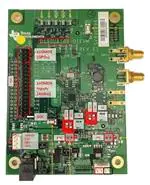
The SPA dongle is shown in Figure 3-1 given below. It is powered through USB and LED D1 will light up
RED when the SPA dongle is connected to a computer to indicate that the board is powered.
Figure 3-1. SPA Dongle
As shown in above Figure 3-1, I2C port of DS90UA101-Q1 (JP12) or DS90UA102-Q1 (JP9) evaluation
board must be connected to connector, JP8 on SPA dongle.
Refer Figure 1-3 and Figure 1-4 to find these connections.
3.2.1 EEPROM Setup of SPA Dongle
Once ALP software is running and SPA dongle is connected as stated above, the following steps are
required to communicate with a particular device. The example below sets up ALP for the DS90UA101Q1:
(1)
(2)
Not provided with the EVM.
Any I2C controller that supports clock stretching can be used.
Using I2C
SNLU147 – September 2013
Submit Documentation Feedback
Copyright © 2013, Texas Instruments Incorporated
13
�SPA Dongle Board
(3) (4)
www.ti.com
1. Under the Devices tab, there could be any device name at the place highlighted in RED as shown in
Figure 3-2.
Figure 3-2. Devices Tab
2. To communicate with a particular device, go to Tools > EEPROM Setup (Figure 3-3) .
14
Using I2C
SNLU147 – September 2013
Submit Documentation Feedback
Copyright © 2013, Texas Instruments Incorporated
�SPA Dongle Board
www.ti.com
(5) (6)
Figure 3-3. Tools Tab
3. Select the current device, which will be highlighted in BLUE as shown in Figure 3-4.
Using I2C
SNLU147 – September 2013
Submit Documentation Feedback
Copyright © 2013, Texas Instruments Incorporated
15
�SPA Dongle Board
(7) (8)
www.ti.com
Figure 3-4. ALP EEPROM Setup Window1
4. Select a device profile, which is DS90UA101 for example, and then click on Write EEPROM
(Figure 3-5).
16
Using I2C
SNLU147 – September 2013
Submit Documentation Feedback
Copyright © 2013, Texas Instruments Incorporated
�SPA Dongle Board
www.ti.com
(9) (10)
Figure 3-5. Selecting Device Profile
5. EEPROM Status will prompt as shown inFigure 3-6, press OK.
Figure 3-6. EEPROM Status
6. ALP EEPROM Setup window will show up with device name DS90UA101 as highlighted in Figure 3-7.
Press OK.
Using I2C
SNLU147 – September 2013
Submit Documentation Feedback
Copyright © 2013, Texas Instruments Incorporated
17
�SPA Dongle Board
(11) (12)
www.ti.com
Figure 3-7. ALP EEPROM Setup Window2
7. Under the Devices tab click on DS90UA101 to open up the DS90UA101-Q1 profile and its associated
tabs (Figure 3-8).
18
Using I2C
SNLU147 – September 2013
Submit Documentation Feedback
Copyright © 2013, Texas Instruments Incorporated
�SPA Dongle Board
www.ti.com
(13) (14)
Figure 3-8. ALP EEPROM Setup Window3
Using I2C
SNLU147 – September 2013
Submit Documentation Feedback
Copyright © 2013, Texas Instruments Incorporated
19
�Chapter 4
SNLU147 – September 2013
Additional Features
This section details the board configurations for additional features available on the evaluation boards.
4.1
Eye Monitor – CMLOUTP/N
The chipset features a differential eye monitor output to analyze the signal quality of the serial stream at
the receiving end of the transmission media. This eye monitor outputs the signal after it has gone through
the receiver's equalizer. Refer to Figure 4-1 below for the location of the CMLOUTP/N pads.
CMLOUTP
CMLOUTN
GND
Figure 4-1. Top view of CML access points on Deserializer Board
To use the Eye Monitor feature, mount SMA connectors on J3 and J4. Connector J3 connects CMLOUTP
(or TEST+) and J4 connects to CMLOUTN (or TEST-), which are present on left hand side of
DS90UA102-Q1 evaluation board. CMLOUTP/N must be enabled by register, 0x3F[4] = 0, to be able to
monitor the serial stream.
4.2
Power over Coaxiable Cable (PoC) - Board Configuration
The DS90UA101-Q1EVM and DS90UA102-Q1EVM were built to support the option of having power over
coax (PoC). In this configuration, power is applied to the Deserializer board, and this power source is also
sent across the same coaxiable cable used to send the serial data stream to power the Serializer board.
Additionally, the system configuration is changed to use only DOUT+ to RIN+, as shown below:
Normal System Configuration
PoC System Configuration
DOUT+
RIN+
DOUT-
RIN-
SER
20
DOUT+
DES
RIN+
SER
DES
DOUT-
Additional Features
50Q
50Q
RIN-
SNLU147 – September 2013
Submit Documentation Feedback
Copyright © 2013, Texas Instruments Incorporated
�Power over Coaxiable Cable (PoC) - Board Configuration
www.ti.com
To
•
•
•
use the PoC feature:
Mount R38 (0Ω) on DS90UA102-Q1EVM and R29 (0Ω) on DS90UA101-Q1EVM.
Terminate DOUT- (J3, SER) and RIN- (J7, DES) with 50Ω terminators.
Replace C19 on DS90UA101-Q1EVM with 0.047μF and replace C5 on DS90UA102-Q1EVM with
0.047μF.
The PoC system setup is shown below (Figure 4-2):
Figure 4-2. DS90UA101-Q1EVM & DS90UA102-Q1EVM in PoC Configuration
SNLU147 – September 2013
Submit Documentation Feedback
Additional Features
Copyright © 2013, Texas Instruments Incorporated
21
�Appendix A
SNLU147 – September 2013
DS90UA101-Q1EVM/DS90UA102-Q1EVM REV. E1
Schematics
This section shows the schematics of the DS90UA101-Q1EVM and DS90UA102-Q1EVM REV. E1.
22
DS90UA101-Q1EVM/DS90UA102-Q1EVM REV. E1 Schematics
Copyright © 2013, Texas Instruments Incorporated
SNLU147 – September 2013
Submit Documentation Feedback
�DS90UA101-Q1EVM REV. E1 Serializer Board Schematic
www.ti.com
A.1
DS90UA101-Q1EVM REV. E1 Serializer Board Schematic
A.1.1 DS90UA101-Q1 Serializer
1
2
3
4
Place L1, R28 about 2" from U1
1UF AT BOTTOM, AT VDD PIN TO DAP
0.1UF AT TOP, CLOSE TO VDD PIN
5
U2
C2
1UF
C3
0.1UF
C9
1UF
5
DOUTP_HSD_Z100
DOUTN_HSD_Z100
L1
C1
0.1UF
6
VDD1P8
4
1K@100MHz
C10
0.1UF
C11
1UF
GND
VDD5V
IO2
VCC
NC
GND IO1
1
2
3
C25
10UF
ESD-NO-STUFF
GND
VDD3P3
GND
GND
GND
ESD placed closed t o P1
A
C4
0.1UF
C5
1UF
C6
0.1UF
C12
1UF
PULL-UP/DOWN (GPO[3:0]) CLOSE TO JP1 HEADER
GND
14
11
VDDT
VDDCML
10
VDDPLL
25
28
VDDD
33
DAP
VDDIO
GPO3
1K
L2
POFL - SI NK SIDE
100UH
0.1UF
FAKRA_SMT_ROSENBERGER-NO-STUFF
SCK_OUT
19
20
21
22
23
24
26
27
29
30
31
32
1
2
3
GPI3
GPI2
GPI1
GPI0
DIN7
DIN6
DIN5
DIN4
DIN3
DIN2
DIN1
DIN0
BCK
LRCK
SCK
SCK_IN
DOUT+
DOUT-
L3
1
R30
0.1UF-NO-STUFF
13
0-NO-STUFF
12
6
2
C19
R32
10K
R80
R33
10K
49.9
GND
PDB
9
8
7
SDA
SCL
VDD5V
1
2
3
SW-PB
GND
L6
GND
VDD5V JP3
10UH-NOSTUFF
L7
S2
GND
4
3
GND
R34
10K
VDD1P8
1
2
C
GND
R38
0
1
2
3
10UH-NO-STUFF
GND
HEADER 3-NO-STUFF
SW DIP-2
SET
5
4
IDx
6
S1
1
2
4
3
RES0
C20
10UF
0-NO-STUFF
GPO3
GPO2
HEADER 3-NO-STUFF
100K
R39
4.7K-NO-STUFF
SW DIP-2
C26
0.1UF
C27
0.1UF
GND
IDX
R23
330
R42
49.9
VDD3P3
D1
D2
LED-orange
R24
10K
R25
0
TO external I2C Host
JP12
R36 0
VDD1P8
GND
1
2
3
4
SCL
SDA
0
R37
GND
0
C8
GPO3/2 = GPIO3/2 fr om DES set t o static high
GND
5PF-NO-STUFF
2
3
R26
4.7K
R27
4.7K
R44
49.9
VDDI2C
R35
LED-green
1
JP2
DS90UA101-Q1
R10
J3
SMA-bulkhead
DOUTN_Z50
0.1UF
R40
D
1
3
2
4
3
4
0-NO-STUFF
DOUTN_HSD_Z100 COILCRAFT_KA4909-NO-STUFF
VDD3P3
PDB
SET
RES0
Optional Header
DS90UA101-Q1_PAGE3.SCH
B
0.1UF-NO-STUFF
BUS AT 100MB/S, MATCH LENGTH TO 100MIL
R22
330
L5
5
R31
C18
U1
Power & Clock
DS90UA101-Q1_PAGE2.SCH
P1
ROSENBERGER_HSD_CON-NO-STUFF
DLW21SN261XQ2-NO-STUFF
C17
DOUTP_HSD_Z100
GPI3
GPI2
GPI1
GPI0
DIN7
DIN6
DIN5
DIN4
DIN3
DIN2
DIN1
DIN0
BCK
LRCK
SSC_CLK
J2
DOUTP_Z50
GPO3
GPO2
GPO1
GPO0
GND
SSC_CLK
J1
SMA-bulkhead
C16
S4
C
GND
3
GPO2
GPO0
0
5.6UH
R71
J 1 and J 2 sha r e the sa m e footpr int
J 1 and J 3: 625mil center -to-center
C24
4.7UF
HSD_PIN2_Z50
HSD_PIN4_Z50
HEADER 19X2
R21
GPO0
0-NO-STUFF
C23
0.1UF
2
8
10
12
14
16
18
20
22
24
26
28
30
32
34
36
38
B
15
16
17
18
R29
1K
L10
1K@100MHz
4
7
9
11
13
15
17
19
21
23
25
27
29
31
33
35
37
GPO3
GPO2
GPO1
GND
R28
C22
4.7UF
1
2
4
6
C15
22UF
R28,R71 TO LOWER Q
JP1
1
3
5
C14
1UF
C13
0.1UF
GND
GPO1
SCK_OUT
LRCK
BCK
DIN0
DIN1
DIN2
DIN3
DIN4
DIN5
DIN6
DIN7
GPI0
GPI1
GPI2
R1 R2 R3 R4 R5 R6 R7 R8 R9 R11 R12 R13 R14 R15 R16 R17 R18 R19 R20
10K 10K 10K 10K 10K 10K 10K 10K 10K 10K 10K 10K 10K 10K 10K 10K 10K 10K 10K
GPI3
GND
VDD5V
L4
GND
VDD3P3
C7
0.1UF
A
C13, 22 PLACED AT L3
VREMOTE
PULL-DOWN (GPI[3:0], DIN[7:0], BCK, LRCK, SCK) CLOSE TO IC
GND
D
HEADER 4
C21
5PF-NO-STUFF
GND
GND
4
SNLU147 – September 2013
Submit Documentation Feedback
5
6
DS90UA101-Q1EVM/DS90UA102-Q1EVM REV. E1 Schematics
Copyright © 2013, Texas Instruments Incorporated
23
�DS90UA101-Q1EVM REV. E1 Serializer Board Schematic
www.ti.com
A.1.2 Power to Serializer Board
1
2
3
4
5
6
A
A
Exter nal 5V IN
3.3V ADJ L DO
U3
VDD5V
JP4
4
1
2
3
4
VIN
VOUT
R48
10K-NO-STUFF
ADJ
C32
4 HEADER-NO-STUFF
1
VDD20V
JP14
1
2
3
4
16.5K-NO-STUFF
GND
R57
10K-NO-STUFF
C38
10UF-NO-STUFF
4 HEADER
GND
C37
0.1UF-NO-STUFF
5
C33
4.7UF-NO-STUFF
Exter nal 20V
U3_Pin3
R56
2
VEN
0.1UF-NO-STUFF
R49
0 - NO-STUFF
C28
22UF-NO-STUFF
U3_Pin3
3
LP38693MP-ADJ-NO-STUFF
GND
VDD1P8
SELECT 1.8V ADJ L DO OR 1.8V FIXED TO U1
1.8V ADJ L DO
U4
JP8
4
VIN
VOUT
R50
10K
B
R45
330
ADJ
1
VDD3P3
HEADER 3
4.53K
VEN
C39
C40
0.1UF 10UF
LP38693MP-ADJ
GPO2
GPO2 R62
2
100
GND
C45
10PF
5V TO 1.8V FIXED
U5
3
GND
VDD5V
GND
1
R52
10K-NO-STUFF
C29
10UF-NO-STUFF
VIN
SW
3
A
VCC
GND
Y
1
2
C47
0.1UF
1-Shot Latch to Monitor GPO 3 a n d G P O2 pulse L ow
C43
10UF-NO-STUFF
4
GND
U9
4
NC7SP04P5X
3
EN
FB
2
VDD3P3
5
L9
2.2uH-NO-STUFF
LPS3015-222ML
LM3671MF-1.8
R53
0 - No Stuff
0.1UF
NC
GND
5
B
SW-PB
C49
U7
1
D3
LED-RED
S3
R64
10K
R59
10K
GND
R51
0 - NO-STUFF
1
2
3
R58
2
5
C35
4.7UF
C34
0.1UF
3
CLRB
VDD3P3
CP
CLR
GND
VCC
D
Q
6
VDD3P3
5
ERR_GPO2
4
NC7SZ175P6X
C50
0.1UF
GND
R65
330
GND
GPO 3/2 = G P IO3/2 fr om DE S set t o static high
GPO3/2 pulsed low con sider ed as Er r or Condition for Back-Channel
GND
D4
LED-RED
LM3671MF-1.8-NO-STUFF
C
XT AL a n d SSC G en
GND
1
VDD3P3
L8
1K@100MHz
GPO3
C30
0.1UF
C31
1UF
C
U8
GPO3 R63
2
100
C46
10PF
C36
3
GND
R46
10K
NC
VDD3P3
A
VCC
GND
Y
GND
5
U10
4
1
NC7SP04P5X
2
GND
0.1UF
GND
3
GND
1=OSC EN
C48
0.1UF
X1
1
2
R47
0-NO-STUFF
ENABLE
GND
VCC
XTAL
OUT
U6
4
OSC_OUT
3
1
2
3
4
48.000MHz
R54
0
GND
GPO0 XOUT
VSS
VDD
S1
FSEL
S0 MODOUT
CP
CLR
GND
VCC
D
Q
6
VDD3P3
5
ERR_GPO3
4
NC7SZ175P6X
C51
0.1UF
GND
8
7
6
5
R66
330
GND
SSC_CLK
SSC_CLK
D5
LED-red orange
CY25814-NO-STUFF
JP5
1
2
R55
0
S0
S1
FSEL
HDR_2-NO-STUFF GND
GND
VDD3P3
D
D
XTAL: SSC-GEN
25MHz: CY25812, x2 = 50MHz
25MHz: CY25814, x4 = 100MHz
JP6
JP7
1
2
3
1
2
3
HEADER 3-NO-STUFF
HEADER 3-NO-STUFF
JP9
1
2
3
HEADER 3-NO-STUFF
GND
1
24
2
3
4
DS90UA101-Q1EVM/DS90UA102-Q1EVM REV. E1 Schematics
5
6
SNLU147 – September 2013
Submit Documentation Feedback
Copyright © 2013, Texas Instruments Incorporated
�DS90UA101-Q1EVM REV. E1 Serializer Board Schematic
www.ti.com
A.1.3 Optional Header for Serializer Board
1
2
3
4
5
6
Optiona l Header
A
A
JP10
GPI0
DIN6
DIN4
DIN2
R67
0-NO-STUFF
0-NO-STUFF
R69
0-NO-STUFF
0-NO-STUFF
R68
R70
BCK
LRCK
1
3
5
7
9
11
13
15
17
19
21
23
25
27
29
31
R72
0-NO-STUFF
0-NO-STUFF
SCK_IN
R73
VDD5V
GPI2
R75
0-NO-STUFF
R76
2
4
6
8
10
12
14
16
18
20
22
24
26
28
30
32
0-NO-STUFF
GPI1
R77
0-NO-STUFFDIN7
0-NO-STUFF
DIN5
R79
0-NO-STUFFDIN3
R78
R82
R81
0-NO-STUFFSDA
0-NO-STUFF
SCL
R83
0-NO-STUFF
GPO1
R84
0-NO-STUFF
GPI3
HEADER 16X2-NO-STUFF
B
B
NO-STUFF: J P10, R67-70, 72-79, 81-84
BUS AT 100MB/S, MATCH LENGTH TO 500MIL JP1 TO JP10
GND
R104
SCK_IN
R105
SCK_OUT_BYPASS
SCK_IN
SCK_OUT
0
0
R107
SCK_OUT
R108
SCK
SCK_U20
0_OPEN
0_OPEN
Layout Note: R104 Closer to JP10 pin 17 ,
VDD3P3
L15
C
2.2UH-NO-STUFF
C
C102
0.01UF-NO-STUFF
C103
10UF-NO-STUFF
0.1UF-NO-STUFF
C101
U20
S_SCK
SCK
S_SCK
1
SCK
2
3
4
FBIN
VDD
IN
OUT2
GND
OUT1
FS0
FS1
GND
22 Ohm-NO-STUFF
7
8
R106
SCK_OUT_FREQ_MULT
R101
SCK_U20
0-NO-STUFF
R102
6
S_SCK
SCK_U20
S_SCK
22 Ohm-NO-STUFF
5
CY2302-NO-STUFF
GND
GND
D
D
1
2
3
4
SNLU147 – September 2013
Submit Documentation Feedback
5
6
DS90UA101-Q1EVM/DS90UA102-Q1EVM REV. E1 Schematics
Copyright © 2013, Texas Instruments Incorporated
25
�DS90UA101-Q1EVM REV. E1 Serializer Board Schematic
www.ti.com
A.1.4 Buck Regulator on Serializer board
1
2
3
4
5
6
A
A
TPS65320 20V TO 5V BUCK REGULATOR
B
VIN_LDO
3
B
BOOT
1
C54
0.1UF
C0402
L12
VDD20V
1
2
3
SW
C52
4.7uF_50V
C1206
MBRS1540T3
RAPC722
C56
22uF
C1206
C57
22uF
C1206
C66
0.1uF_50V
C0603
GND
GND
GND
C55
20uF
C1206
XFL4020-472ME
2
GND
VDD20V
R93
0_DNL
R0603
R91
10K
R0603
8
7
R92
10K
R0603
Csn
EN2
FB1
D6
MBRS1540T3
C61
TBD
C0402
EN1
9
LDO_OUT
13
15
Sgnd
GND
C
VDD3P3
GND
JP13
GND
4
C63
10UF
C0805
C64
0.1UF
C0402
C65
0.1UF
C0402
U3_Pin3
1
2
3
U3_Pin3
HEADER 3
5
GND
TP2
EPAD
nRST
GND
NO-STUFF
R87
34K
R0603
FB2
GND
R90
5.69K
R0603
TP1
C59
12pF
C0402
SS
78.13nF-NO-STUFF
C0402
GND
C62
0.1UF
C0402
R88
10.5K
R0603
GND
1
10
C53
C58
3.9nF
C0402
12
RT/CLK
R85
52.45K
R0603
R89
30K
R0603
C60
22uF
C1206
GND
R86
20K
R0603
COMP
VDD5V
Pgnd
11
R94
0_DNL
R0603 GND
GND
R96
TBD
R0603
Rsn
TPS65320-Q
GND
C
VIN
1
1
2
3
XFL4020-472ME
L13
4.7uH
D7
JP11
R41
0
R2512
4.7uH
14
6
NO-STUFFGND
U21
TPS65320_QPWPRQ1
D
D
1
26
2
3
4
DS90UA101-Q1EVM/DS90UA102-Q1EVM REV. E1 Schematics
5
6
SNLU147 – September 2013
Submit Documentation Feedback
Copyright © 2013, Texas Instruments Incorporated
�DS90UA102-Q1EVM REV. E1 Deserializer Board Schematic
www.ti.com
A.2
DS90UA102-Q1EVM REV. E1 Deserializer Board Schematic
A.2.1 DS90UA102-Q1 Deserializer
1
2
3
4
5
Power & bypass
DS90UA102-Q1-PAGE2.SCH
PULL-UP PLACED NEAR HEADER
U2
5
RIN0P_HSD_ZDIFF
RIN0N_HSD_ZDIFF
R1 R2 R3 R4 R5 R6 R7 R8 R9 R13 R14 R15 R16 R17 R18 R19 R20
10K 10K 10K 10K 10K 10K 10K 10K 10K 10K 10K 10K 10K 10K 10K 10K 10K
VDD5V_A
IO2
4
GND_A
6
1
2
3
VCC
NC
IO1
GND
GND_A
C12
10UF
R49
49.9-NO-STUFF
R48
49.9-NO-STUFF
ESD-NO-STUFF
GND_A
Optional header
DS90UA102-Q1-PAGE3.SCH
ESD placed closed t o P1
VDDR
VDDPLL
VDDCML
LOCK
VDD3P3_A
PASS
SCKO
LRCK
DOUT0
BCK
DOUT1
DOUT2
DOUT3
DOUT4
DOUT5
DOUT6
DOUT7
GPO0
GPO1
GPO3
GPO2
GND_A
A
C2
0.1UF
1K@100MHz
C3
4.7UF
C13
0.1UF
L6
B
SCKO
LRCK
BCK
DOUT0
DOUT1
DOUT2
DOUT3
DOUT4
DOUT5
DOUT6
DOUT7
GPO0
GPO1
GPO2
GPO3
8
9
10
11
12
13
14
15
16
18
19
21
22
23
24
GPIO0
GPIO1
GPIO2
GPIO3
25
26
27
28
RINSCK
LRCK
BCK
DOUT0
DOUT1
DOUT2
DOUT3
DOUT4
DOUT5
DOUT6
DOUT7
GPO0
GPO1
GPO2
GPO3
GPIO0
GPIO1
GPIO2
GPIO3
TEST-
33
38
TESTP_DIFF100
39
TESTN_DIFF100
BUS AT 100MB/S, MATCH LENGTH TO 100MIL
C
VDD3P3_A
GND_A
JP1, JP8 SEPARATE BY 0.1 INCH
7
20
29
VDDIO
VDDIO
VDDIO
100UH
R83
R87
1K
1K
GND_A
1
RIN1P_Z50
J1
SMA-bulkhead-NO-STUFF
RIN1N_Z50
J2
SMA-bulkhead-NO-STUFF
GND_A
J3
GND_A
SMA_R_EDGE-NO-STUFF
0.1UF
C9
0.1UF
J4
SMA_R_EDGE-NO-STUFF
SW-PB
C10
10UF
S1
PDB_RX
RES0_RES_RX
RES0_TESTEN
RES0_SEL
OSS_SEL
OEN
BISTEN
30
43
44
46
4
5
6
J5
R74 IS A DUMMY PAD
S4
14
13
12
11
10
9
8
J 1 and J 2: 625mil center -to-center
J 1 and J 3 sha r e the sa m e footpr int
GND_A
1
2
3
4
5
6
7
VDD1P8_A
GND_A
C
R39
10K
S2
6
5
4
37
SW DIP-7
R45
1
2
3
11K-NO-STUFF
R46
SDA
SCL
GND_A
SW DIP-3
3K-NO-STUFF
R107
1
2
RES0
IDx
34
35
47
48
PASS
LOCK
RES0
2
L2
5.6UH
R30
10K
PDB
RES0
RES0
RES0
OSS_SEL
OEN
BISTEN
C8
J7
SMA-bulkhead
B
GND_A
FAKRA_SMT_ROSENBERGER-NO-STUFF
L9
0-NO-STUFF
49.9
L4
5
R38
R74
C7
HEADER 4X2
DS90UA102-Q1
2
1
6
0-NO-STUFF
RIN0N_HSD_ZDIFF COILCRAFT_KA4909-NO-STUFF
0.1UF-NO-STUFF
32
VDD3P3_A
U1
J6
SMA-bulkhead
4
R37
0.1UF-NO-STUFF
TEST+
2
4
6
8
42
C6
HEADER 15X2
JP8
1
3
5
7
0-NO-STUFF
0.1UF
RES1
L1
3
R36
41
C5
RES1
HEADER 3-NO-STUFF
GND_A
4
2
4
6
8
10
12
14
16
18
20
22
24
26
28
30
1
2
3
DLW21SN261XQ2 - NO-STUFF
RIN0P_HSD_ZDIFF
3
JP1
2.7UH-NO-STUFF
GND_A
C4
0.1UF
RIN+
1
3
5
7
9
11
13
15
17
19
21
23
25
27
29
VFEED
40
3
POFL - SOURCE SIDE
VDDR
31
GND_A
VDDCML
VDDCML
VDDPLL
45
17
36
VDDR
VDDD
49
DAP
GPIO3
GPIO2
GPIO1
GPIO0
RES0_RES_RX
OEN
OSS_SEL
RES0_TESTEN
RES0_SEL
BISTEN
R24 R25 R26 R27
10K 10K 10K 10K
A
1
2
3
HEADER 3-NO-STUFF
JP4
C14
4.7UF
GND_A
R10 R11 R12 R21 R22 R23
10K 10K 10K 10K 10K 10K
JP3
L5
2.7UH-NO-STUFF
VDD5V_A
L3
VDD3P3_A
C16
VDD5V_A
0.1UF-NO-STUFF
C15
0.1UF-NO-STUFF
R47
0
0
GND_A
PASS
LOCK
GND_A
JP9 >0.3 INCH ON EAST SIDE OF JP8
JP2
1
3
VDD3P3_A
IDX0
PASS
LOCK
R28
330
2
4
R40
R29
330
R31 R32
10K 0
D2
LED-orange
SCL_A
SDA_A
0
R42
R33 R34
0
10K
0
GND_A
D1
JP9
R41 0
HEADER 2X2
D
VDDI2C_A
C1
VDD1P8_A
R35
4.7K
R43
4.7K
1
2
3
4
GND_A HEADER 4
D
C11
5PF-NO-STUFF
LED-green
GND_A
GND_A
5PF-NO-STUFF
GND_A
GND_A
1
2
3
4
SNLU147 – September 2013
Submit Documentation Feedback
5
6
DS90UA101-Q1EVM/DS90UA102-Q1EVM REV. E1 Schematics
Copyright © 2013, Texas Instruments Incorporated
27
�DS90UA102-Q1EVM REV. E1 Deserializer Board Schematic
www.ti.com
A.2.2 Power to Deserializer Board
1
2
3
JP5
5
4
VIN
VOUT
R54
10K-NO-STUFF
ADJ
C21
Exter na l 5V IN
1
C22
0.1UF-NO-STUFF
R55
0 -NO-STUFF
VEN
3
U3_Pin3
VDD3P3_A
VDD1P8_A
C38
0.1UF
16.5K-NO-STUFF
R60
10K-NO-STUFF
C28
10UF-NO-STUFF
C39
1UF
C44
0.1UF
R50
330
VIN
VOUT
R56
10K
ADJ
C62
10UF
C41
1UF
C50
0.1UF
C24
4.7UF
R57
0-NO-STUFF
1
2
3
R61
2
For VDDCML
C43
1UF
C53
0.1UF
VIN
GND_A
C56
0.1UF
SELECT 1.8V ADJ LDO OR 1.8V FIXED
L8
SW
5
VDDPLL
B
C59
1UF
R69
C46
0.1UF
FB
2
GND_A
C58
0.1UF
GND_A
L7
2.2uH-NO-STUFF
LPS3015-222ML
EN
R58
0 - No Stuff
C57
1UF
5V TO 1.8V FIXED
LM3671MF-1.8
3
C55
22UF
For VDDD
C29
C30
0.1UF 10UF
U5
1
C54
1UF
GND_A
HEADER 3
4.53K
R62
10K
1K@100MHz
R51
10K-NO-STUFF
For VDDCML
GND_A
C42
0.1UF
GND_A
C18
10UF-NO-STUFF
C52
22UF
For VDDIO
LP38693MP-ADJ
GND_A
A
C51
1UF
GND_A
5
D3
LED-RED
C23
0.1UF
VEN
For VDDR
GND_A
C40
0.1UF
VDD3P3_A
3
GND
1
C49
1UF
GND_A
JP6
4
VDDCML
C48
0.1UF
For VDDIO
VDD1P8_A
1.8V ADJ LDO
U4
0
C45
1UF
VDD3P3_A
C27
0.1UF-NO-STUFF
LP38693MP-ADJ-NO-STUFF
GND_A
R68
For VDDIO
5
4.7UF-NO-STUFF
VDD3P3_A
U3_Pin3
R59
2
GND
C17
22UF-NO-STUFF
4 HEADER-NO-STUFF
B
6
VDD5V_A
1
2
3
4
A
4
PLACE 0.1UF TOP SIDE NEAR TO VDD PIN OF U1
PLACE 1UF OR 22UF ON BOTTOM SIDE
3.3V ADJ LDO
U3
C47
1UF
0
VDDR
C60
0.1UF
C61
1UF
C33
10UF-NO-STUFF
4
GND_A
GND
PLACE R68-69, L8 ABOUT 2 INCH FROM U1
LM3671MF-1.8-NO-STUFF
GND_A
VDD3P3_A
U6
C
1
PASS
R52
PASS
2
100
C19
3
10PF-NO-STUFF GND
GND_A
NC7SP04P5X
GND_A
SW-PB
C35
10K
NC
A
S3
R65
C
Exter na l 20V
VDD3P3_A
VCC
Y
VDD20V_A
5
U7
4
1
2
3
C25
0.1UF
CP
GND
0.1UF
CLR
VCC
D
Q
GND_A
JP10
6
1
2
3
4
VDD3P3_A
5
D4
ERR_PASS
4
R66
330
NC7SZ175P6X
CLRB_A
1-Shot Latch t o monit or LO C K and PASS pulse Low
GND_A
4 HEADER
LED-RED
GND_A
GND_A
C36
0.1UF
GND_A
U8
1
LOCK
LOCK
R53
2
100
D
NC
A
C20
3
10PF-NO-STUFF GND
NC7SP04P5X
GND_A
GND_A
VDD3P3_A
VCC
Y
5
U9
4
1
2
3
C26
0.1UF
CP
CLR
GND
VCC
D
Q
6
VDD3P3_A
D
5
D5
ERR_LOCK
4
R67
330
NC7SZ175P6X
LED-red orangeGND_A
C37
0.1UF
GND_A
GND_A
1
28
2
3
4
DS90UA101-Q1EVM/DS90UA102-Q1EVM REV. E1 Schematics
5
6
SNLU147 – September 2013
Submit Documentation Feedback
Copyright © 2013, Texas Instruments Incorporated
�DS90UA102-Q1EVM REV. E1 Deserializer Board Schematic
www.ti.com
A.2.3 Optional Header for Deserializer Board
1
2
3
4
5
6
A
A
Optiona l Header
JP7
GPO0
DOUT6
DOUT4
DOUT2
BCK
LRCK
SCKO
B
R71
R73
R76
GPO2
R70
0-NO-STUFF
0-NO-STUFF
R72
0-NO-STUFF
0-NO-STUFF
R75
0-NO-STUFF
0-NO-STUFF
R77
0-NO-STUFF
R78
0-NO-STUFF
1
3
5
7
9
11
13
15
17
19
21
23
25
27
29
31
R79
2
4
6
8
10
12
14
16
18
20
22
24
26
28
30
32
0-NO-STUFF
GPO1
R80 0-NO-STUFFDOUT7
DOUT5
R81 0-NO-STUFF
R82
0-NO-STUFFDOUT3
R84
0-NO-STUFFSDA_A
SCL_A
0-NO-STUFF
R85
B
R86
0-NO-STUFF
GPO3
HEADER 16X2-NO-STUFF
GND_A
NO-STUFF: JP7, R70-73, R75-82, R84-86
C
C
D
D
1
2
3
4
SNLU147 – September 2013
Submit Documentation Feedback
5
6
DS90UA101-Q1EVM/DS90UA102-Q1EVM REV. E1 Schematics
Copyright © 2013, Texas Instruments Incorporated
29
�DS90UA102-Q1EVM REV. E1 Deserializer Board Schematic
www.ti.com
A.2.4 Buck Regulator on Deserializer Board
1
2
3
4
5
6
A
A
TPS65320 20V TO 5V BUCK REGULATOR
B
VIN_LDO
3
B
BOOT
1
C73
0.1UF
C0402
VDD5V_A
L12
VDD20V_A
MBRS1540T3
RAPC722
C63
4.7uF_50V
C1206
C64
22uF
C1206
C65
22uF
C1206
C77
0.1uF_50V
C0603
GND_A
GND_A
GND_A
14
C69
20uF
C1206
XFL4020-472ME
2
GND_A
VDD20V_A
VIN
R97
0_DNL
R0603
R96
10K
R0603
8
C
EN2
FB1
9
LDO_OUT
10
C
VDD3P3_A
GND_A
JP12
GND_A
C66
10UF
C0805
C67
0.1UF
C0402
C68
0.1UF
C0402
U3_Pin3
1
2
3
U3_Pin3
HEADER 3
5
NO-STUFF
TP2
EPAD
Sgnd
NO-STUFF
4
GND
15
GND_A
C76
12pF_DNI
C0402
R102
34K
R0603
FB2
13
GND_A
R106
5.69K
R0603
TP1
12
SS
78.13nF
C0402
GND_A
R103
10.5K
R0603
GND_A
1
GND_A
C75
3.9nF
C0402
RT/CLK
R100
52.45K
R0603
GND_A
C71
0.1UF
C0402
GND_A
R104
20K
R0603
COMP
R105
30K
R0603
C70
22uF
C1206
Pgnd
11
R99
0_DNL
R0603 GND_A
C72
D6
MBRS1540T3
C74
TBD
C0402
EN1
7
R98
10K
R0603
Csn
TPS65320-Q
GND_A
R101
TBD
R0603
Rsn
1
1
2
3
1
2
3
SW
XFL4020-472ME
L13
4.7uH
D7
JP11
R108
0
R2512
4.7uH
nRST
6
GND_A
U21
TPS65320_QPWPRQ1
D
D
1
30
2
3
4
DS90UA101-Q1EVM/DS90UA102-Q1EVM REV. E1 Schematics
5
6
SNLU147 – September 2013
Submit Documentation Feedback
Copyright © 2013, Texas Instruments Incorporated
�Appendix B
SNLU147 – September 2013
DS90UA101-Q1EVM & DS90UA102-Q1EVM REV. E1 Bill of
Materials
B.1
DS90UA101-Q1 Serializer Board BOM
Table B-1. DS90UA101-Q1 Serializer Board BOM
Part Type
Reference
Designator
Footprint
Description
Part Field
No-Stuff
Designator
0-NO-STUFF
R82
402
SMT R, +-1%
Panasonic ERJ2GE0R00X, 0.1W,
DigiKey P0.0JCTND
No-Stuff
0-NO-STUFF
R81
402
SMT R, +-1%
Panasonic ERJ2GE0R00X, 0.1W,
DigiKey P0.0JCTND
No-Stuff
0-NO-STUFF
R79
402
SMT R, +-1%
Panasonic ERJ2GE0R00X, 0.1W,
DigiKey P0.0JCTND
No-Stuff
0-NO-STUFF
R84
402
SMT R, +-1%
Panasonic ERJ2GE0R00X, 0.1W,
DigiKey P0.0JCTND
No-Stuff
0-NO-STUFF
R68
402
SMT R, +-1%
Panasonic ERJ2GE0R00X, 0.1W,
DigiKey P0.0JCTND
No-Stuff
0-NO-STUFF
R83
402
SMT R, +-1%
Panasonic ERJ2GE0R00X, 0.1W,
DigiKey P0.0JCTND
No-Stuff
0
R35
402
SMT R, +-1%
Panasonic ERJ2GE0R00X, 0.0
ohm, 0.1W, 0402,
Digikey P0.0JCTND
0
R25
402
SMT R, +-1%
Panasonic ERJ2GE0R00X, 0.0
ohm, 0.1W, 0402,
Digikey P0.0JCTND
0-NO-STUFF
R10
402
SMT R, +-1%
Panasonic ERJ2GE0R00X, 0.0
ohm, 0.1W, 0402,
Digikey P0.0JCTND
0
R54
402
SMT R, +-1%
Panasonic ERJ2GE0R00X, 0.1W,
DigiKey P0.0JCTND
0-NO-STUFF
R78
402
SMT R, +-1%
Panasonic ERJ2GE0R00X, 0.1W,
DigiKey P0.0JCTND
SNLU147 – September 2013
Submit Documentation Feedback
No-Stuff
No-Stuff
DS90UA101-Q1EVM & DS90UA102-Q1EVM REV. E1 Bill of Materials
Copyright © 2013, Texas Instruments Incorporated
31
�DS90UA101-Q1 Serializer Board BOM
www.ti.com
Table B-1. DS90UA101-Q1 Serializer Board BOM (continued)
32
0-NO-STUFF
R77
402
SMT R, +-1%
Panasonic ERJ2GE0R00X, 0.1W,
DigiKey P0.0JCTND
No-Stuff
0-NO-STUFF
R76
402
SMT R, +-1%
Panasonic ERJ2GE0R00X, 0.1W,
DigiKey P0.0JCTND
No-Stuff
0-NO-STUFF
R67
402
SMT R, +-1%
Panasonic ERJ2GE0R00X, 0.1W,
DigiKey P0.0JCTND
No-Stuff
100K
R38
805
SMT R, +-1%
Panasonic ERJ6ENF1003V, 100K
ohm, 0.125W, 0805,
Digikey P100KCCTND
0-NO-STUFF
R73
402
SMT R, +-1%
Panasonic ERJ2GE0R00X, 0.1W,
DigiKey P0.0JCTND
No-Stuff
0-NO-STUFF
R69
402
SMT R, +-1%
Panasonic ERJ2GE0R00X, 0.1W,
DigiKey P0.0JCTND
No-Stuff
0-NO-STUFF
R70
402
SMT R, +-1%
Panasonic ERJ2GE0R00X, 0.1W,
DigiKey P0.0JCTND
No-Stuff
0-NO-STUFF
R75
402
SMT R, +-1%
Panasonic ERJ2GE0R00X, 0.1W,
DigiKey P0.0JCTND
No-Stuff
0-NO-STUFF
R72
402
SMT R, +-1%
Panasonic ERJ2GE0R00X, 0.1W,
DigiKey P0.0JCTND
No-Stuff
0-NO-STUFF
R31
603
SMD R, +-1%, 0603 Panasonic ERJNo-Stuff
3GEY0R00V, 0ohm,
0603, DigiKey#
P0.0GCT-ND
0-NO-STUFF
R30
603
SMD R, +-1%, 0603 Panasonic ERJNo-Stuff
3GEY0R00V, 0ohm,
0603, DigiKey#
P0.0GCT-ND
0-NO-STUFF
R53
603
SMD R, +-1%, 0603 Panasonic ERJNo-Stuff
3GEY0R00V, 0ohm,
0603, DigiKey#
P0.0GCT-ND
0-NO-STUFF
R29
603
SMD R, +-1%, 0603 Panasonic ERJNo-Stuff
3GEY0R00V, 0ohm,
0603, DigiKey#
P0.0GCT-ND
0
R36
603
SMD R, +-1%, 0603 Panasonic ERJ3GEY0R00V, 0ohm,
0603, DigiKey#
P0.0GCT-ND
0
R37
603
SMD R, +-1%, 0603 Panasonic ERJ3GEY0R00V, 0ohm,
0603, DigiKey#
P0.0GCT-ND
DS90UA101-Q1EVM & DS90UA102-Q1EVM REV. E1 Bill of Materials
Copyright © 2013, Texas Instruments Incorporated
SNLU147 – September 2013
Submit Documentation Feedback
�DS90UA101-Q1 Serializer Board BOM
www.ti.com
Table B-1. DS90UA101-Q1 Serializer Board BOM (continued)
0
R55
402
SMT R, +-1%
Panasonic ERJ2GE0R00X, 0.1W,
DigiKey P0.0JCTND
0-NO-STUFF
R47
402
SMT R, +-1%
Panasonic ERJ2GE0R00X, 0.1W,
DigiKey P0.0JCTND
0
R21
402
SMT R, +-1%
Panasonic ERJ2GE0R00X, 0.0
ohm, 0.1W, 0402,
Digikey P0.0JCTND
0-NO-STUFF
R51
603
SMD R, +-1%, 0603 Panasonic ERJNo-Stuff
3GEY0R00V, 0ohm,
0603, DigiKey#
P0.0GCT-ND
0-NO-STUFF
R49
603
SMD R, +-1%, 0603 Panasonic ERJNo-Stuff
3GEY0R00V, 0ohm,
0603, DigiKey#
P0.0GCT-ND
0.1UF
C48
402
Chip cap, X7R,
0402
16V, 10%, X7R,
Murata
GRM155R71C104K
A88D, Digikey 4903261-1-ND
0.1UF
C50
402
Chip cap, X7R,
0402
16V, 10%, X7R,
Murata
GRM155R71C104K
A88D, Digikey 4903261-1-ND
0.1UF-NO-STUFF
C32
402
Chip cap, X7R,
0402
16V, 10%, X7R,
No-Stuff
Murata
GRM155R71C104K
A88D, Digikey 4903261-1-ND
0.1UF
C34
402
Chip cap, X7R,
0402
16V, 10%, X7R,
Murata
GRM155R71C104K
A88D, Digikey 4903261-1-ND
0.1UF
C39
402
Chip cap, X7R,
0402
16V, 10%, X7R,
Murata
GRM155R71C104K
A88D, Digikey 4903261-1-ND
0.1UF-NO-STUFF
C37
402
Chip cap, X7R,
0402
16V, 10%, X7R,
No-Stuff
Murata
GRM155R71C104K
A88D, Digikey 4903261-1-ND
0.1UF
C13
402
Chip cap, X7R,
0402
16V, 10%, X7R,
Murata
GRM155R71C104K
A88D, Digikey 4903261-1-ND
0.1UF
C47
402
Chip cap, X7R,
0402
16V, 10%, X7R,
Murata
GRM155R71C104K
A88D, Digikey 4903261-1-ND
SNLU147 – September 2013
Submit Documentation Feedback
No-Stuff
DS90UA101-Q1EVM & DS90UA102-Q1EVM REV. E1 Bill of Materials
Copyright © 2013, Texas Instruments Incorporated
33
�DS90UA101-Q1 Serializer Board BOM
www.ti.com
Table B-1. DS90UA101-Q1 Serializer Board BOM (continued)
34
0.1UF
C30
402
Chip cap, X7R,
0402
16V, 10%, X7R,
Murata
GRM155R71C104K
A88D, Digikey 4903261-1-ND
0.1UF
C10
402
Chip cap, X7R,
0402
16V, 10%, X7R,
Murata
GRM155R71C104K
A88D, Digikey 4903261-1-ND
0.1UF
C4
402
Chip cap, X7R,
0402
16V, 10%, X7R,
Murata
GRM155R71C104K
A88D, Digikey 4903261-1-ND
0.1UF
C23
402
Chip cap, X7R,
0402
16V, 10%, X7R,
Murata
GRM155R71C104K
A88D, Digikey 4903261-1-ND
0.1UF
C1
402
Chip cap, X7R,
0402
16V, 10%, X7R,
Murata
GRM155R71C104K
A88D, Digikey 4903261-1-ND
0.1UF
C7
402
Chip cap, X7R,
0402
16V, 10%, X7R,
Murata
GRM155R71C104K
A88D, Digikey 4903261-1-ND
0.1UF
C6
402
Chip cap, X7R,
0402
16V, 10%, X7R,
Murata
GRM155R71C104K
A88D, Digikey 4903261-1-ND
0.1UF
C3
402
Chip cap, X7R,
0402
16V, 10%, X7R,
Murata
GRM155R71C104K
A88D, Digikey 4903261-1-ND
0.1UF
C36
402
Chip cap, X7R,
0402
16V, 10%, X7R,
Murata
GRM155R71C104K
A88D, Digikey 4903261-1-ND
0.1UF
C49
402
Chip cap, X7R,
0402
16V, 10%, X7R,
Murata
GRM155R71C104K
A88D, Digikey 4903261-1-ND
0.1UF
C51
402
Chip cap, X7R,
0402
16V, 10%, X7R,
Murata
GRM155R71C104K
A88D, Digikey 4903261-1-ND
0.1UF
C27
603
Chip cap, X7R,
0603
Murata
GRM188R72A104K
A35D, 0.1UF, +10%, 100V, X7R,
DigiKey# 490-32851-ND
DS90UA101-Q1EVM & DS90UA102-Q1EVM REV. E1 Bill of Materials
Copyright © 2013, Texas Instruments Incorporated
SNLU147 – September 2013
Submit Documentation Feedback
�DS90UA101-Q1 Serializer Board BOM
www.ti.com
Table B-1. DS90UA101-Q1 Serializer Board BOM (continued)
0.1UF
C26
603
Chip cap, X7R,
0603
Murata
GRM188R72A104K
A35D, 0.1UF, +10%, 100V, X7R,
DigiKey# 490-32851-ND
0.1UF-NO-STUFF
C17
603
Chip cap, X7R,
0603
Murata
GRM188R72A104K
A35D, 0.1UF, +10%, 100V, X7R,
DigiKey# 490-32851-ND
No-Stuff
0.1UF-NO-STUFF
C18
603
Chip cap, X7R,
0603
Murata
GRM188R72A104K
A35D, 0.1UF, +10%, 100V, X7R,
DigiKey# 490-32851-ND
No-Stuff
1K@100MHz
L1
603
Ferrite Bead
Murata, Ferrite
Bead, 1K
@100MHz,
BLM18AG102SN1D
, 0603, DigiKey#
490-1015-1-ND
1K@100MHz
L4
603
Ferrite Bead
Murata, Ferrite
Bead, 1K
@100MHz,
BLM18AG102SN1D
, 0603, DigiKey#
490-1015-1-ND
1K@100MHz
L8
603
Ferrite Bead
Murata, Ferrite
Bead, 1K
@100MHz,
BLM18AG102SN1D
, 0603, DigiKey#
490-1015-1-ND
1UF
C5
603
Chip cap, X7R,
0603
Murata,
GRM188R71E105K
A12x, 1UF, 10%,
25V, -55 to 125C,
DigiKey# 490-53071-ND
1UF
C11
603
Chip cap, X7R,
0603
Murata,
GRM188R71E105K
A12x, 1UF, 10%,
25V, -55 to 125C,
DigiKey# 490-53071-ND
1UF
C2
603
Chip cap, X7R,
0603
Murata,
GRM188R71E105K
A12x, 1UF, 10%,
25V, -55 to 125C,
DigiKey# 490-53071-ND
1UF
C12
603
Chip cap, X7R,
0603
Murata,
GRM188R71E105K
A12x, 1UF, 10%,
25V, -55 to 125C,
DigiKey# 490-53071-ND
1UF
C31
603
Chip cap, X7R,
0603
Murata,
GRM188R71E105K
A12x, 1UF, 10%,
25V, -55 to 125C,
DigiKey# 490-53071-ND
SNLU147 – September 2013
Submit Documentation Feedback
DS90UA101-Q1EVM & DS90UA102-Q1EVM REV. E1 Bill of Materials
Copyright © 2013, Texas Instruments Incorporated
35
�DS90UA101-Q1 Serializer Board BOM
www.ti.com
Table B-1. DS90UA101-Q1 Serializer Board BOM (continued)
36
1UF
C9
603
Chip cap, X7R,
0603
Murata,
GRM188R71E105K
A12x, 1UF, 10%,
25V, -55 to 125C,
DigiKey# 490-53071-ND
1UF
C14
603
Chip cap, X7R,
0603
Murata,
GRM188R71E105K
A12x, 1UF, 10%,
25V, -55 to 125C,
DigiKey# 490-53071-ND
2.2UH-NO-STUFF
L9
LPS3015-222ML
SMT inductor
CoilCraft, LPS3015- No-Stuff
222ML, 2.2UH+10%
5.6UH
L10
SMT inductor
CoilCraft, 1008PS562KL, 5.6UH+10%
10UH-NO-STUFF
L7
SMT inductor
CoilCraft, 1008PSNo-Stuff
103KL, 10UH+-10%
10UH-NO-STUFF
L6
SMT inductor
CoilCraft, 1008PSNo-Stuff
103KL, 10UH+-10%
4.7K-NO-STUFF
R39
805
SMT R, +-1%,805
Panasonic ERJ6GEYJ472V, 4.7K,
5%, 0.125W,
DigiKey#
P4.7KACT-ND
4.7K
R27
402
SMT R, +-1%
Panasonic ERJ2RKF4701X, 1%,
100ppm, 0.1W,
DigiKey
P4.70KLCT-ND
4.7K
R26
402
SMT R, +-1%
Panasonic ERJ2RKF4701X, 1%,
100ppm, 0.1W,
DigiKey
P4.70KLCT-ND
4.7UF
C35
805
Chip cap, X7R,
0805
Murata
GRM21BR71C475K
A73L, 4.7UF, 16V,
X7R, 0805, 10%,
DigiKey# 490-45221-ND
10UF-NO-STUFF
C29
805
Chip cap, X7R,
0805
Murata
No-Stuff
GRM21BR61C106K
E15L, 10UF, 10%,
16V, X5R, 0805,
DigiKey# 490-38861-ND
4.7UF-NO-STUFF
C33
805
Chip cap, X7R,
0805
Murata
No-Stuff
GRM21BR71C475K
A73L, 4.7UF, 16V,
X7R, 0805, 10%,
DigiKey# 490-45221-ND
4.7UF
C24
805
Chip cap, X7R,
0805
Murata
GRM21BR71C475K
A73L, 4.7UF, 16V,
X7R, 0805, 10%,
DigiKey# 490-45221-ND
DS90UA101-Q1EVM & DS90UA102-Q1EVM REV. E1 Bill of Materials
Copyright © 2013, Texas Instruments Incorporated
No-Stuff
SNLU147 – September 2013
Submit Documentation Feedback
�DS90UA101-Q1 Serializer Board BOM
www.ti.com
Table B-1. DS90UA101-Q1 Serializer Board BOM (continued)
4.7UF
C22
805
Chip cap, X7R,
0805
Murata
GRM21BR71C475K
A73L, 4.7UF, 16V,
X7R, 0805, 10%,
DigiKey# 490-45221-ND
4.53K
R58
603
SMT R, +-1%
Panasonic ERJ3EKF4531V, 1%,
100ppm, 0.1W,
DigiKey
P4.53KHCT-ND
4 HEADER-NOSTUFF
JP4
4 Pin Header
Molex, 1x4 header
pin, 0.1 pitch,
DigiKey# WM2702ND
5PF-NO-STUFF
C21
402
Chip cap, X7R,
0402
Murata
No-Stuff
GRM1555C1H5R0C
Z01D, 5pF+-0.25pF,
50V, NPO, DigiKey#
490-1274-1-ND
5PF-NO-STUFF
C8
402
Chip cap, X7R,
0402
Murata
No-Stuff
GRM1555C1H5R0C
Z01D, 5pF+-0.25pF,
50V, NPO, DigiKey#
490-1274-1-ND
10K
R7
402
SMT R, +-1%
10K+-5%, +200ppm/C,
Panasonic, ERJ2GEJ103X, 0402,
Digikey P10KJCTND
10K
R8
402
SMT R, +-1%
10K+-5%, +200ppm/C,
Panasonic, ERJ2GEJ103X, 0402,
Digikey P10KJCTND
10K
R32
402
SMT R, +-1%
10K+-5%, +200ppm/C,
Panasonic, ERJ2GEJ103X, 0402,
Digikey P10KJCTND
10K
R17
402
SMT R, +-1%
10K+-5%, +200ppm/C,
Panasonic, ERJ2GEJ103X, 0402,
Digikey P10KJCTND
10K
R33
402
SMT R, +-1%
10K+-5%, +200ppm/C,
Panasonic, ERJ2GEJ103X, 0402,
Digikey P10KJCTND
10K
R16
402
SMT R, +-1%
10K+-5%, +200ppm/C,
Panasonic, ERJ2GEJ103X, 0402,
Digikey P10KJCTND
SNLU147 – September 2013
Submit Documentation Feedback
No-Stuff
DS90UA101-Q1EVM & DS90UA102-Q1EVM REV. E1 Bill of Materials
Copyright © 2013, Texas Instruments Incorporated
37
�DS90UA101-Q1 Serializer Board BOM
www.ti.com
Table B-1. DS90UA101-Q1 Serializer Board BOM (continued)
38
10K
R14
402
SMT R, +-1%
10K+-5%, +200ppm/C,
Panasonic, ERJ2GEJ103X, 0402,
Digikey P10KJCTND
10K
R46
402
SMT R, +-1%
10K+-5%, +200ppm/C,
Panasonic, ERJ2GEJ103X, 0402,
Digikey P10KJCTND
10K
R15
402
SMT R, +-1%
10K+-5%, +200ppm/C,
Panasonic, ERJ2GEJ103X, 0402,
Digikey P10KJCTND
10K
R13
402
SMT R, +-1%
10K+-5%, +200ppm/C,
Panasonic, ERJ2GEJ103X, 0402,
Digikey P10KJCTND
10K
R9
402
SMT R, +-1%
10K+-5%, +200ppm/C,
Panasonic, ERJ2GEJ103X, 0402,
Digikey P10KJCTND
10K
R11
402
SMT R, +-1%
10K+-5%, +200ppm/C,
Panasonic, ERJ2GEJ103X, 0402,
Digikey P10KJCTND
10K
R12
402
SMT R, +-1%
10K+-5%, +200ppm/C,
Panasonic, ERJ2GEJ103X, 0402,
Digikey P10KJCTND
10K
R3
402
SMT R, +-1%
10K+-5%, +200ppm/C,
Panasonic, ERJ2GEJ103X, 0402,
Digikey P10KJCTND
10K
R19
402
SMT R, +-1%
10K+-5%, +200ppm/C,
Panasonic, ERJ2GEJ103X, 0402,
Digikey P10KJCTND
10K
R20
402
SMT R, +-1%
10K+-5%, +200ppm/C,
Panasonic, ERJ2GEJ103X, 0402,
Digikey P10KJCTND
10K
R2
402
SMT R, +-1%
10K+-5%, +200ppm/C,
Panasonic, ERJ2GEJ103X, 0402,
Digikey P10KJCTND
DS90UA101-Q1EVM & DS90UA102-Q1EVM REV. E1 Bill of Materials
Copyright © 2013, Texas Instruments Incorporated
SNLU147 – September 2013
Submit Documentation Feedback
�DS90UA101-Q1 Serializer Board BOM
www.ti.com
Table B-1. DS90UA101-Q1 Serializer Board BOM (continued)
10K
R34
805
SMT R, +-1%
10K+-5%, +200ppm/C,
Panasonic, ERJ6GEYJ103V, 0805,
Digikey P10KACTND
10K
R64
402
SMT R, +-1%
10K+-5%, +200ppm/C,
Panasonic, ERJ2GEJ103X, 0402,
Digikey P10KJCTND
10K
R1
402
SMT R, +-1%
10K+-5%, +200ppm/C,
Panasonic, ERJ2GEJ103X, 0402,
Digikey P10KJCTND
10K
R4
402
SMT R, +-1%
10K+-5%, +200ppm/C,
Panasonic, ERJ2GEJ103X, 0402,
Digikey P10KJCTND
10K
R18
402
SMT R, +-1%
10K+-5%, +200ppm/C,
Panasonic, ERJ2GEJ103X, 0402,
Digikey P10KJCTND
10K
R6
402
SMT R, +-1%
10K+-5%, +200ppm/C,
Panasonic, ERJ2GEJ103X, 0402,
Digikey P10KJCTND
10K
R5
402
SMT R, +-1%
10K+-5%, +200ppm/C,
Panasonic, ERJ2GEJ103X, 0402,
Digikey P10KJCTND
10K
R24
402
SMT R, +-1%
10K+-5%, +200ppm/C,
Panasonic, ERJ2GEJ103X, 0402,
Digikey P10KJCTND
10K
R59
603
SMT R, +-1%
Panasonic ERJ3EKF1002V, 1%,
0.1W, 100ppm,
Digikey
P10.0KHCT-ND
10K
R50
603
SMT R, +-1%
Panasonic ERJ3EKF1002V, 1%,
0.1W, 100ppm,
Digikey
P10.0KHCT-ND
10K-No-Stuff
R48
603
SMT R, +-1%
Panasonic ERJ3EKF1002V, 1%,
0.1W, 100ppm,
Digikey
P10.0KHCT-ND
SNLU147 – September 2013
Submit Documentation Feedback
No-Stuff
DS90UA101-Q1EVM & DS90UA102-Q1EVM REV. E1 Bill of Materials
Copyright © 2013, Texas Instruments Incorporated
39
�DS90UA101-Q1 Serializer Board BOM
www.ti.com
Table B-1. DS90UA101-Q1 Serializer Board BOM (continued)
40
10K-NO-STUFF
R52
603
SMT R, +-1%
Panasonic ERJ3EKF1002V, 1%,
0.1W, 100ppm,
Digikey
P10.0KHCT-ND
No-Stuff
10K-No-Stuff
R57
603
SMT R, +-1%
Panasonic ERJ3EKF1002V, 1%,
0.1W, 100ppm,
Digikey
P10.0KHCT-ND
No-Stuff
10PF
C46
402
Chip cap, X7R,
0402
Murata
GRM1555C1H100J
Z01D, 10pF, 5%,
COG, 50V,
DigiKey# 490-12781-ND
10PF
C45
402
Chip cap, X7R,
0402
Murata
GRM1555C1H100J
Z01D, 10pF, 5%,
COG, 50V,
DigiKey# 490-12781-ND
10UF
C25
805
Chip cap, X7R,
0805
Murata
GRM21BR61C106K
E15L, 10UF, 10%,
16V, X5R, 0805,
DigiKey# 490-38861-ND
10UF
C20
805
Chip cap, X7R,
0805
Murata
GRM21BR71A106K
E51L, 10UF, 10%,
10V, X7R, 0805,
DigiKey# 490-39051-ND
10UF-NO-STUFF
C43
805
Chip cap, X7R,
0805
Murata
No-Stuff
GRM21BR71A106K
E51L, 10UF, 10%,
10V, X7R, 0805,
DigiKey# 490-39051-ND
10UF-No-Stuff
C38
805
Chip cap, X7R,
0805
Murata
No-Stuff
GRM21BR71A106K
E51L, 10UF, 10%,
10V, X7R, 0805,
DigiKey# 490-39051-ND
10UF
C40
805
Chip cap, X7R,
0805
Murata
GRM21BR71A106K
E51L, 10UF, 10%,
10V, X7R, 0805,
DigiKey# 490-39051-ND
16.5K-No-Stuff
R56
603
SMT R, +-1%
Panasonic ERJ3EKF1652V, 1%,
100ppm, 0.1W,
DigiKey
P16.5KHCT-ND
22UF-No-Stuff
C28
1210
Chip cap, X7R
Murata
No-Stuff
GCM32ER71C226K
E19L, 22UF, 10%,
16V, X7R, 1210,
DigiKey# 490-52421-ND
DS90UA101-Q1EVM & DS90UA102-Q1EVM REV. E1 Bill of Materials
Copyright © 2013, Texas Instruments Incorporated
No-Stuff
SNLU147 – September 2013
Submit Documentation Feedback
�DS90UA101-Q1 Serializer Board BOM
www.ti.com
Table B-1. DS90UA101-Q1 Serializer Board BOM (continued)
22UF
C15
48.000MHZ
X1
49.9
R42
49.9
Chip cap, X7R
Murata
GCM32ER71C226K
E19L, 22UF, 10%,
16V, X7R, 1210,
DigiKey# 490-52421-ND
XTAL
ECS-3963-480-BNTR, 48MHz,
DigiKey#
XC1039CT-ND
402
SMT R, +-1%
Panasonic ERJ2RKF49R9X, 1%,
100ppm, 0.1W,
DigiKey P49.9LCTND
R44
402
SMT R, +-1%
Panasonic ERJ2RKF49R9X, 1%,
100ppm, 0.1W,
DigiKey P49.9LCTND
100
R62
402
SMT R, +-1%
Panasonic ERJ2RKF1000X, 100
ohm, 1%, 0.1W,
Digikey# P100LCTND
100
R63
402
SMT R, +-1%
Panasonic ERJ2RKF1000X, 100
ohm, 1%, 0.1W,
Digikey# P100LCTND
100UH
L2
SMT inductor
CoilCraft,
MSS7314T-104ML,
100UH+-20%
330
R22
402
SMT R, +-1%, 0402
Panasonic ERJ2RKF3300X, 330
ohm, 1%, 0.1W,
0402, DigiKey#
P330LCT-ND
330
R23
402
SMT R, +-1%, 0402
Panasonic ERJ2RKF3300X, 330
ohm, 1%, 0.1W,
0402, DigiKey#
P330LCT-ND
330
R65
402
SMT R, +-1%, 0402
Panasonic ERJ2RKF3300X, 330
ohm, 1%, 0.1W,
0402, DigiKey#
P330LCT-ND
330
R45
402
SMT R, +-1%, 0402
Panasonic ERJ2RKF3300X, 330
ohm, 1%, 0.1W,
0402, DigiKey#
P330LCT-ND
330
R66
402
SMT R, +-1%, 0402
Panasonic ERJ2RKF3300X, 330
ohm, 1%, 0.1W,
0402, DigiKey#
P330LCT-ND
COILCRAFT_KA49
09-No-Stuff
L3
SNLU147 – September 2013
Submit Documentation Feedback
1210
COILCRAFT DIFF
Coilcraft differential
CHOKE KA4909-AL choke KA4909-AL
No-Stuff
DS90UA101-Q1EVM & DS90UA102-Q1EVM REV. E1 Bill of Materials
Copyright © 2013, Texas Instruments Incorporated
41
�DS90UA101-Q1 Serializer Board BOM
www.ti.com
Table B-1. DS90UA101-Q1 Serializer Board BOM (continued)
42
CY25814-No-Stuff
U6
SOIC-8
CY25814 SPREAD
SPECTRUM GEN
On Semi,
P3P25814AG08SR, SSC Gen,
x4, DigiKey#
P3P25814AG08SROSCT-ND
No-Stuff
DLW21SN261XQ2NO-STUFF
L5
Murata_DLW21
Murata common
mode choke
Murata common
mode choke,
DLW21SN261XQ2
No-Stuff
DS90UA101TRTVR U1
Q1
LLP32
DS90UA101TRTVR *
Q1
ESD-No-Stuff
U2
SOT-533
TI TPD2E001Q1 2CH ESD
Digikey# 29621883-1-ND
No-Stuff
FAKRA_SMT_ROS
ENBERGER-NoStuff
J2
FAKRA connector,
SMT, Rosenberger
Rosenberger
FAKRA SMT
connector, 59S20X40ML5-Y
No-Stuff
HDR_2-No-Stuff
JP5
1x2 header, male
DigiKey# A26542ND"
No-Stuff
HEADER 3-No-Stuff JP6
1x3 header, male
Amp/Tyco, 0.1"
pitch, DigiKey#
A26545-ND
No-Stuff
HEADER 3-No-Stuff JP2
1x3 header, male
Amp/Tyco, 0.1"
pitch, DigiKey#
A26545-ND
No-Stuff
HEADER 3-No-Stuff JP3
1x3 header, male
Amp/Tyco, 0.1"
pitch, DigiKey#
A26545-ND
No-Stuff
HEADER 3-No-Stuff JP9
1x3 header, male
Amp/Tyco, 0.1"
pitch, DigiKey#
A26545-ND
No-Stuff
HEADER 3-No-Stuff JP7
1x3 header, male
Amp/Tyco, 0.1"
pitch, DigiKey#
A26545-ND
No-Stuff
HEADER 3
JP8
1x3 header, male
Amp/Tyco, 0.1"
pitch, DigiKey#
A26545-ND
HEADER 16X2-NoStuff
JP10
2x16 header,
female
Use 2x30 female
header, 0.1" pitch,
CUT to FIT,
DigiKey# A32952ND
HEADER 19X2
JP1
2x19 header, male
TE Connectivity, 0.1
pitch, 2x30 pin
header, CUT to FIT,
3-87215-0,
DigiKey# A26588ND
LED-RED
D3
603
Lite On Inc, 0603,
Red LED, LTSTC191KRKT,
DigiKey# 160-14471-ND
LED-RED
D4
603
Lite On Inc, 0603,
Red LED, LTSTC191KRKT,
DigiKey# 160-14471-ND
LED-green
D1
603
Lite On Inc, 0603,
Red-Orange LED,
LTST-C191GKT,
DigiKey# 160-14431-ND
SIP2
DS90UA101-Q1EVM & DS90UA102-Q1EVM REV. E1 Bill of Materials
Copyright © 2013, Texas Instruments Incorporated
No-Stuff
SNLU147 – September 2013
Submit Documentation Feedback
�DS90UA101-Q1 Serializer Board BOM
www.ti.com
Table B-1. DS90UA101-Q1 Serializer Board BOM (continued)
LED-orange
D2
603
Lite On Inc, 0603,
Red-Orange LED,
LTST-C191KFKT,
DigiKey# 160-14451-ND
LED-red orange
D5
603
Lite On Inc, 0603,
Red Orange LED,
LTST-C191KAKT,
DigiKey# 160-14441-ND
LM3671MF1.8/NOPB-NOSTUFF
U5
SOT-23-5
SOT-23-5 StepDown DC-DC
Converter
LM3671MF1.8/NOPB, DC-DC
Down converter,
DigiKey#
LM3671MF1.8/NOPBTR-ND
LP38693MP-ADJ
U4
SOT-223
LP38693MPADJ:
0.5A LDO
REGULATOR
LP38693MP-ADJ,
LDO, SOT223-5,
DigiKey#LP38693M
P-ADJCT-ND
LP38693MP-ADJNO-STUFF
U3
SOT-223
LP38693MPADJ:
0.5A LDO
REGULATOR
LP38693MP-ADJ,
LDO, SOT223-5,
DigiKey#LP38693M
P-ADJCT-ND
NC7SP04P5X
U8
SC70-5
NC7SP04P5X
INVERTER
Fairchild Semi,
Inverter,
NZ7SP04P5X,
DigiKey#
NC7SP04P5XCTND
NC7SP04P5X
U7
SC70-5
NC7SP04P5X
INVERTER
Fairchild Semi,
Inverter,
NZ7SP04P5X,
DigiKey#
NC7SP04P5XCTND
NC7SZ175P6X
U10
SC70-6
NC7SZ175P6X
LATCH
Fairhild Semi, latch,
NC7SZ175P6X,
DigiKey#
NC7SZ175P6XCTND
NC7SZ175P6X
U9
SC70-6
NC7SZ175P6X
LATCH
Fairhild Semi, latch,
NC7SZ175P6X,
DigiKey#
NC7SZ175P6XCTND
0.1UF
C16
603
Chip cap, X7R,
0603
Murata
GRM188R72A104K
A35D, 0.1UF, +10%, 100V, X7R,
DigiKey# 490-32851-ND
0.1UF
C19
603
Chip cap, X7R,
0603
Murata
GRM188R72A104K
A35D, 0.1UF, +10%, 100V, X7R,
DigiKey# 490-32851-ND
ROSENBERGER_H P1
SD_CON-NOSTUFF
SNLU147 – September 2013
Submit Documentation Feedback
No-Stuff
No-Stuff
ROSENBERGER_H Rosenberger HSD
Rosenberger HSD
No-Stuff
SD_CON
connector, D4S20D- connector, D4S20D40ML5-Y
40ML5-Y
DS90UA101-Q1EVM & DS90UA102-Q1EVM REV. E1 Bill of Materials
Copyright © 2013, Texas Instruments Incorporated
43
�DS90UA101-Q1 Serializer Board BOM
www.ti.com
Table B-1. DS90UA101-Q1 Serializer Board BOM (continued)
SMA-bulkhead
J1
sma-edge-round
SMA, PCB MOUNT
Johnson end
launch, bulkhead,
round contact, 1420701-871, digikey#
J610-ND
SMA-bulkhead
J3
sma-edge-round
SMA, PCB MOUNT
Johnson end
launch, bulkhead,
round contact, 1420701-871, digikey#
J610-ND
SW-PB
S3
SW DIP-2
S1
DIP Switch
Grayhill, 78B02ST,
SWITCH DIP
EXTENDED
SEALED 2POS,
DigiKey# GH7180ND
SW DIP-2
S2
DIP Switch
Grayhill, 78B02ST,
SWITCH DIP
EXTENDED
SEALED 2POS,
DigiKey# GH7180ND
Panasonic EVQPNF04M push
switch, DigiKey#
P13597SCT-ND
Light Pipe
44
5-position light pipe, No-Stuff
Lumex Opto LPFC051303S,
DigiKey# 67-1856ND
Header 4x1
JP12
4 Pin Header
1K
R28
603
SMD R, +-1%, 0603 Panasonic ERJ3EKF1001V,
1Kohm, 1%, 0603,
DigiKey#
P1.00KHCT-ND
1K
R71
603
SMD R, +-1%, 0603 Panasonic ERJ3EKF1001V,
1Kohm, 1%, 0603,
DigiKey#
P1.00KHCT-ND
49.9
R80
603
SMD R, +-1%, 0603 Panasonic ERJ3EKF49R9V,
49.9ohm, 1%, 0603,
DigiKey#
P49.9HCT-ND
22-NO-STUFF
R101
402
SMD R, +-5%, 0402 Panasonic ERJ2GEJ220X, 22
Ohm, 5%, 0402,
DigiKey# P22JCTND
No-Stuff
22-NO-STUFF
R102
402
SMD R, +-5%, 0402 Panasonic ERJ2GEJ220X, 22
Ohm, 5%, 0402,
DigiKey# P22JCTND
No-Stuff
DS90UA101-Q1EVM & DS90UA102-Q1EVM REV. E1 Bill of Materials
Copyright © 2013, Texas Instruments Incorporated
Molex, 1x4 header
pin, 0.1 pitch,
DigiKey# WM2702ND
SNLU147 – September 2013
Submit Documentation Feedback
�DS90UA101-Q1 Serializer Board BOM
www.ti.com
Table B-1. DS90UA101-Q1 Serializer Board BOM (continued)
0
R104
402
SMT R, +-1%
Panasonic ERJ2GE0R00X, 0.0
ohm, 0.1W, 0402,
Digikey P0.0JCTND
0
R105
402
SMT R, +-1%
Panasonic ERJ2GE0R00X, 0.0
ohm, 0.1W, 0402,
Digikey P0.0JCTND
0-NO-STUFF
R106
402
SMT R, +-1%
Panasonic ERJ2GE0R00X, 0.0
ohm, 0.1W, 0402,
Digikey P0.0JCTND
No-Stuff
2.2UH-NO-STUFF
L15
1007
SMT inductor
Taiyo-Yuden,
2.2uH, 1A, 20%,
BRL2518T2R2M,
DigiKey# 587-19541-ND
No-Stuff
0.1UF-NO-STUFF
C101
402
Chip cap, X7R,
0402
16V, 10%, X7R,
No-Stuff
Murata
GRM155R71C104K
A88D, Digikey 4903261-1-ND
0.01UF-NO-STUFF
C102
402
Chip cap, X7R,
0402
16V, 10%, X7R,
No-Stuff
Murata
GRM155R71C103K
A01D, Digikey 4901313-1-ND
10UF-NO-STUFF
C103
805
Chip cap, X7R,
0805
Murata
No-Stuff
GRM21BR71A106K
E51L, 10UF, 10%,
10V, X7R, 0805,
DigiKey# 490-39051-ND
CY2302-NO-STUFF U20
CY2302_8SOIC
CY2302 Frequency
Multiplier
Cypress,
CY2302SXI-1,
DigiKey# 428-21885-ND
RAPC722X
JP11
RAPC722X
Power jack
Switchcraft,RAPC72
2X,CONNN
POWERJACK
MINI.08" RA
PCMT,Digikey#
SC1313-ND
0_OPEN
R107
402
SMT R, +-1%
Panasonic ERJ2GE0R00X, 0.0
ohm, 0.1W, 0402,
Digikey# P0.0JCTND
No-Stuff
0_OPEN
R108
402
SMT R, +-1%
Panasonic ERJ2GE0R00X, 0.0
ohm, 0.1W, 0402,
Digikey# P0.0JCTND
No-Stuff
MBRS1540T3
D6
MBRS1540T3
Diode
On
Semi,MBRS1540T3
G,DIODE
SCHOTTKY 1.5A
40V SMB,Digikey#
MBRS1540T3GOST
R-ND
SNLU147 – September 2013
Submit Documentation Feedback
No-Stuff
DS90UA101-Q1EVM & DS90UA102-Q1EVM REV. E1 Bill of Materials
Copyright © 2013, Texas Instruments Incorporated
45
�DS90UA101-Q1 Serializer Board BOM
www.ti.com
Table B-1. DS90UA101-Q1 Serializer Board BOM (continued)
46
MBRS1540T3
D7
MBRS1540T3
Diode
On
Semi,MBRS1540T3
G,DIODE
SCHOTTKY 1.5A
40V SMB,Digikey#
MBRS1540T3GOST
R-ND
4.7UF_50V
C52
1206
Chip cap, X7R,
1206
TDK,C3216X7R1H4
75M160AC,CAP
CER 4.7UF 50V
20% X7R
1206,Digikey# 4458033-2-ND
22UF
C56
1206
Chip cap, X5R,
1206
TDK,C3216X5R1E2
26M160AB,CAP
CER 22UF 25V
20% X5R
1206,Digikey# 4456000-2-ND
22UF
C57
1206
Chip cap, X5R,
1206
TDK,C3216X5R1E2
26M160AB,CAP
CER 22UF 25V
20% X5R
1206,Digikey# 4456000-2-ND
22UF
C60
1206
Chip cap, X5R,
1206
TDK,C3216X5R1E2
26M160AB,CAP
CER 22UF 25V
20% X5R
1206,Digikey# 4456000-2-ND
0.1UF_50V
C66
603
Chip cap, X7R,
0603
TDK,C1608X7R1H1
04K080AA,CAP
CER 0.1UF 50V
10% X7R
0603,Digikey# 4451314-2-ND
0.1UF
C62
402
Chip cap, X7R,
0402
16V, 10%, X7R,
Murata
GRM155R71C104K
A88D, Digikey 4903261-1-ND
0.1UF
C64
402
Chip cap, X7R,
0402
16V, 10%, X7R,
Murata
GRM155R71C104K
A88D, Digikey 4903261-1-ND
0.1UF
C65
402
Chip cap, X7R,
0402
16V, 10%, X7R,
Murata
GRM155R71C104K
A88D, Digikey 4903261-1-ND
0.1UF
C54
402
Chip cap, X7R,
0402
16V, 10%, X7R,
Murata
GRM155R71C104K
A88D, Digikey 4903261-1-ND
TBD
C61
402
20UF
C55
1206
Chip cap, X5R,
1206
TDK,C3216X5R1E2
26M160AB,CAP
CER 22UF 25V
20% X5R
1206,Digikey# 4456000-2-ND
No-Stuff
DS90UA101-Q1EVM & DS90UA102-Q1EVM REV. E1 Bill of Materials
Copyright © 2013, Texas Instruments Incorporated
SNLU147 – September 2013
Submit Documentation Feedback
�DS90UA101-Q1 Serializer Board BOM
www.ti.com
Table B-1. DS90UA101-Q1 Serializer Board BOM (continued)
78.13nF-NO-STUFF C53
402
Chip cap, X7R,
0402
KEMET,C0402C823 No-Stuff
K4RACTU,CAP
CER 0.082UF 16V
10% X7R
0402,Digikey#
C0402C823K4RAC
TU
10UF
C63
805
Chip cap, X7R,
0805
TDK,C2012X7R1A1
06K125AC,CAP
CER 10UF 10V
10% X7R
0805,Digikey# 4456857-2-ND
3.9nF
C58
402
Chip cap, X7R,
0402
KEMET,C0402C392
K4RACTU,CAP
CER 3900PF 16V
10% X7R
0402,DIGIKEY#
C0402C392K4RAC
TU-ND
12pF
C59
402
Chip cap, NP0,
0402
KEMET,C0402C120
J3GACAUTO,CAP
CER 12PF 25V 5%
NP0
0402,DIGIKEY#
399-6829-2-ND
XFL4020-472ME
L12
XFL4020-472ME
INDUCTOR
COILCRAFT,XFL40
20-472ME_,Power
Inductors
XFL4020-472ME
L13
XFL4020-472ME
INDUCTOR
COILCRAFT,XFL40
20-472ME_,Power
Inductors
10K
R91
603
SMT R,0603
Panasonic ERJ3EKF1002V, 1%,
0.1W, 100ppm,
Digikey
P10.0KHCT-ND
10K
R92
603
SMT R,0603
Panasonic ERJ3EKF1002V, 1%,
0.1W, 100ppm,
Digikey
P10.0KHCT-ND
0_DNL
R93
603
SMD R, +-1%, 0603 Panasonic ERJNo-Stuff
3GEY0R00V, 0ohm,
0603, DigiKey#
P0.0GCT-ND
0_DNL
R94
603
SMD R, +-1%, 0603 Panasonic ERJNo-Stuff
3GEY0R00V, 0ohm,
0603, DigiKey#
P0.0GCT-ND
TBD
R96
603
52.45K
R85
603
20K
R86
603
SNLU147 – September 2013
Submit Documentation Feedback
No-Stuff
Vishay,PAT0603E5
302BST1,RES
53.0K OHM 0.15W
0.1% 0603,Digikey#
PAT0603E5302BST
1-ND
SMD R, +-1%, 0603 Panasonic,ERJ3EKF2002V,RES
20.0K OHM 1/10W
1% 0603
SMD,Digikey#
P20.0KHTR-ND
DS90UA101-Q1EVM & DS90UA102-Q1EVM REV. E1 Bill of Materials
Copyright © 2013, Texas Instruments Incorporated
47
�DS90UA101-Q1 Serializer Board BOM
www.ti.com
Table B-1. DS90UA101-Q1 Serializer Board BOM (continued)
48
10.5K
R88
603
SMD R, +-1%, 0603 Panasonic,ERJ3EKF2002V,RES
20.0K OHM 1/10W
1% 0603
SMD,Digikey#
P20.0KHTR-ND
34K
R87
603
SMD R, +-1%, 0603 Panasonic,ERJ3EKF3402V,RES
34.0K OHM 1/10W
1% 0603
SMD,Digikey#
P34.0KHTR-ND
30K
R89
603
SMD R, +-1%, 0603 Panasonic,ERJ3EKF3002V,RES
30.0K OHM 1/10W
1% 0603
SMD,Digikey#
P30.0KHTR-ND
5.69K
R90
603
SMD R, +-0.1%,
0603
Test point-NOSTUFF
TP1
TEST_POINT_TH
No-Stuff
Test point-NOSTUFF
TP2
TEST_POINT_TH
No-Stuff
TPS65320
U21
TPS65320_Q_PWP TPS65320QPWPR
Q1
TPS65320QPWPR
Q1, Step Down
Buck Regulator
0
R40
402
Panasonic ERJ2GE0R00X, 0.0
ohm, 0.1W, 0402,
Digikey P0.0JCTND
SW-PB
S4
0
R41
HEADER 3
4 HEADER
SMT R, +-1%
Panasonic,PAT0603
E5691BST1,RES
5.69K OHM 0.15W
0.1% 0603,Digikey#
PAT0603E5691BST
1-ND
Panasonic EVQPNF04M push
switch, DigiKey#
P13597SCT-ND
2512
SMT R, 2512
Vishay
Dale,CRCW251200
00Z0EGHP,RES
0.0 OHM 1.5W
2512 SMD,Digikey#
541-0.0RBCT-ND
JP13
1x3 header, male
Amp/Tyco, 0.1"
pitch, DigiKey#
A26545-ND
JP14
4 Pin Header
Molex, 1x4 header
pin, 0.1 pitch,
DigiKey# WM2702ND
DS90UA101-Q1EVM & DS90UA102-Q1EVM REV. E1 Bill of Materials
Copyright © 2013, Texas Instruments Incorporated
SNLU147 – September 2013
Submit Documentation Feedback
�DS90UA102-Q1 Deserializer Board BOM
www.ti.com
B.2
DS90UA102-Q1 Deserializer Board BOM
Table B-2. DS90UA102-Q1 Deserializer Board BOM
Part Type
Reference
Designator
Footprint
Description
Part Field
No-Stuff
Designator
0-NO-STUFF
R81
402
SMT R, +-1%
Panasonic ERJ2GE0R00X, 0.1W,
DigiKey P0.0JCTND
No-Stuff
0-NO-STUFF
R80
402
SMT R, +-1%
Panasonic ERJ2GE0R00X, 0.1W,
DigiKey P0.0JCTND
No-Stuff
0-NO-STUFF
R84
402
SMT R, +-1%
Panasonic ERJ2GE0R00X, 0.1W,
DigiKey P0.0JCTND
No-Stuff
0-NO-STUFF
R82
402
SMT R, +-1%
Panasonic ERJ2GE0R00X, 0.1W,
DigiKey P0.0JCTND
No-Stuff
0-NO-STUFF
R79
402
SMT R, +-1%
Panasonic ERJ2GE0R00X, 0.1W,
DigiKey P0.0JCTND
No-Stuff
0
R40
402
SMT R, +-1%
Panasonic ERJ2GE0R00X, 0.0
ohm, 0.1W, 0402,
Digikey P0.0JCTND
0
R33
402
SMT R, +-1%
Panasonic ERJ2GE0R00X, 0.0
ohm, 0.1W, 0402,
Digikey P0.0JCTND
0
R32
402
SMT R, +-1%
Panasonic ERJ2GE0R00X, 0.0
ohm, 0.1W, 0402,
Digikey P0.0JCTND
0-NO-STUFF
R85
402
SMT R, +-1%
Panasonic ERJ2GE0R00X, 0.1W,
DigiKey P0.0JCTND
No-Stuff
0-NO-STUFF
R75
402
SMT R, +-1%
Panasonic ERJ2GE0R00X, 0.1W,
DigiKey P0.0JCTND
No-Stuff
0-NO-STUFF
R78
402
SMT R, +-1%
Panasonic ERJ2GE0R00X, 0.1W,
DigiKey P0.0JCTND
No-Stuff
0-NO-STUFF
R76
402
SMT R, +-1%
Panasonic ERJ2GE0R00X, 0.1W,
DigiKey P0.0JCTND
No-Stuff
0-NO-STUFF
R72
402
SMT R, +-1%
Panasonic ERJ2GE0R00X, 0.1W,
DigiKey P0.0JCTND
No-Stuff
0-NO-STUFF
R73
402
SMT R, +-1%
Panasonic ERJ2GE0R00X, 0.1W,
DigiKey P0.0JCTND
No-Stuff
SNLU147 – September 2013
Submit Documentation Feedback
DS90UA101-Q1EVM & DS90UA102-Q1EVM REV. E1 Bill of Materials
Copyright © 2013, Texas Instruments Incorporated
49
�DS90UA102-Q1 Deserializer Board BOM
www.ti.com
Table B-2. DS90UA102-Q1 Deserializer Board BOM (continued)
50
0-NO-STUFF
R71
402
SMT R, +-1%
Panasonic ERJ2GE0R00X, 0.1W,
DigiKey P0.0JCTND
No-Stuff
0-NO-STUFF
R77
402
SMT R, +-1%
Panasonic ERJ2GE0R00X, 0.1W,
DigiKey P0.0JCTND
No-Stuff
0-NO-STUFF
R70
402
SMT R, +-1%
Panasonic ERJ2GE0R00X, 0.1W,
DigiKey P0.0JCTND
No-Stuff
0-NO-STUFF
R86
402
SMT R, +-1%
Panasonic ERJ2GE0R00X, 0.1W,
DigiKey P0.0JCTND
No-Stuff
0-NO-STUFF
R36
603
SMD R, +-1%, 0603 Panasonic ERJNo-Stuff
3GEY0R00V, 0ohm,
0603, DigiKey#
P0.0GCT-ND
0-NO-STUFF
R38
603
SMD R, +-1%, 0603 Panasonic ERJNo-Stuff
3GEY0R00V, 0ohm,
0603, DigiKey#
P0.0GCT-ND
0-NO-STUFF
R37
603
SMD R, +-1%, 0603 Panasonic ERJNo-Stuff
3GEY0R00V, 0ohm,
0603, DigiKey#
P0.0GCT-ND
0
R68
603
SMD R, +-1%, 0603 Panasonic ERJ3GEY0R00V, 0ohm,
0603, DigiKey#
P0.0GCT-ND
0
R69
603
SMD R, +-1%, 0603 Panasonic ERJ3GEY0R00V, 0ohm,
0603, DigiKey#
P0.0GCT-ND
0_No Stuff
R58
603
SMD R, +-1%, 0603 Panasonic ERJNo-Stuff
3GEY0R00V, 0ohm,
0603, DigiKey#
P0.0GCT-ND
0
R42
603
SMD R, +-1%, 0603 Panasonic ERJ3GEY0R00V, 0ohm,
0603, DigiKey#
P0.0GCT-ND
0
R41
603
SMD R, +-1%, 0603 Panasonic ERJ3GEY0R00V, 0ohm,
0603, DigiKey#
P0.0GCT-ND
0-NO-STUFF
R55
603
SMD R, +-1%, 0603 Panasonic ERJNo-Stuff
3GEY0R00V, 0ohm,
0603, DigiKey#
P0.0GCT-ND
0-NO-STUFF
R57
603
SMD R, +-1%, 0603 Panasonic ERJNo-Stuff
3GEY0R00V, 0ohm,
0603, DigiKey#
P0.0GCT-ND
0.1UF
C42
402
Chip cap, X7R,
0402
DS90UA101-Q1EVM & DS90UA102-Q1EVM REV. E1 Bill of Materials
Copyright © 2013, Texas Instruments Incorporated
16V, 10%, X7R,
Murata
GRM155R71C104K
A88D, Digikey 4903261-1-ND
SNLU147 – September 2013
Submit Documentation Feedback
�DS90UA102-Q1 Deserializer Board BOM
www.ti.com
Table B-2. DS90UA102-Q1 Deserializer Board BOM (continued)
0.1UF
C40
402
Chip cap, X7R,
0402
16V, 10%, X7R,
Murata
GRM155R71C104K
A88D, Digikey 4903261-1-ND
0.1UF
C48
402
Chip cap, X7R,
0402
16V, 10%, X7R,
Murata
GRM155R71C104K
A88D, Digikey 4903261-1-ND
0.1UF
C36
402
Chip cap, X7R,
0402
16V, 10%, X7R,
Murata
GRM155R71C104K
A88D, Digikey 4903261-1-ND
0.1UF
C26
402
Chip cap, X7R,
0402
16V, 10%, X7R,
Murata
GRM155R71C104K
A88D, Digikey 4903261-1-ND
0.1UF
C38
402
Chip cap, X7R,
0402
16V, 10%, X7R,
Murata
GRM155R71C104K
A88D, Digikey 4903261-1-ND
0.1UF
C9
402
Chip cap, X7R,
0402
16V, 10%, X7R,
Murata
GRM155R71C104K
A88D, Digikey 4903261-1-ND
0.1UF
C35
402
Chip cap, X7R,
0402
16V, 10%, X7R,
Murata
GRM155R71C104K
A88D, Digikey 4903261-1-ND
0.1UF
C8
402
Chip cap, X7R,
0402
16V, 10%, X7R,
Murata
GRM155R71C104K
A88D, Digikey 4903261-1-ND
0.1UF
C37
402
Chip cap, X7R,
0402
16V, 10%, X7R,
Murata
GRM155R71C104K
A88D, Digikey 4903261-1-ND
0.1UF
C44
402
Chip cap, X7R,
0402
16V, 10%, X7R,
Murata
GRM155R71C104K
A88D, Digikey 4903261-1-ND
0.1UF
C23
402
Chip cap, X7R,
0402
16V, 10%, X7R,
Murata
GRM155R71C104K
A88D, Digikey 4903261-1-ND
0.1UF
C58
402
Chip cap, X7R,
0402
16V, 10%, X7R,
Murata
GRM155R71C104K
A88D, Digikey 4903261-1-ND
0.1UF-NO-STUFF
C21
402
Chip cap, X7R,
0402
16V, 10%, X7R,
No-Stuff
Murata
GRM155R71C104K
A88D, Digikey 4903261-1-ND
SNLU147 – September 2013
Submit Documentation Feedback
DS90UA101-Q1EVM & DS90UA102-Q1EVM REV. E1 Bill of Materials
Copyright © 2013, Texas Instruments Incorporated
51
�DS90UA102-Q1 Deserializer Board BOM
www.ti.com
Table B-2. DS90UA102-Q1 Deserializer Board BOM (continued)
52
0.1UF-NO-STUFF
C27
402
Chip cap, X7R,
0402
16V, 10%, X7R,
No-Stuff
Murata
GRM155R71C104K
A88D, Digikey 4903261-1-ND
0.1UF
C29
402
Chip cap, X7R,
0402
16V, 10%, X7R,
Murata
GRM155R71C104K
A88D, Digikey 4903261-1-ND
0.1UF
C46
402
Chip cap, X7R,
0402
16V, 10%, X7R,
Murata
GRM155R71C104K
A88D, Digikey 4903261-1-ND
0.1UF
C50
402
Chip cap, X7R,
0402
16V, 10%, X7R,
Murata
GRM155R71C104K
A88D, Digikey 4903261-1-ND
0.1UF
C25
402
Chip cap, X7R,
0402
16V, 10%, X7R,
Murata
GRM155R71C104K
A88D, Digikey 4903261-1-ND
0.1UF
C53
402
Chip cap, X7R,
0402
16V, 10%, X7R,
Murata
GRM155R71C104K
A88D, Digikey 4903261-1-ND
0.1UF
C60
402
Chip cap, X7R,
0402
16V, 10%, X7R,
Murata
GRM155R71C104K
A88D, Digikey 4903261-1-ND
0.1UF
C56
402
Chip cap, X7R,
0402
16V, 10%, X7R,
Murata
GRM155R71C104K
A88D, Digikey 4903261-1-ND
0.1UF
C2
402
Chip cap, X7R,
0402
16V, 10%, X7R,
Murata
GRM155R71C104K
A88D, Digikey 4903261-1-ND
0.1UF
C13
402
Chip cap, X7R,
0402
16V, 10%, X7R,
Murata
GRM155R71C104K
A88D, Digikey 4903261-1-ND
0.1UF-NO-STUFF
C6
603
Chip cap, X7R,
0603
Murata
GRM188R72A104K
A35D, 0.1UF, +10%, 100V, X7R,
DigiKey# 490-32851-ND
0.1UF
C4
603
Chip cap, X7R,
0603
Murata
GRM188R72A104K
A35D, 0.1UF, +10%, 100V, X7R,
DigiKey# 490-32851-ND
DS90UA101-Q1EVM & DS90UA102-Q1EVM REV. E1 Bill of Materials
Copyright © 2013, Texas Instruments Incorporated
No-Stuff
SNLU147 – September 2013
Submit Documentation Feedback
�DS90UA102-Q1 Deserializer Board BOM
www.ti.com
Table B-2. DS90UA102-Q1 Deserializer Board BOM (continued)
0.1UF
C5
603
Chip cap, X7R,
0603
Murata
GRM188R72A104K
A35D, 0.1UF, +10%, 100V, X7R,
DigiKey# 490-32851-ND
0.1UF-NO-STUFF
C16
603
Chip cap, X7R,
0603
Murata
GRM188R72A104K
A35D, 0.1UF, +10%, 100V, X7R,
DigiKey# 490-32851-ND
No-Stuff
0.1UF-NO-STUFF
C15
603
Chip cap, X7R,
0603
Murata
GRM188R72A104K
A35D, 0.1UF, +10%, 100V, X7R,
DigiKey# 490-32851-ND
No-Stuff
0.1UF-NO-STUFF
C7
603
Chip cap, X7R,
0603
Murata
GRM188R72A104K
A35D, 0.1UF, +10%, 100V, X7R,
DigiKey# 490-32851-ND
No-Stuff
1K@100MHz
L3
603
SMT FB
Murata, Ferrite
Bead, 1K
@100MHz,
BLM18AG102SN1D
, 0603, DigiKey#
490-1015-1-ND
1K@100MHz
L8
603
SMT FB
Murata, Ferrite
Bead, 1K
@100MHz,
BLM18AG102SN1D
, 0603, DigiKey#
490-1015-1-ND
1UF
C51
603
Chip cap, X7R,
0603
Murata,
GRM188R71E105K
A12x, 1UF, 10%,
25V, -55 to 125C,
DigiKey# 490-53071-ND
1UF
C54
603
Chip cap, X7R,
0603
Murata,
GRM188R71E105K
A12x, 1UF, 10%,
25V, -55 to 125C,
DigiKey# 490-53071-ND
1UF
C47
603
Chip cap, X7R,
0603
Murata,
GRM188R71E105K
A12x, 1UF, 10%,
25V, -55 to 125C,
DigiKey# 490-53071-ND
1UF
C61
603
Chip cap, X7R,
0603
Murata,
GRM188R71E105K
A12x, 1UF, 10%,
25V, -55 to 125C,
DigiKey# 490-53071-ND
1UF
C49
603
Chip cap, X7R,
0603
Murata,
GRM188R71E105K
A12x, 1UF, 10%,
25V, -55 to 125C,
DigiKey# 490-53071-ND
SNLU147 – September 2013
Submit Documentation Feedback
DS90UA101-Q1EVM & DS90UA102-Q1EVM REV. E1 Bill of Materials
Copyright © 2013, Texas Instruments Incorporated
53
�DS90UA102-Q1 Deserializer Board BOM
www.ti.com
Table B-2. DS90UA102-Q1 Deserializer Board BOM (continued)
54
1UF
C45
603
Chip cap, X7R,
0603
Murata,
GRM188R71E105K
A12x, 1UF, 10%,
25V, -55 to 125C,
DigiKey# 490-53071-ND
1UF
C57
603
Chip cap, X7R,
0603
Murata,
GRM188R71E105K
A12x, 1UF, 10%,
25V, -55 to 125C,
DigiKey# 490-53071-ND
1UF
C59
603
Chip cap, X7R,
0603
Murata,
GRM188R71E105K
A12x, 1UF, 10%,
25V, -55 to 125C,
DigiKey# 490-53071-ND
1UF
C43
603
Chip cap, X7R,
0603
Murata,
GRM188R71E105K
A12x, 1UF, 10%,
25V, -55 to 125C,
DigiKey# 490-53071-ND
1UF
C39
603
Chip cap, X7R,
0603
Murata,
GRM188R71E105K
A12x, 1UF, 10%,
25V, -55 to 125C,
DigiKey# 490-53071-ND
1UF
C41
603
Chip cap, X7R,
0603
Murata,
GRM188R71E105K
A12x, 1UF, 10%,
25V, -55 to 125C,
DigiKey# 490-53071-ND
2.2UH-NO-STUFF
L7
LPS3015-222ML
SMT inductor
CoilCraft, LPS3015- No-Stuff
222ML, 2.2UH+10%
5.6UH
L9
SMT inductor
CoilCraft, 1008PS562KL, 5.6UH+10%
10UH-NO-STUFF
L5
SMT inductor
CoilCraft, 1008PSNo-Stuff
103KL, 10UH+-10%
10UH-NO-STUFF
L6
SMT inductor
CoilCraft, 1008PSNo-Stuff
103KL, 10UH+-10%
4.7K
R43
402
SMT R, +-1%
Panasonic ERJ2RKF4701X, 1%,
100ppm, 0.1W,
DigiKey
P4.70KLCT-ND
4.7K
R35
402
SMT R, +-1%
Panasonic ERJ2RKF4701X, 1%,
100ppm, 0.1W,
DigiKey
P4.70KLCT-ND
4.7UF
C3
805
Chip cap, X7R,
0805
Murata
GRM21BR71C475K
A73L, 4.7UF, 16V,
X7R, 0805, 10%,
DigiKey# 490-45221-ND
DS90UA101-Q1EVM & DS90UA102-Q1EVM REV. E1 Bill of Materials
Copyright © 2013, Texas Instruments Incorporated
SNLU147 – September 2013
Submit Documentation Feedback
�DS90UA102-Q1 Deserializer Board BOM
www.ti.com
Table B-2. DS90UA102-Q1 Deserializer Board BOM (continued)
4.7UF
C14
805
Chip cap, X7R,
0805
Murata
GRM21BR71C475K
A73L, 4.7UF, 16V,
X7R, 0805, 10%,
DigiKey# 490-45221-ND
4.7UF
C24
805
Chip cap, X7R,
0805
Murata
GRM21BR71C475K
A73L, 4.7UF, 16V,
X7R, 0805, 10%,
DigiKey# 490-45221-ND
4.7UF-NO-STUFF
C22
805
Chip cap, X7R,
0805
Murata
No-Stuff
GRM21BR71C475K
A73L, 4.7UF, 16V,
X7R, 0805, 10%,
DigiKey# 490-45221-ND
10UF-NO-STUFF
C18
805
Chip cap, X7R,
0805
Murata
No-Stuff
GRM21BR71A106K
E51L, 10UF, 10%,
10V, X7R, 0805,
DigiKey# 490-39051-ND
4.53K
R61
603
SMT R, +-1%
Panasonic ERJ3EKF4531V, 1%,
100ppm, 0.1W,
DigiKey
P4.53KHCT-ND
4 HEADER-NOSTUFF
JP5
4 Pin Header
Molex, 1x4 header
pin, 0.1" pitch,
DigiKey# WM2702ND
5PF-NO-STUFF
C1
402
Chip cap, X7R,
0402
Murata
No-Stuff
GRM1555C1H5R0C
Z01D, 5pF+-0.25pF,
50V, NPO, DigiKey#
490-1274-1-ND
5PF-NO-STUFF
C11
402
Chip cap, X7R,
0402
Murata
No-Stuff
GRM1555C1H5R0C
Z01D, 5pF+-0.25pF,
50V, NPO, DigiKey#
490-1274-1-ND
11K-NO-STUFF
R45
805
SMT R, +-1%, 0805
Panasonic ERJ6ENF1102V, 11K,
1%, 0.125W,
DigiKey#
P11.0KCCT-ND
No-Stuff
3K-NO-STUFF
R46
805
SMT R, +-1%, 0805
Panasonic ERJ6ENF3001V, 3K,
1%, 0.125W,
DigiKey#
P3.0KCCT-ND
No-Stuff
10K
R25
402
SMT R, +-1%
10K+-5%, +200ppm/C,
Panasonic, ERJ2GEJ103X, 0402,
Digikey P10KJCTND
10K
R2
402
SMT R, +-1%
10K+-5%, +200ppm/C,
Panasonic, ERJ2GEJ103X, 0402,
Digikey P10KJCTND
SNLU147 – September 2013
Submit Documentation Feedback
No-Stuff
DS90UA101-Q1EVM & DS90UA102-Q1EVM REV. E1 Bill of Materials
Copyright © 2013, Texas Instruments Incorporated
55
�DS90UA102-Q1 Deserializer Board BOM
www.ti.com
Table B-2. DS90UA102-Q1 Deserializer Board BOM (continued)
56
10K
R19
402
SMT R, +-1%
10K+-5%, +200ppm/C,
Panasonic, ERJ2GEJ103X, 0402,
Digikey P10KJCTND
10K
R3
402
SMT R, +-1%
10K+-5%, +200ppm/C,
Panasonic, ERJ2GEJ103X, 0402,
Digikey P10KJCTND
10K
R65
402
SMT R, +-1%
10K+-5%, +200ppm/C,
Panasonic, ERJ2GEJ103X, 0402,
Digikey P10KJCTND
10K
R27
402
SMT R, +-1%
10K+-5%, +200ppm/C,
Panasonic, ERJ2GEJ103X, 0402,
Digikey P10KJCTND
10K
R26
402
SMT R, +-1%
10K+-5%, +200ppm/C,
Panasonic, ERJ2GEJ103X, 0402,
Digikey P10KJCTND
10K
R20
402
SMT R, +-1%
10K+-5%, +200ppm/C,
Panasonic, ERJ2GEJ103X, 0402,
Digikey P10KJCTND
10K
R1
402
SMT R, +-1%
10K+-5%, +200ppm/C,
Panasonic, ERJ2GEJ103X, 0402,
Digikey P10KJCTND
10K
R24
402
SMT R, +-1%
10K+-5%, +200ppm/C,
Panasonic, ERJ2GEJ103X, 0402,
Digikey P10KJCTND
10K
R15
402
SMT R, +-1%
10K+-5%, +200ppm/C,
Panasonic, ERJ2GEJ103X, 0402,
Digikey P10KJCTND
10K
R14
402
SMT R, +-1%
10K+-5%, +200ppm/C,
Panasonic, ERJ2GEJ103X, 0402,
Digikey P10KJCTND
10K
R16
402
SMT R, +-1%
10K+-5%, +200ppm/C,
Panasonic, ERJ2GEJ103X, 0402,
Digikey P10KJCTND
DS90UA101-Q1EVM & DS90UA102-Q1EVM REV. E1 Bill of Materials
Copyright © 2013, Texas Instruments Incorporated
SNLU147 – September 2013
Submit Documentation Feedback
�DS90UA102-Q1 Deserializer Board BOM
www.ti.com
Table B-2. DS90UA102-Q1 Deserializer Board BOM (continued)
10K
R5
402
SMT R, +-1%
10K+-5%, +200ppm/C,
Panasonic, ERJ2GEJ103X, 0402,
Digikey P10KJCTND
10K
R17
402
SMT R, +-1%
10K+-5%, +200ppm/C,
Panasonic, ERJ2GEJ103X, 0402,
Digikey P10KJCTND
10K
R13
402
SMT R, +-1%
10K+-5%, +200ppm/C,
Panasonic, ERJ2GEJ103X, 0402,
Digikey P10KJCTND
10K
R34
402
SMT R, +-1%
10K+-5%, +200ppm/C,
Panasonic, ERJ2GEJ103X, 0402,
Digikey P10KJCTND
10K
R6
402
SMT R, +-1%
10K+-5%, +200ppm/C,
Panasonic, ERJ2GEJ103X, 0402,
Digikey P10KJCTND
10K
R7
402
SMT R, +-1%
10K+-5%, +200ppm/C,
Panasonic, ERJ2GEJ103X, 0402,
Digikey P10KJCTND
10K
R9
402
SMT R, +-1%
10K+-5%, +200ppm/C,
Panasonic, ERJ2GEJ103X, 0402,
Digikey P10KJCTND
10K
R8
402
SMT R, +-1%
10K+-5%, +200ppm/C,
Panasonic, ERJ2GEJ103X, 0402,
Digikey P10KJCTND
10K
R23
402
SMT R, +-1%
10K+-5%, +200ppm/C,
Panasonic, ERJ2GEJ103X, 0402,
Digikey P10KJCTND
10K
R18
402
SMT R, +-1%
10K+-5%, +200ppm/C,
Panasonic, ERJ2GEJ103X, 0402,
Digikey P10KJCTND
10K
R22
402
SMT R, +-1%
10K+-5%, +200ppm/C,
Panasonic, ERJ2GEJ103X, 0402,
Digikey P10KJCTND
SNLU147 – September 2013
Submit Documentation Feedback
DS90UA101-Q1EVM & DS90UA102-Q1EVM REV. E1 Bill of Materials
Copyright © 2013, Texas Instruments Incorporated
57
�DS90UA102-Q1 Deserializer Board BOM
www.ti.com
Table B-2. DS90UA102-Q1 Deserializer Board BOM (continued)
58
10K
R21
402
SMT R, +-1%
10K+-5%, +200ppm/C,
Panasonic, ERJ2GEJ103X, 0402,
Digikey P10KJCTND
10K
R31
402
SMT R, +-1%
10K+-5%, +200ppm/C,
Panasonic, ERJ2GEJ103X, 0402,
Digikey P10KJCTND
10K
R12
402
SMT R, +-1%
10K+-5%, +200ppm/C,
Panasonic, ERJ2GEJ103X, 0402,
Digikey P10KJCTND
10K
R39
805
SMT R, +-1%
10K+-5%, +200ppm/C,
Panasonic, ERJ6GEYJ103V, 0805,
Digikey P10KACTND
10K
R30
402
SMT R, +-1%
10K+-5%, +200ppm/C,
Panasonic, ERJ2GEJ103X, 0402,
Digikey P10KJCTND
10K
R4
402
SMT R, +-1%
10K+-5%, +200ppm/C,
Panasonic, ERJ2GEJ103X, 0402,
Digikey P10KJCTND
10K
R10
402
SMT R, +-1%
10K+-5%, +200ppm/C,
Panasonic, ERJ2GEJ103X, 0402,
Digikey P10KJCTND
10K
R11
402
SMT R, +-1%
10K+-5%, +200ppm/C,
Panasonic, ERJ2GEJ103X, 0402,
Digikey P10KJCTND
10K-NO-STUFF
R51
603
SMT R, +-1%
Panasonic ERJ3EKF1002V, 1%,
0.1W, 100ppm,
Digikey
P10.0KHCT-ND
10K
R62
603
SMT R, +-1%
Panasonic ERJ3EKF1002V, 1%,
0.1W, 100ppm,
Digikey
P10.0KHCT-ND
10K-NO-STUFF
R54
603
SMT R, +-1%
Panasonic ERJ3EKF1002V, 1%,
0.1W, 100ppm,
Digikey
P10.0KHCT-ND
DS90UA101-Q1EVM & DS90UA102-Q1EVM REV. E1 Bill of Materials
Copyright © 2013, Texas Instruments Incorporated
No-Stuff
No-Stuff
SNLU147 – September 2013
Submit Documentation Feedback
�DS90UA102-Q1 Deserializer Board BOM
www.ti.com
Table B-2. DS90UA102-Q1 Deserializer Board BOM (continued)
10K-NO-STUFF
R60
603
SMT R, +-1%
Panasonic ERJ3EKF1002V, 1%,
0.1W, 100ppm,
Digikey
P10.0KHCT-ND
10K
R56
603
SMT R, +-1%
Panasonic ERJ3EKF1002V, 1%,
0.1W, 100ppm,
Digikey
P10.0KHCT-ND
10PF-NO-STUFF
C20
402
Chip cap, X7R,
0402
Murata
GRM1555C1H100J
Z01D, 10pF, 5%,
COG, 50V,
DigiKey# 490-12781-ND
No-Stuff
10PF-NO-STUFF
C19
402
Chip cap, X7R,
0402
Murata
GRM1555C1H100J
Z01D, 10pF, 5%,
COG, 50V,
DigiKey# 490-12781-ND
No-Stuff
10UF-NO-STUFF
C33
805
Chip cap, X7R,
0805
Murata
No-Stuff
GRM21BR71A106K
E51L, 10UF, 10%,
10V, X7R, 0805,
DigiKey# 490-39051-ND
10UF-NO-STUFF
C28
805
Chip cap, X7R,
0805
Murata
No-Stuff
GRM21BR71A106K
E51L, 10UF, 10%,
10V, X7R, 0805,
DigiKey# 490-39051-ND
10UF
C30
805
Chip cap, X7R,
0805
Murata
GRM21BR71A106K
E51L, 10UF, 10%,
10V, X7R, 0805,
DigiKey# 490-39051-ND
10UF
C10
805
Chip cap, X7R,
0805
Murata
GRM21BR71A106K
E51L, 10UF, 10%,
10V, X7R, 0805,
DigiKey# 490-39051-ND
10UF
C12
805
Chip cap, X7R,
0805
Murata
GRM21BR61C106K
E15L, 10UF, 10%,
16V, X5R, 0805,
DigiKey# 490-38861-ND
16.5K-NO-STUFF
R59
603
SMT R, +-1%
Panasonic ERJ3EKF1652V, 1%,
100ppm, 0.1W,
DigiKey
P16.5KHCT-ND
22UF
C52
1210
Chip cap, X7R
Murata
GCM32ER71C226K
E19L, 22UF, 10%,
16V, X7R, 1210,
DigiKey# 490-52421-ND
SNLU147 – September 2013
Submit Documentation Feedback
No-Stuff
No-Stuff
DS90UA101-Q1EVM & DS90UA102-Q1EVM REV. E1 Bill of Materials
Copyright © 2013, Texas Instruments Incorporated
59
�DS90UA102-Q1 Deserializer Board BOM
www.ti.com
Table B-2. DS90UA102-Q1 Deserializer Board BOM (continued)
60
22UF
C55
1210
Chip cap, X7R
Murata
GCM32ER71C226K
E19L, 22UF, 10%,
16V, X7R, 1210,
DigiKey# 490-52421-ND
22UF-NO-STUFF
C17
1210
Chip cap, X7R
Murata
No-Stuff
GCM32ER71C226K
E19L, 22UF, 10%,
16V, X7R, 1210,
DigiKey# 490-52421-ND
49.9-NO-STUFF
R48
402
SMT R, +-1%
Panasonic ERJ2RKF49R9X, 1%,
100ppm, 0.1W,
DigiKey P49.9LCTND
No-Stuff
49.9-NO-STUFF
R49
402
SMT R, +-1%
Panasonic ERJ2RKF49R9X, 1%,
100ppm, 0.1W,
DigiKey P49.9LCTND
No-Stuff
100
R52
402
SMT R, +-1%
Panasonic ERJ2RKF1000X, 100
ohm, 1%, 0.1W,
Digikey# P100LCTND
100
R53
402
SMT R, +-1%
Panasonic ERJ2RKF1000X, 100
ohm, 1%, 0.1W,
Digikey# P100LCTND
0
R47
805
SMT R, +-1%,0805
PanasonicERJ6GEY0R00V,0ohm,
0805,DigiKey#
P0.0ACT-ND
100UH
L2
SMT inductor
CoilCraft,
MSS7341T-104ML,
100UH+-20%
330
R29
402
SMT R, +-1%, 0402
Panasonic ERJ2RKF3300X, 330
ohm, 1%, 0.1W,
0402, DigiKey#
P330LCT-ND
330
R28
402
SMT R, +-1%, 0402
Panasonic ERJ2RKF3300X, 330
ohm, 1%, 0.1W,
0402, DigiKey#
P330LCT-ND
330
R66
402
SMT R, +-1%, 0402
Panasonic ERJ2RKF3300X, 330
ohm, 1%, 0.1W,
0402, DigiKey#
P330LCT-ND
330
R67
402
SMT R, +-1%, 0402
Panasonic ERJ2RKF3300X, 330
ohm, 1%, 0.1W,
0402, DigiKey#
P330LCT-ND
330
R50
402
SMT R, +-1%, 0402
Panasonic ERJ2RKF3300X, 330
ohm, 1%, 0.1W,
0402, DigiKey#
P330LCT-ND
DS90UA101-Q1EVM & DS90UA102-Q1EVM REV. E1 Bill of Materials
Copyright © 2013, Texas Instruments Incorporated
SNLU147 – September 2013
Submit Documentation Feedback
�DS90UA102-Q1 Deserializer Board BOM
www.ti.com
Table B-2. DS90UA102-Q1 Deserializer Board BOM (continued)
COILCRAFT_KA49
09-NO-STUFF
L1
COILCRAFT DIFF
Coilcraft differential
CHOKE KA4909-AL choke KA4909-AL
No-Stuff
No-Stuff
DLW21SN261XQ2 - L4
NO-STUFF
Murata_DLW21
Murata common
mode choke
Murata
DLW21SN261XQ2
cm choke
DS90UA102
U1
LLP48
DS90UA102
DESERIALIZER
*
ESD-NO-STUFF
U2
SOT-533
TI TPD2E001Q1 2CH ESD
Digikey# 29621883-1-ND
No-Stuff
FAKRA_SMT_ROS
ENBERGER-NOSTUFF
J5
FAKRA connector,
SMT
Rosenberger
FAKRA SMT
connector, 59S20X40ML5-Y
No-Stuff
HEADER 2X2
JP2
2x2 header, male
Use CUT and FIT
from JP1
HEADER 3
JP6
1x3 header, male
Amp/Tyco, 0.1
pitch, 3-pin header,
87224-3, DigiKey#
A26545-ND
HEADER 3-NOSTUFF
JP4
1x3 header, male
Amp/Tyco, 0.1
pitch, 3-pin header,
87224-3, DigiKey#
A26545-ND
No-Stuff
HEADER 3-NOSTUFF
JP3
1x3 header, male
Amp/Tyco, 0.1
pitch, 3-pin header,
87224-3, DigiKey#
A26545-ND
No-Stuff
HEADER 16X2-NO- JP7
STUFF
2x16 header-MALE
CONN HEADER
VERT DUAL
40POS GOLD,
DigiKey# 3M9465ND
No-Stuff
HEADER 15X2
JP1
2x15 header, male
CONN HEADER
VERT DUAL
40POS GOLD,
DigiKey# 3M9465ND
LED-RED
D4
603
LED
Lite On Inc, 0603,
Red LED, LTSTC191KRKT,
DigiKey# 160-14471-ND
LED-RED
D3
603
LED
Lite On Inc, 0603,
Red LED, LTSTC191KRKT,
DigiKey# 160-14471-ND
LED-green
D1
603
LED
Lite On Inc, 0603,
Red-Orange LED,
LTST-C191GKT,
DigiKey# 160-14431-ND
LED-orange
D2
603
LED
Lite On Inc, 0603,
Red-Organge LED,
LTST-C191KFKT,
DigiKey# 160-14451-ND
LED-red orange
D5
603
LED
Lite On Inc, 0603,
Red Orange LED,
LTST-C191KAKT,
DigiKey# 160-14441-ND
SNLU147 – September 2013
Submit Documentation Feedback
DS90UA101-Q1EVM & DS90UA102-Q1EVM REV. E1 Bill of Materials
Copyright © 2013, Texas Instruments Incorporated
61
�DS90UA102-Q1 Deserializer Board BOM
www.ti.com
Table B-2. DS90UA102-Q1 Deserializer Board BOM (continued)
62
LM3671MF1.8/NOPB-NOSTUFF
U5
SOT-23-5
SOT-23-5 StepDown DC-DC
Converter
LP38693MP-ADJNO-STUFF
U3
SOT-223
LP38693MPADJ:
LP38693MP-ADJ,
0.5A LDO
LDO, SOT223-5,
REGULATOR, NSC DigiKey#LP38693M
P-ADJCT-ND
LP38693MP-ADJ
U4
SOT-223
LP38693MPADJ:
LP38693MP-ADJ,
0.5A LDO
LDO, SOT223-5,
REGULATOR, NSC DigiKey#LP38693M
P-ADJCT-ND
NC7SP04P5X
U6
SC70-5
NC7SP04P5X
INVERTER
Fairchild Semi,
Inverter,
NZ7SP04P5X,
DigiKey#
NC7SP04P5XCTND
NC7SP04P5X
U8
SC70-5
NC7SP04P5X
INVERTER
Fairchild Semi,
Inverter,
NZ7SP04P5X,
DigiKey#
NC7SP04P5XCTND
NC7SZ175P6X
U7
SC70-6
NC7SZ175P6X
LATCH
Fairhild Semi, latch,
NC7SZ175P6X,
DigiKey#
NC7SZ175P6XCTND
NC7SZ175P6X
U9
SC70-6
NC7SZ175P6X
LATCH
Fairhild Semi, latch,
NC7SZ175P6X,
DigiKey#
NC7SZ175P6XCTND
SMA-bulkhead-NOSTUFF
J2
sma-edge-round
SMA, PCB MOUNT
Johnson end
launch, bulkhead,
round contact, 1420701-871, digikey#
J610-ND
No-Stuff
SMA-bulkhead-NOSTUFF
J1
sma-edge-round
SMA, PCB MOUNT
Johnson end
launch, bulkhead,
round contact, 1420701-871, digikey#
J610-ND
No-Stuff
SMA-bulkhead-NOSTUFF
J3
sma-edge-round
SMA, PCB MOUNT
Johnson end
launch, bulkhead,
round contact, 1420701-871, digikey#
J610-ND
No-Stuff
SMA-bulkhead-NOSTUFF
J4
sma-edge-round
SMA, PCB MOUNT
Johnson end
launch, bulkhead,
round contact, 1420701-871, digikey#
J610-ND
No-Stuff
SMA-bulkhead
J6
sma-edge-round
SMA, PCB MOUNT
Johnson end
launch, bulkhead,
round contact, 1420701-871, digikey#
J610-ND
DS90UA101-Q1EVM & DS90UA102-Q1EVM REV. E1 Bill of Materials
Copyright © 2013, Texas Instruments Incorporated
LM3671MF1.8/NOPB, DC-DC
Down converter,
DigiKey#
LM3671MF1.8/NOPBTR-ND
No-Stuff
No-Stuff
SNLU147 – September 2013
Submit Documentation Feedback
�DS90UA102-Q1 Deserializer Board BOM
www.ti.com
Table B-2. DS90UA102-Q1 Deserializer Board BOM (continued)
SMA-bulkhead
J7
sma-edge-round
SMA, PCB MOUNT
Johnson end
launch, bulkhead,
round contact, 1420701-871, digikey#
J610-ND
SW-PB
S3
SW DIP-3
S2
DIP Switch
Grayhill Inc,
78B03ST, SWITCH
DIP EXTENDED
SEALED 3POS,
DigiKey# GH7182ND
SW DIP-8
S1
DIP Switch
Grayhill Inc,
78B07ST, SWITCH
DIP EXTENDED
SEALED 7POS,
DigiKey# GH7190ND
Panasonic EVQPNF04M push
switch, DigiKey#
P13597SCT-ND
Light Pipe
5-position light pipe, No-Stuff
Lumex Opto LPFC051303S,
DigiKey# 67-1856ND
Header 2x4
JP8
2x4 header, male
Use CUT-n-FIT
remaining from JP1
Header 1x4
JP9
1x4 header, male
Molex, 1x4 header
pin, 0.1" pitch,
DigiKey# WM2702ND
49.9
R74
603
SMD R, +-1%, 0603 Panasonic ERJ3EKF49R9V,
49.9ohm, 1%, 0603,
DigiKey#
P49.9HCT-ND
1K
R83
603
SMD R, +-1%, 0603 Panasonic ERJ3EKF1001V,
1Kohm, 1%, 0603,
DigiKey#
P1.00KHCT-ND
1K
R87
603
SMD R, +-1%, 0603 Panasonic ERJ3EKF1001V,
1Kohm, 1%, 0603,
DigiKey#
P1.00KHCT-ND
10UF
C62
805
Chip cap, X7R,
0805
Murata
GRM21BR71A106K
E51L, 10UF, 10%,
10V, X7R, 0805,
DigiKey# 490-39051-ND
RAPC722X
JP11
RAPC722X
Power jack
Switchcraft,RAPC72
2X,CONNN
POWERJACK
MINI.08" RA
PCMT,Digikey#
SC1313-ND
SNLU147 – September 2013
Submit Documentation Feedback
DS90UA101-Q1EVM & DS90UA102-Q1EVM REV. E1 Bill of Materials
Copyright © 2013, Texas Instruments Incorporated
63
�DS90UA102-Q1 Deserializer Board BOM
www.ti.com
Table B-2. DS90UA102-Q1 Deserializer Board BOM (continued)
64
MBRS1540T3
D6
MBRS1540T3
Diode
On
Semi,MBRS1540T3
G,DIODE
SCHOTTKY 1.5A
40V SMB,Digikey#
MBRS1540T3GOST
R-ND
MBRS1540T3
D7
MBRS1540T3
Diode
On
Semi,MBRS1540T3
G,DIODE
SCHOTTKY 1.5A
40V SMB,Digikey#
MBRS1540T3GOST
R-ND
4.7UF_50V
C63
1206
Chip cap, X7R,
1206
TDK,C3216X7R1H4
75M160AC,CAP
CER 4.7UF 50V
20% X7R
1206,Digikey# 4458033-2-ND
22UF
C64
1206
Chip cap, X5R,
1206
TDK,C3216X5R1E2
26M160AB,CAP
CER 22UF 25V
20% X5R
1206,Digikey# 4456000-2-ND
22UF
C65
1206
Chip cap, X5R,
1206
TDK,C3216X5R1E2
26M160AB,CAP
CER 22UF 25V
20% X5R
1206,Digikey# 4456000-2-ND
22UF
C70
1206
Chip cap, X5R,
1206
TDK,C3216X5R1E2
26M160AB,CAP
CER 22UF 25V
20% X5R
1206,Digikey# 4456000-2-ND
0.1UF_50V
C77
603
Chip cap, X7R,
0603
TDK,C1608X7R1H1
04K080AA,CAP
CER 0.1UF 50V
10% X7R
0603,Digikey# 4451314-2-ND
0.1UF
C71
402
Chip cap, X7R,
0402
16V, 10%, X7R,
Murata
GRM155R71C104K
A88D, Digikey 4903261-1-ND
0.1UF
C67
402
Chip cap, X7R,
0402
16V, 10%, X7R,
Murata
GRM155R71C104K
A88D, Digikey 4903261-1-ND
0.1UF
C68
402
Chip cap, X7R,
0402
16V, 10%, X7R,
Murata
GRM155R71C104K
A88D, Digikey 4903261-1-ND
0.1UF
C73
402
Chip cap, X7R,
0402
16V, 10%, X7R,
Murata
GRM155R71C104K
A88D, Digikey 4903261-1-ND
TBD
C74
402
DS90UA101-Q1EVM & DS90UA102-Q1EVM REV. E1 Bill of Materials
Copyright © 2013, Texas Instruments Incorporated
No-Stuff
SNLU147 – September 2013
Submit Documentation Feedback
�DS90UA102-Q1 Deserializer Board BOM
www.ti.com
Table B-2. DS90UA102-Q1 Deserializer Board BOM (continued)
20UF
C69
1206
Chip cap, X5R,
1206
TDK,C3216X5R1E2
26M160AB,CAP
CER 22UF 25V
20% X5R
1206,Digikey# 4456000-2-ND
78.13nF
C72
402
Chip cap, X7R,
0402
KEMET,C0402C823
K4RACTU,CAP
CER 0.082UF 16V
10% X7R
0402,Digikey#
C0402C823K4RAC
TU
10UF
C66
805
Chip cap, X7R,
0805
TDK,C2012X7R1A1
06K125AC,CAP
CER 10UF 10V
10% X7R
0805,Digikey# 4456857-2-ND
3.9nF
C75
402
Chip cap, X7R,
0402
KEMET,C0402C392
K4RACTU,CAP
CER 3900PF 16V
10% X7R
0402,DIGIKEY#
C0402C392K4RAC
TU-ND
12pF_DNI
C76
402
Chip cap, NP0,
0402
KEMET,C0402C120 No-Stuff
J3GACAUTO,CAP
CER 12PF 25V 5%
NP0
0402,DIGIKEY#
399-6829-2-ND
XFL4020-472ME
L12
XFL4020-472ME
INDUCTOR
COILCRAFT,XFL40
20-472ME,
XFL4020-472ME
L13
XFL4020-472ME
INDUCTOR
COILCRAFT,XFL40
20-472ME,
10K
R96
603
SMT R,0603
Panasonic ERJ3EKF1002V, 1%,
0.1W, 100ppm,
Digikey
P10.0KHCT-ND
10K
R98
603
SMT R,0603
Panasonic ERJ3EKF1002V, 1%,
0.1W, 100ppm,
Digikey
P10.0KHCT-ND
0_DNL
R97
603
SMD R, +-1%, 0603 Panasonic ERJNo-Stuff
3GEY0R00V, 0ohm,
0603, DigiKey#
P0.0GCT-ND
0_DNL
R99
603
SMD R, +-1%, 0603 Panasonic ERJNo-Stuff
3GEY0R00V, 0ohm,
0603, DigiKey#
P0.0GCT-ND
TBD
R101
603
52.45K
R100
603
SNLU147 – September 2013
Submit Documentation Feedback
No-Stuff
Vishay,PAT0603E5
302BST1,RES
53.0K OHM 0.15W
0.1% 0603,Digikey#
PAT0603E5302BST
1-ND
DS90UA101-Q1EVM & DS90UA102-Q1EVM REV. E1 Bill of Materials
Copyright © 2013, Texas Instruments Incorporated
65
�DS90UA102-Q1 Deserializer Board BOM
www.ti.com
Table B-2. DS90UA102-Q1 Deserializer Board BOM (continued)
66
20K
R104
603
SMD R, +-1%, 0603 Panasonic,ERJ3EKF2002V,RES
20.0K OHM 1/10W
1% 0603
SMD,Digikey#
P20.0KHTR-ND
10.5K
R103
603
SMD R, +-1%, 0603 Panasonic,ERJ3EKF2002V,RES
20.0K OHM 1/10W
1% 0603
SMD,Digikey#
P20.0KHTR-ND
34K
R102
603
SMD R, +-1%, 0603 Panasonic,ERJ3EKF3402V,RES
34.0K OHM 1/10W
1% 0603
SMD,Digikey#
P34.0KHTR-ND
30K
R105
603
SMD R, +-1%, 0603 Panasonic,ERJ3EKF3002V,RES
30.0K OHM 1/10W
1% 0603
SMD,Digikey#
P30.0KHTR-ND
5.69K
R106
603
SMD R, +-0.1%,
0603
Test point-NOSTUFF
TP1
TEST_POINT_TH
No-Stuff
Test point-NOSTUFF
TP2
TEST_POINT_TH
No-Stuff
TPS65320
U21
TPS65320_Q_PWP TPS65320QPWPQ1 TI,TPS65320QPWP
Q1, Step Down
Buck Regulator
0
R107
805
SW-PB
S4
0
R108
HEADER 3
4 HEADER
SMT R, +-1%,0805
Panasonic,PAT0603
E5691BST1,RES
5.69K OHM 0.15W
0.1% 0603,Digikey#
PAT0603E5691BST
1-ND
PanasonicERJ6GEY0R00V,0ohm,
0805,DigiKey#
P0.0ACT-ND
Panasonic EVQPNF04M push
switch, DigiKey#
P13597SCT-ND
2512
SMT R, 2512
Vishay
Dale,CRCW251200
00Z0EGHP,RES
0.0 OHM 1.5W
2512 SMD,Digikey#
541-0.0RBCT-ND
JP12
1x3 header, male
Amp/Tyco, 0.1
pitch, 3-pin header,
87224-3, DigiKey#
A26545-ND
JP10
4 Pin Header
Molex, 1x4 header
pin, 0.1" pitch,
DigiKey# WM2702ND
DS90UA101-Q1EVM & DS90UA102-Q1EVM REV. E1 Bill of Materials
Copyright © 2013, Texas Instruments Incorporated
SNLU147 – September 2013
Submit Documentation Feedback
�Appendix C
SNLU147 – September 2013
Document Revision History
DS90UA101-Q1EVM REV. E1 Board
• N/A
DS90UA102-Q1EVM REV. E1 Board
• N/A
SNLU147 – September 2013
Submit Documentation Feedback
Document Revision History
Copyright © 2013, Texas Instruments Incorporated
67
�STANDARD TERMS AND CONDITIONS FOR EVALUATION MODULES
1.
Delivery: TI delivers TI evaluation boards, kits, or modules, including any accompanying demonstration software, components, or
documentation (collectively, an “EVM” or “EVMs”) to the User (“User”) in accordance with the terms and conditions set forth herein.
Acceptance of the EVM is expressly subject to the following terms and conditions.
1.1 EVMs are intended solely for product or software developers for use in a research and development setting to facilitate feasibility
evaluation, experimentation, or scientific analysis of TI semiconductors products. EVMs have no direct function and are not
finished products. EVMs shall not be directly or indirectly assembled as a part or subassembly in any finished product. For
clarification, any software or software tools provided with the EVM (“Software”) shall not be subject to the terms and conditions
set forth herein but rather shall be subject to the applicable terms and conditions that accompany such Software
1.2 EVMs are not intended for consumer or household use. EVMs may not be sold, sublicensed, leased, rented, loaned, assigned,
or otherwise distributed for commercial purposes by Users, in whole or in part, or used in any finished product or production
system.
2
Limited Warranty and Related Remedies/Disclaimers:
2.1 These terms and conditions do not apply to Software. The warranty, if any, for Software is covered in the applicable Software
License Agreement.
2.2 TI warrants that the TI EVM will conform to TI's published specifications for ninety (90) days after the date TI delivers such EVM
to User. Notwithstanding the foregoing, TI shall not be liable for any defects that are caused by neglect, misuse or mistreatment
by an entity other than TI, including improper installation or testing, or for any EVMs that have been altered or modified in any
way by an entity other than TI. Moreover, TI shall not be liable for any defects that result from User's design, specifications or
instructions for such EVMs. Testing and other quality control techniques are used to the extent TI deems necessary or as
mandated by government requirements. TI does not test all parameters of each EVM.
2.3 If any EVM fails to conform to the warranty set forth above, TI's sole liability shall be at its option to repair or replace such EVM,
or credit User's account for such EVM. TI's liability under this warranty shall be limited to EVMs that are returned during the
warranty period to the address designated by TI and that are determined by TI not to conform to such warranty. If TI elects to
repair or replace such EVM, TI shall have a reasonable time to repair such EVM or provide replacements. Repaired EVMs shall
be warranted for the remainder of the original warranty period. Replaced EVMs shall be warranted for a new full ninety (90) day
warranty period.
3
Regulatory Notices:
3.1 United States
3.1.1
Notice applicable to EVMs not FCC-Approved:
This kit is designed to allow product developers to evaluate electronic components, circuitry, or software associated with the kit
to determine whether to incorporate such items in a finished product and software developers to write software applications for
use with the end product. This kit is not a finished product and when assembled may not be resold or otherwise marketed unless
all required FCC equipment authorizations are first obtained. Operation is subject to the condition that this product not cause
harmful interference to licensed radio stations and that this product accept harmful interference. Unless the assembled kit is
designed to operate under part 15, part 18 or part 95 of this chapter, the operator of the kit must operate under the authority of
an FCC license holder or must secure an experimental authorization under part 5 of this chapter.
3.1.2
For EVMs annotated as FCC – FEDERAL COMMUNICATIONS COMMISSION Part 15 Compliant:
CAUTION
This device complies with part 15 of the FCC Rules. Operation is subject to the following two conditions: (1) This device may not
cause harmful interference, and (2) this device must accept any interference received, including interference that may cause
undesired operation.
Changes or modifications not expressly approved by the party responsible for compliance could void the user's authority to
operate the equipment.
FCC Interference Statement for Class A EVM devices
NOTE: This equipment has been tested and found to comply with the limits for a Class A digital device, pursuant to part 15 of
the FCC Rules. These limits are designed to provide reasonable protection against harmful interference when the equipment is
operated in a commercial environment. This equipment generates, uses, and can radiate radio frequency energy and, if not
installed and used in accordance with the instruction manual, may cause harmful interference to radio communications.
Operation of this equipment in a residential area is likely to cause harmful interference in which case the user will be required to
correct the interference at his own expense.
SPACER
SPACER
SPACER
SPACER
SPACER
SPACER
SPACER
SPACER
�FCC Interference Statement for Class B EVM devices
NOTE: This equipment has been tested and found to comply with the limits for a Class B digital device, pursuant to part 15 of
the FCC Rules. These limits are designed to provide reasonable protection against harmful interference in a residential
installation. This equipment generates, uses and can radiate radio frequency energy and, if not installed and used in accordance
with the instructions, may cause harmful interference to radio communications. However, there is no guarantee that interference
will not occur in a particular installation. If this equipment does cause harmful interference to radio or television reception, which
can be determined by turning the equipment off and on, the user is encouraged to try to correct the interference by one or more
of the following measures:
•
•
•
•
Reorient or relocate the receiving antenna.
Increase the separation between the equipment and receiver.
Connect the equipment into an outlet on a circuit different from that to which the receiver is connected.
Consult the dealer or an experienced radio/TV technician for help.
3.2 Canada
3.2.1
For EVMs issued with an Industry Canada Certificate of Conformance to RSS-210
Concerning EVMs Including Radio Transmitters:
This device complies with Industry Canada license-exempt RSS standard(s). Operation is subject to the following two conditions:
(1) this device may not cause interference, and (2) this device must accept any interference, including interference that may
cause undesired operation of the device.
Concernant les EVMs avec appareils radio:
Le présent appareil est conforme aux CNR d'Industrie Canada applicables aux appareils radio exempts de licence. L'exploitation
est autorisée aux deux conditions suivantes: (1) l'appareil ne doit pas produire de brouillage, et (2) l'utilisateur de l'appareil doit
accepter tout brouillage radioélectrique subi, même si le brouillage est susceptible d'en compromettre le fonctionnement.
Concerning EVMs Including Detachable Antennas:
Under Industry Canada regulations, this radio transmitter may only operate using an antenna of a type and maximum (or lesser)
gain approved for the transmitter by Industry Canada. To reduce potential radio interference to other users, the antenna type
and its gain should be so chosen that the equivalent isotropically radiated power (e.i.r.p.) is not more than that necessary for
successful communication. This radio transmitter has been approved by Industry Canada to operate with the antenna types
listed in the user guide with the maximum permissible gain and required antenna impedance for each antenna type indicated.
Antenna types not included in this list, having a gain greater than the maximum gain indicated for that type, are strictly prohibited
for use with this device.
Concernant les EVMs avec antennes détachables
Conformément à la réglementation d'Industrie Canada, le présent émetteur radio peut fonctionner avec une antenne d'un type et
d'un gain maximal (ou inférieur) approuvé pour l'émetteur par Industrie Canada. Dans le but de réduire les risques de brouillage
radioélectrique à l'intention des autres utilisateurs, il faut choisir le type d'antenne et son gain de sorte que la puissance isotrope
rayonnée équivalente (p.i.r.e.) ne dépasse pas l'intensité nécessaire à l'établissement d'une communication satisfaisante. Le
présent émetteur radio a été approuvé par Industrie Canada pour fonctionner avec les types d'antenne énumérés dans le
manuel d’usage et ayant un gain admissible maximal et l'impédance requise pour chaque type d'antenne. Les types d'antenne
non inclus dans cette liste, ou dont le gain est supérieur au gain maximal indiqué, sont strictement interdits pour l'exploitation de
l'émetteur
3.3 Japan
3.3.1
Notice for EVMs delivered in Japan: Please see http://www.tij.co.jp/lsds/ti_ja/general/eStore/notice_01.page 日本国内に
輸入される評価用キット、ボードについては、次のところをご覧ください。
http://www.tij.co.jp/lsds/ti_ja/general/eStore/notice_01.page
3.3.2
Notice for Users of EVMs Considered “Radio Frequency Products” in Japan: EVMs entering Japan may not be certified
by TI as conforming to Technical Regulations of Radio Law of Japan.
If User uses EVMs in Japan, not certified to Technical Regulations of Radio Law of Japan, User is required by Radio Law of
Japan to follow the instructions below with respect to EVMs:
1.
2.
3.
Use EVMs in a shielded room or any other test facility as defined in the notification #173 issued by Ministry of Internal
Affairs and Communications on March 28, 2006, based on Sub-section 1.1 of Article 6 of the Ministry’s Rule for
Enforcement of Radio Law of Japan,
Use EVMs only after User obtains the license of Test Radio Station as provided in Radio Law of Japan with respect to
EVMs, or
Use of EVMs only after User obtains the Technical Regulations Conformity Certification as provided in Radio Law of Japan
with respect to EVMs. Also, do not transfer EVMs, unless User gives the same notice above to the transferee. Please note
that if User does not follow the instructions above, User will be subject to penalties of Radio Law of Japan.
SPACER
SPACER
SPACER
SPACER
SPACER
�【無線電波を送信する製品の開発キットをお使いになる際の注意事項】 開発キットの中には技術基準適合証明を受けて
いないものがあります。 技術適合証明を受けていないもののご使用に際しては、電波法遵守のため、以下のいずれかの
措置を取っていただく必要がありますのでご注意ください。
1.
2.
3.
電波法施行規則第6条第1項第1号に基づく平成18年3月28日総務省告示第173号で定められた電波暗室等の試験設備でご使用
いただく。
実験局の免許を取得後ご使用いただく。
技術基準適合証明を取得後ご使用いただく。
なお、本製品は、上記の「ご使用にあたっての注意」を譲渡先、移転先に通知しない限り、譲渡、移転できないものとします。
上記を遵守頂けない場合は、電波法の罰則が適用される可能性があることをご留意ください。 日本テキサス・イ
ンスツルメンツ株式会社
東京都新宿区西新宿6丁目24番1号
西新宿三井ビル
3.3.3
Notice for EVMs for Power Line Communication: Please see http://www.tij.co.jp/lsds/ti_ja/general/eStore/notice_02.page
電力線搬送波通信についての開発キットをお使いになる際の注意事項については、次のところをご覧くださ
い。http://www.tij.co.jp/lsds/ti_ja/general/eStore/notice_02.page
SPACER
4
EVM Use Restrictions and Warnings:
4.1 EVMS ARE NOT FOR USE IN FUNCTIONAL SAFETY AND/OR SAFETY CRITICAL EVALUATIONS, INCLUDING BUT NOT
LIMITED TO EVALUATIONS OF LIFE SUPPORT APPLICATIONS.
4.2 User must read and apply the user guide and other available documentation provided by TI regarding the EVM prior to handling
or using the EVM, including without limitation any warning or restriction notices. The notices contain important safety information
related to, for example, temperatures and voltages.
4.3 Safety-Related Warnings and Restrictions:
4.3.1
User shall operate the EVM within TI’s recommended specifications and environmental considerations stated in the user
guide, other available documentation provided by TI, and any other applicable requirements and employ reasonable and
customary safeguards. Exceeding the specified performance ratings and specifications (including but not limited to input
and output voltage, current, power, and environmental ranges) for the EVM may cause personal injury or death, or
property damage. If there are questions concerning performance ratings and specifications, User should contact a TI
field representative prior to connecting interface electronics including input power and intended loads. Any loads applied
outside of the specified output range may also result in unintended and/or inaccurate operation and/or possible
permanent damage to the EVM and/or interface electronics. Please consult the EVM user guide prior to connecting any
load to the EVM output. If there is uncertainty as to the load specification, please contact a TI field representative.
During normal operation, even with the inputs and outputs kept within the specified allowable ranges, some circuit
components may have elevated case temperatures. These components include but are not limited to linear regulators,
switching transistors, pass transistors, current sense resistors, and heat sinks, which can be identified using the
information in the associated documentation. When working with the EVM, please be aware that the EVM may become
very warm.
4.3.2
EVMs are intended solely for use by technically qualified, professional electronics experts who are familiar with the
dangers and application risks associated with handling electrical mechanical components, systems, and subsystems.
User assumes all responsibility and liability for proper and safe handling and use of the EVM by User or its employees,
affiliates, contractors or designees. User assumes all responsibility and liability to ensure that any interfaces (electronic
and/or mechanical) between the EVM and any human body are designed with suitable isolation and means to safely
limit accessible leakage currents to minimize the risk of electrical shock hazard. User assumes all responsibility and
liability for any improper or unsafe handling or use of the EVM by User or its employees, affiliates, contractors or
designees.
4.4 User assumes all responsibility and liability to determine whether the EVM is subject to any applicable international, federal,
state, or local laws and regulations related to User’s handling and use of the EVM and, if applicable, User assumes all
responsibility and liability for compliance in all respects with such laws and regulations. User assumes all responsibility and
liability for proper disposal and recycling of the EVM consistent with all applicable international, federal, state, and local
requirements.
5.
Accuracy of Information: To the extent TI provides information on the availability and function of EVMs, TI attempts to be as accurate
as possible. However, TI does not warrant the accuracy of EVM descriptions, EVM availability or other information on its websites as
accurate, complete, reliable, current, or error-free.
SPACER
SPACER
SPACER
SPACER
SPACER
SPACER
�SPACER
6.
Disclaimers:
6.1 EXCEPT AS SET FORTH ABOVE, EVMS AND ANY WRITTEN DESIGN MATERIALS PROVIDED WITH THE EVM (AND THE
DESIGN OF THE EVM ITSELF) ARE PROVIDED "AS IS" AND "WITH ALL FAULTS." TI DISCLAIMS ALL OTHER
WARRANTIES, EXPRESS OR IMPLIED, REGARDING SUCH ITEMS, INCLUDING BUT NOT LIMITED TO ANY IMPLIED
WARRANTIES OF MERCHANTABILITY OR FITNESS FOR A PARTICULAR PURPOSE OR NON-INFRINGEMENT OF ANY
THIRD PARTY PATENTS, COPYRIGHTS, TRADE SECRETS OR OTHER INTELLECTUAL PROPERTY RIGHTS.
6.2 EXCEPT FOR THE LIMITED RIGHT TO USE THE EVM SET FORTH HEREIN, NOTHING IN THESE TERMS AND
CONDITIONS SHALL BE CONSTRUED AS GRANTING OR CONFERRING ANY RIGHTS BY LICENSE, PATENT, OR ANY
OTHER INDUSTRIAL OR INTELLECTUAL PROPERTY RIGHT OF TI, ITS SUPPLIERS/LICENSORS OR ANY OTHER THIRD
PARTY, TO USE THE EVM IN ANY FINISHED END-USER OR READY-TO-USE FINAL PRODUCT, OR FOR ANY
INVENTION, DISCOVERY OR IMPROVEMENT MADE, CONCEIVED OR ACQUIRED PRIOR TO OR AFTER DELIVERY OF
THE EVM.
7.
USER'S INDEMNITY OBLIGATIONS AND REPRESENTATIONS. USER WILL DEFEND, INDEMNIFY AND HOLD TI, ITS
LICENSORS AND THEIR REPRESENTATIVES HARMLESS FROM AND AGAINST ANY AND ALL CLAIMS, DAMAGES, LOSSES,
EXPENSES, COSTS AND LIABILITIES (COLLECTIVELY, "CLAIMS") ARISING OUT OF OR IN CONNECTION WITH ANY
HANDLING OR USE OF THE EVM THAT IS NOT IN ACCORDANCE WITH THESE TERMS AND CONDITIONS. THIS OBLIGATION
SHALL APPLY WHETHER CLAIMS ARISE UNDER STATUTE, REGULATION, OR THE LAW OF TORT, CONTRACT OR ANY
OTHER LEGAL THEORY, AND EVEN IF THE EVM FAILS TO PERFORM AS DESCRIBED OR EXPECTED.
8.
Limitations on Damages and Liability:
8.1 General Limitations. IN NO EVENT SHALL TI BE LIABLE FOR ANY SPECIAL, COLLATERAL, INDIRECT, PUNITIVE,
INCIDENTAL, CONSEQUENTIAL, OR EXEMPLARY DAMAGES IN CONNECTION WITH OR ARISING OUT OF THESE
TERMS ANDCONDITIONS OR THE USE OF THE EVMS PROVIDED HEREUNDER, REGARDLESS OF WHETHER TI HAS
BEEN ADVISED OF THE POSSIBILITY OF SUCH DAMAGES. EXCLUDED DAMAGES INCLUDE, BUT ARE NOT LIMITED
TO, COST OF REMOVAL OR REINSTALLATION, ANCILLARY COSTS TO THE PROCUREMENT OF SUBSTITUTE GOODS
OR SERVICES, RETESTING, OUTSIDE COMPUTER TIME, LABOR COSTS, LOSS OF GOODWILL, LOSS OF PROFITS,
LOSS OF SAVINGS, LOSS OF USE, LOSS OF DATA, OR BUSINESS INTERRUPTION. NO CLAIM, SUIT OR ACTION SHALL
BE BROUGHT AGAINST TI MORE THAN ONE YEAR AFTER THE RELATED CAUSE OF ACTION HAS OCCURRED.
8.2 Specific Limitations. IN NO EVENT SHALL TI'S AGGREGATE LIABILITY FROM ANY WARRANTY OR OTHER OBLIGATION
ARISING OUT OF OR IN CONNECTION WITH THESE TERMS AND CONDITIONS, OR ANY USE OF ANY TI EVM
PROVIDED HEREUNDER, EXCEED THE TOTAL AMOUNT PAID TO TI FOR THE PARTICULAR UNITS SOLD UNDER
THESE TERMS AND CONDITIONS WITH RESPECT TO WHICH LOSSES OR DAMAGES ARE CLAIMED. THE EXISTENCE
OF MORE THAN ONE CLAIM AGAINST THE PARTICULAR UNITS SOLD TO USER UNDER THESE TERMS AND
CONDITIONS SHALL NOT ENLARGE OR EXTEND THIS LIMIT.
9.
Return Policy. Except as otherwise provided, TI does not offer any refunds, returns, or exchanges. Furthermore, no return of EVM(s)
will be accepted if the package has been opened and no return of the EVM(s) will be accepted if they are damaged or otherwise not in
a resalable condition. If User feels it has been incorrectly charged for the EVM(s) it ordered or that delivery violates the applicable
order, User should contact TI. All refunds will be made in full within thirty (30) working days from the return of the components(s),
excluding any postage or packaging costs.
10. Governing Law: These terms and conditions shall be governed by and interpreted in accordance with the laws of the State of Texas,
without reference to conflict-of-laws principles. User agrees that non-exclusive jurisdiction for any dispute arising out of or relating to
these terms and conditions lies within courts located in the State of Texas and consents to venue in Dallas County, Texas.
Notwithstanding the foregoing, any judgment may be enforced in any United States or foreign court, and TI may seek injunctive relief
in any United States or foreign court.
Mailing Address: Texas Instruments, Post Office Box 655303, Dallas, Texas 75265
Copyright © 2015, Texas Instruments Incorporated
spacer
�IMPORTANT NOTICE
Texas Instruments Incorporated and its subsidiaries (TI) reserve the right to make corrections, enhancements, improvements and other
changes to its semiconductor products and services per JESD46, latest issue, and to discontinue any product or service per JESD48, latest
issue. Buyers should obtain the latest relevant information before placing orders and should verify that such information is current and
complete. All semiconductor products (also referred to herein as “components”) are sold subject to TI’s terms and conditions of sale
supplied at the time of order acknowledgment.
TI warrants performance of its components to the specifications applicable at the time of sale, in accordance with the warranty in TI’s terms
and conditions of sale of semiconductor products. Testing and other quality control techniques are used to the extent TI deems necessary
to support this warranty. Except where mandated by applicable law, testing of all parameters of each component is not necessarily
performed.
TI assumes no liability for applications assistance or the design of Buyers’ products. Buyers are responsible for their products and
applications using TI components. To minimize the risks associated with Buyers’ products and applications, Buyers should provide
adequate design and operating safeguards.
TI does not warrant or represent that any license, either express or implied, is granted under any patent right, copyright, mask work right, or
other intellectual property right relating to any combination, machine, or process in which TI components or services are used. Information
published by TI regarding third-party products or services does not constitute a license to use such products or services or a warranty or
endorsement thereof. Use of such information may require a license from a third party under the patents or other intellectual property of the
third party, or a license from TI under the patents or other intellectual property of TI.
Reproduction of significant portions of TI information in TI data books or data sheets is permissible only if reproduction is without alteration
and is accompanied by all associated warranties, conditions, limitations, and notices. TI is not responsible or liable for such altered
documentation. Information of third parties may be subject to additional restrictions.
Resale of TI components or services with statements different from or beyond the parameters stated by TI for that component or service
voids all express and any implied warranties for the associated TI component or service and is an unfair and deceptive business practice.
TI is not responsible or liable for any such statements.
Buyer acknowledges and agrees that it is solely responsible for compliance with all legal, regulatory and safety-related requirements
concerning its products, and any use of TI components in its applications, notwithstanding any applications-related information or support
that may be provided by TI. Buyer represents and agrees that it has all the necessary expertise to create and implement safeguards which
anticipate dangerous consequences of failures, monitor failures and their consequences, lessen the likelihood of failures that might cause
harm and take appropriate remedial actions. Buyer will fully indemnify TI and its representatives against any damages arising out of the use
of any TI components in safety-critical applications.
In some cases, TI components may be promoted specifically to facilitate safety-related applications. With such components, TI’s goal is to
help enable customers to design and create their own end-product solutions that meet applicable functional safety standards and
requirements. Nonetheless, such components are subject to these terms.
No TI components are authorized for use in FDA Class III (or similar life-critical medical equipment) unless authorized officers of the parties
have executed a special agreement specifically governing such use.
Only those TI components which TI has specifically designated as military grade or “enhanced plastic” are designed and intended for use in
military/aerospace applications or environments. Buyer acknowledges and agrees that any military or aerospace use of TI components
which have not been so designated is solely at the Buyer's risk, and that Buyer is solely responsible for compliance with all legal and
regulatory requirements in connection with such use.
TI has specifically designated certain components as meeting ISO/TS16949 requirements, mainly for automotive use. In any case of use of
non-designated products, TI will not be responsible for any failure to meet ISO/TS16949.
Products
Applications
Audio
www.ti.com/audio
Automotive and Transportation
www.ti.com/automotive
Amplifiers
amplifier.ti.com
Communications and Telecom
www.ti.com/communications
Data Converters
dataconverter.ti.com
Computers and Peripherals
www.ti.com/computers
DLP® Products
www.dlp.com
Consumer Electronics
www.ti.com/consumer-apps
DSP
dsp.ti.com
Energy and Lighting
www.ti.com/energy
Clocks and Timers
www.ti.com/clocks
Industrial
www.ti.com/industrial
Interface
interface.ti.com
Medical
www.ti.com/medical
Logic
logic.ti.com
Security
www.ti.com/security
Power Mgmt
power.ti.com
Space, Avionics and Defense
www.ti.com/space-avionics-defense
Microcontrollers
microcontroller.ti.com
Video and Imaging
www.ti.com/video
RFID
www.ti-rfid.com
OMAP Applications Processors
www.ti.com/omap
TI E2E Community
e2e.ti.com
Wireless Connectivity
www.ti.com/wirelessconnectivity
Mailing Address: Texas Instruments, Post Office Box 655303, Dallas, Texas 75265
Copyright © 2015, Texas Instruments Incorporated
�