eZ430-RF2500 Development Tool
User's Guide
Literature Number: SLAU227F
September 2007 – Revised June 2015
�Contents
Preface ........................................................................................................................................ 4
1
eZ430-RF2500 Overview. Wireless Made Easy. ........................................................................ 5
2
Kit Contents, eZ430-RF2500 .................................................................................................. 6
3
Developing With eZ430-RF2500T Target Board ........................................................................ 7
4
Specifications ...................................................................................................................... 9
5
Supported Devices ............................................................................................................. 10
6
MSP430 Application UART .................................................................................................. 10
7
Software Installation ........................................................................................................... 11
8
9
10
11
12
13
14
15
7.1
Installing the IDE ........................................................................................................ 11
7.2
Installing the Sensor Monitor Visualizer Application ............................................................... 11
Hardware Installation .......................................................................................................... 11
SimpliciTI™ Network Protocol ............................................................................................. 11
Demo – eZ430-RF2500 Sensor Monitor.................................................................................. 12
10.1
Demo Hardware Setup ................................................................................................. 12
10.2
Demo Firmware Download ............................................................................................ 13
10.3
Demo Software GUI Setup ............................................................................................ 14
10.4
Demo Options ........................................................................................................... 14
Suggested Reading ............................................................................................................
Frequently Asked Questions (FAQ) ......................................................................................
eZ430-RF2500 Schematics ...................................................................................................
Detailed Hardware Installation Guide ....................................................................................
IAR Workbench Compatibility Guide .....................................................................................
14
15
16
20
22
Revision History .......................................................................................................................... 23
2
Table of Contents
SLAU227F – September 2007 – Revised June 2015
Submit Documentation Feedback
Copyright © 2007–2015, Texas Instruments Incorporated
�www.ti.com
List of Figures
1
eZ430-RF2500 ............................................................................................................... 5
2
eZ430-RF2500 Battery Board .............................................................................................. 6
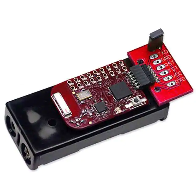
3
eZ430-RF2500 Development Tool
4
eZ430-RF2500 USB Debugging Interface 6-Pin Male Header ....................................................... 10
5
9600 bps With No Flow Control .......................................................................................... 10
6
eZ430-RF2500 Sensor Monitor
7
IAR Embedded Workbench KickStart Workspace ..................................................................... 13
8
eZ430-RF, USB Debugging Interface, Schematic ..................................................................... 16
9
eZ430-RF, USB Debugging Interface, Schematic ..................................................................... 17
10
eZ430-RF2500T, Target Board and Battery Board, Schematic ...................................................... 18
11
eZ430-RF, USB Debugger, PCB Components Layout ................................................................ 19
12
eZ430-RF, USB Debugger, PCB Layout ................................................................................ 19
13
eZ430-RF2500T, Target Board, PCB Layout ........................................................................... 19
14
Windows XP Hardware Recognition ..................................................................................... 20
15
Windows XP Hardware Recognition for MSP430 Application UART................................................ 20
16
Windows XP Found New Hardware Wizard ............................................................................ 20
17
Windows XP Hardware Wizard ........................................................................................... 21
18
Windows XP Warning...................................................................................................... 21
19
Device Manager ............................................................................................................ 22
........................................................................................
..........................................................................................
7
12
List of Tables
1
eZ430-RF2500T Target Board Pinouts ................................................................................... 7
2
Battery Board Pinouts ....................................................................................................... 8
SLAU227F – September 2007 – Revised June 2015
Submit Documentation Feedback
Copyright © 2007–2015, Texas Instruments Incorporated
List of Figures
3
�Preface
SLAU227F – September 2007 – Revised June 2015
Read This First
If You Need Assistance
Support for MSP430™ devices and the eZ430-RF2500 is provided by the TI Product Information Center
(PIC). Contact information for the PIC can be found on the TI website at www.ti.com. Additional devicespecific information can be found on the MSP430 website at www.ti.com/msp430 and www.ti.com/ez430rf.
NOTE:
IAR Embedded Workbench® KickStart is supported by Texas Instruments.
Although IAR Embedded Workbench KickStart is a product of IAR, Texas Instruments
provides support for KickStart. Therefore, please do not request support for KickStart from
IAR. Consult all provided documentation with KickStart before requesting assistance.
We Would Like to Hear from You
If you have any comments, feedback, or suggestions, let us know by contacting support@ti.com.
MSP430, Code Composer Studio, SimpliciTI are trademarks of Texas Instruments.
Embedded Workbench is a registered trademark of IAR Systems.
4
Preface
SLAU227F – September 2007 – Revised June 2015
Submit Documentation Feedback
Copyright © 2007–2015, Texas Instruments Incorporated
�User's Guide
SLAU227F – September 2007 – Revised June 2015
eZ430-RF2500 Development Tool
1
eZ430-RF2500 Overview. Wireless Made Easy.
The eZ430-RF2500 is a complete USB-based MSP430 wireless development tool providing all the
hardware and software to evaluate the MSP430F2274 microcontroller and CC2500 2.4-GHz wireless
transceiver.
The eZ430-RF2500 uses the IAR Embedded Workbench Integrated Development Environment (IDE) or
Code Composer Studio™ (CCS) IDE to write, download, and debug an application. The debugger is
unobtrusive, allowing the user to run an application at full speed with both hardware breakpoints and
single stepping available while consuming no extra hardware resources.
The eZ430-RF2500T target board is an out-of-the box wireless system that may be used with the USB
debugging interface, as a stand-alone system with or without external sensors, or may be incorporated
into an existing design.
The USB debugging interface enables the eZ430-RF2500 to remotely send and receive data from a PC
using the MSP430 Application UART.
eZ430-RF2500 features:
• USB debugging and programming interface featuring a driverless installation and application
backchannel
• 21 available development pins
• Highly-integrated ultra-low-power MSP430 MCU with 16-MHz performance
• Two general-purpose digital I/O pins connected to green and red LEDs for visual feedback
• Interruptible push button for user feedback
Figure 1. eZ430-RF2500
SLAU227F – September 2007 – Revised June 2015
Submit Documentation Feedback
Copyright © 2007–2015, Texas Instruments Incorporated
eZ430-RF2500 Development Tool
5
�Kit Contents, eZ430-RF2500
www.ti.com
Figure 2. eZ430-RF2500 Battery Board
2
Kit Contents, eZ430-RF2500
•
The hardware includes:
– Two eZ430-RF2500T target boards
– One eZ430-RF USB debugging interface
– One AAA battery pack with expansion board (batteries included)
NOTE: Visit the TI website for the latest versions of the documentation and development software
for eZ430-RF2500:
•
MSP430x2xx Family User’s Guide (SLAU144)
•
eZ430-RF2500 User’s Guide (SLAU227)
•
Code Composer Studio (CCS) Integrated Development Environment (IDE)
•
IAR Embedded Workbench KickStart IDE
•
eZ430-RF2500 Sensor Monitor (Code and Visualizer) (SLAC139)
6
eZ430-RF2500 Development Tool
SLAU227F – September 2007 – Revised June 2015
Submit Documentation Feedback
Copyright © 2007–2015, Texas Instruments Incorporated
�Developing With eZ430-RF2500T Target Board
www.ti.com
3
Developing With eZ430-RF2500T Target Board
The eZ430-RF2500 can be used as a stand-alone development tool. Additionally, the eZ430-RF2500T
target board also may be detached from the debugging interface and integrated into another design by
removing the plastic enclosure. The target board features an MSP430F2274 and most of its pins are
easily accessible. The pins are shown in Figure 3 and described in Table 1 and Table 2.
Battery Board
More development pins
(0.1-inch spacing)
Power In and Ground
Spy-Bi-Wire Interface
F2274
P3.5/UCA0RXD/UCA0SOMI
CC2500
VCC (3.6 V)
TEST/SBWTCK
eZ430-RF2500T
Target Board
RST/SBWTDIO
GND
UART
P3.4/UCA0TXD/UCA0SIMO
18 available development pins
(0.1-inch spacing)
Figure 3. eZ430-RF2500 Development Tool
Table 1. eZ430-RF2500T Target Board Pinouts
Pin
Function
Description
1
GND
Ground reference
2
VCC
Supply voltage
3
P2.0 / ACLK / A0 / OA0I0
General-purpose digital I/O pin
ACLK output
ADC10, analog input A0
4
P2.1 / TAINCLK / SMCLK / A1 / A0O
General-purpose digital I/O pin
ADC10, analog input A1
Timer_A, clock signal at INCLK
SMCLK signal output
5
P2.2 / TA0 / A2 / OA0I1
General-purpose digital I/O pin
ADC10, analog input A2
Timer_A, capture: CCI0B input/BSL receive, compare: OUT0 output
6
P2.3 / TA1 / A3 / VREF− / VeREF− / OA1I1 /
OA1O
General-purpose digital I/O pin
Timer_A, capture: CCI1B input, compare: OUT1 output
ADC10, analog input A3
Negative reference voltage output/input
7
P2.4 / TA2 / A4 / VREF+ / VeREF+ / OA1I0
General-purpose digital I/O pin
Timer_A, compare: OUT2 output
ADC10, analog input A4
Positive reference voltage output/input
8
P4.3 / TB0 / A12 / OA0O
General-purpose digital I/O pin
ADC10 analog input A12
Timer_B, capture: CCI0B input, compare: OUT0 output
9
P4.4 / TB1 / A13 / OA1O
General-purpose digital I/O pin
ADC10 analog input A13
Timer_B, capture: CCI1B input, compare: OUT1 output
10
P4.5 / TB2 / A14 / OA0I3
General-purpose digital I/O pin
ADC10 analog input A14
Timer_B, compare: OUT2 output
11
P4.6 / TBOUTH / A15 / OA1I3
General-purpose digital I/O pin
ADC10 analog input A15
Timer_B, switch all TB0 to TB3 outputs to high impedance
12
GND
Ground reference
13
P2.6 / XIN (GDO0)
General-purpose digital I/O pin
Input terminal of crystal oscillator
14
P2.7 / XOUT (GDO2)
General-purpose digital I/O pin
Output terminal of crystal oscillator
SLAU227F – September 2007 – Revised June 2015
Submit Documentation Feedback
Copyright © 2007–2015, Texas Instruments Incorporated
eZ430-RF2500 Development Tool
7
�Developing With eZ430-RF2500T Target Board
www.ti.com
Table 1. eZ430-RF2500T Target Board Pinouts (continued)
Pin
Function
Description
15
P3.2 / UCB0SOMI / UCB0SCL
General-purpose digital I/O pin
USCI_B0 slave out/master in when in SPI mode
SCL I2C clock in I2C mode
16
P3.3 / UCB0CLK / UCA0STE
General-purpose digital I/O pin
USCI_B0 clock input/output
USCI_A0 slave transmit enable
17
P3.0 / UCB0STE / UCA0CLK / A5
General-purpose digital I/O pin
USCI_B0 slave transmit enable
USCI_A0 clock input/output
ADC10, analog input A5
18
P3.1 / UCB0SIMO / UCB0SDA
General-purpose digital I/O pin
USCI_B0 slave in/master out in SPI mode
SDA I2C data in I2C mode
Table 2. Battery Board Pinouts
Pin
8
Function
Description
1
P3.4 / UCA0TXD / UCA0SIMO
General-purpose digital I/O pin
USCI_A0 transmit data output in UART mode (UART communication from 2274 to PC)
Slave in/master out in SPI mode
2
GND
Ground reference
3
RST / SBWTDIO
Reset or nonmaskable interrupt input
Spy-Bi-Wire test data input/output during programming and test
4
TEST / SBWTCK
Selects test mode for JTAG pins on Port1. The device protection fuse is connected to
TEST. Spy-Bi-Wire test clock input during programming and test
5
VCC (3.6V)
Supply voltage
6
P3.5 / UCA0RXD / UCA0SOMI
General-purpose digital I/O pin
USCI_A0 receive data input in UART mode (UART communication from 2274 to PC)
Slave out/master in when in SPI mode
eZ430-RF2500 Development Tool
SLAU227F – September 2007 – Revised June 2015
Submit Documentation Feedback
Copyright © 2007–2015, Texas Instruments Incorporated
�Specifications
www.ti.com
4
Specifications
MSP430F2274
• 16-MIPS performance
• 200-ksps 10-bit SAR ADC
• Two built-in operational amplifiers
• Watchdog timer, 16-bit Timer_A3 and Timer_B3
• USCI module supports UART/LIN, (2) SPI, I2C, or IrDA
• Five low-power modes that draw as little as 700 nA in standby
PARAMETER
MIN
TYP
MAX UNIT
OPERATING CONDITIONS
Operating supply voltage
1.8
3.6
V
Operating free-air temperature range
-40
85
°C
CURRENT CONSUMPTION
Active mode at 1 MHz, 2.2 V
270
390
µA
Standby mode
0.7
1.4
µA
Off mode with RAM retention
0.1
0.5
µA
16
MHz
OPERATING FREQUENCY
VCC ≥ 3.3 V
CC2500
• 2.4-GHz radio-frequency (RF) transceiver
• Programmable data rate up to 500 kbps
• Low current consumption
PARAMETER
TEST CONDITIONS
MIN
TYP
MAX UNIT
OPERATING CONDITIONS
Operating supply voltage
1.8
3.6
V
CURRENT CONSUMPTION
RX input signal at the sensitivity limit, 250 kbps
RX input signal 30 dB above the sensitivity limit, 250 kbps
Optimized current
16.6
Optimized sensitivity
18.8
Optimized current
13.3
Optimized sensitivity
15.7
mA
mA
Current consumption TX (0 dBm)
21.2
mA
Current consumption TX (-12 dBm)
11.1
mA
RF CHARACTERISTICS
Frequency range
2400
2483.5
MHz
Data rate (programmable)
1.2
500
kbps
Output power (programmable)
-30
0
dBm
Optimized current, 2-FSK, 230-kHz
RX filter bandwidth, 1% PER
Sensitivity, 10 kbps
Optimized sensitivity
Sensitivity, 250 kbps
-99
-101
Optimized current, 500-kHz RX
filter bandwidth, 1% PER
-87
Optimized sensitivity
-89
SLAU227F – September 2007 – Revised June 2015
Submit Documentation Feedback
Copyright © 2007–2015, Texas Instruments Incorporated
eZ430-RF2500 Development Tool
dBm
9
�Supported Devices
5
www.ti.com
Supported Devices
The eZ430-RF USB debugging interface may be used as a standard Flash Emulation Tool through its
Spy-Bi-Wire interface. The eZ430-RF USB debugging interface supports the following MSP430 families:
• MSP430F20xx
• MSP430F22xx
The connector on the USB debugging interface is backward compatible with the eZ430-F2013 and T2012
target boards.
TX
3.6 V
TEST/SBWTCK
RST/SBWTDIO
Supports eZ430-F2013
and T2012 target boards
GND
RX
Figure 4. eZ430-RF2500 USB Debugging Interface 6-Pin Male Header
6
MSP430 Application UART
The eZ430-RF USB debugging interface features a back channel MSP430 Application UART that may be
used independently of a debug session. This allows the user to transfer serial data to a terminal window at
a fixed rate of 9600 bps with no flow control. See Figure 5 for typical settings.
Figure 5. 9600 bps With No Flow Control
Check the Device Manager for COM port assignment of the MSP430 Application UART. For more details,
see Section 14.
10
eZ430-RF2500 Development Tool
SLAU227F – September 2007 – Revised June 2015
Submit Documentation Feedback
Copyright © 2007–2015, Texas Instruments Incorporated
�Software Installation
www.ti.com
7
Software Installation
Two different development software tools for the MSP430 are available from TI: IAR Embedded
Workbench KickStart and Code Composer Studio (CCS). The term "KickStart" refers to the limited version
of Embedded Workbench that allows up to 4KB of C-code compilation.
7.1
Installing the IDE
1. Download the IDE of your choice:
IAR Embedded Workbench KickStart: http://www.ti.com/tool/IAR-KICKSTART
Code Composer Studio: http://www.ti.com/tool/ccstudio
2. Respond to the prompts to install the software. The installation procedure installs the IDE and TI files.
7.2
Installing the Sensor Monitor Visualizer Application
1. Download the latest version of eZ430-RF2500 Sensor Monitor (Code and Visualizer):
http://www.ti.com/lit/zip/slac139
2. Run Sensor Monitor Installer.exe.
3. Choose the installation path for the software.
4. Open the eZ430-RF2500 Sensor Monitor using the shortcut that is installed on the desktop.
8
Hardware Installation
1. Insert the eZ430-RF into USB port. The debugging interface automatically installs itself.
2. When prompted for the software for the MSP430 Application UART, allow Windows to Install the
software automatically. This is only possible if either IAR KickStart R4.64 (or higher) or the Sensor
Monitor Visualizer has already been installed. For more information, see Section 14.
9
SimpliciTI™ Network Protocol
The SimpliciTI™ network protocol is a proprietary, low-power radio-frequency (RF) protocol targeting
simple, small RF networks (