User's Guide
SLAU176E – February 2006 – Revised March 2019
eZ430-F2013 Development Tool
This document describes the eZ430-F2013, which is a complete MSP430 development tool in a
convenient USB stick form factor. This tool provides all of the hardware and software that is required to
evaluate the MSP430F2013 microcontroller (MCU) and complete an entire project.
1
2
3
4
5
6
7
8
9
10
Contents
eZ430-F2013 Overview .....................................................................................................
Kit Contents, eZ430-F2013 .................................................................................................
Software Installation .........................................................................................................
Hardware Installation ........................................................................................................
Flashing the LED Demo Using IAR Embedded Workbench IDE ......................................................
Flashing the LED Demo Using Code Composer Studio IDE ..........................................................
Using the MSP430F2013 Target Board and Debugging Interface Independently ..................................
Where To Go For More Information .......................................................................................
Frequently Asked Questions ...............................................................................................
Schematics ...................................................................................................................
2
2
3
3
3
4
4
4
5
6
Trademarks
MSP430, Code Composer Studio are trademarks of Texas Instruments.
IAR Embedded Workbench is a registered trademark of IAR Systems.
Windows is a registered trademark of Microsoft Corporation.
SLAU176E – February 2006 – Revised March 2019
Submit Documentation Feedback
Copyright © 2006–2019, Texas Instruments Incorporated
eZ430-F2013 Development Tool
1
�eZ430-F2013 Overview
1
www.ti.com
eZ430-F2013 Overview
The eZ430-F2013 is a complete development tool for the MSP430™ MCU and provides all of the
hardware and software that is required to evaluate the MSP430F2013 and complete an entire project in a
convenient USB stick form factor. The eZ430-F2013 uses the IAR Embedded Workbench IDE or Code
Composer Studio IDE to provide full emulation with the option of designing a stand-alone system or
detaching the removable target board to integrate into an existing design. The USB port provides power to
operate the ultra-low-power MSP430 so no external power supply is required.
All 14 pins on the MSP430F2013 are accessible on the MSP-EZ430D target board for easy debugging
and interfacing with peripherals. Additionally, one of the digital I/O pins is connected to an LED for visual
feedback. The MSP430F2013 includes 16-MIPS performance, a 16-bit sigma delta analog-to-digital
converter, a 16-bit timer, watchdog timer, brownout detector, a USI module supporting SPI and I2C, and
five low-power modes drawing as little as 0.5 µA standby.
Figure 1. eZ430-F2013 Development Tool
2
Kit Contents, eZ430-F2013
•
•
2
One eZ430-F2013. The hardware is housed in a plastic enclosure that can be opened to separate the
MSP-EZ430D target board from the MSP-EZ430U debugging interface.
One MSP430 Development Tool CD-ROM that contains several documents including the following
related to the eZ430-F2013:
– MSP430x2xx Family User's Guide
– eZ430-F2013 Development Tool user's guide (this document)
– IAR Embedded Workbench® KickStart Version
– Code Composer Studio™ IDE
eZ430-F2013 Development Tool
SLAU176E – February 2006 – Revised March 2019
Submit Documentation Feedback
Copyright © 2006–2019, Texas Instruments Incorporated
�Software Installation
www.ti.com
3
Software Installation
The latest versions of these IDEs are available from the MSP430 web site at www.ti.com/msp430.
1. Insert the MSP430 CD-ROM into your computer. It should start automatically, and the MSP430 start
page will then be displayed. You can also use a browser to open "index.htm" that is located in the root
directory of the MSP430 CD-ROM. The eZ430-F2013 is compatible with Windows® operating systems.
2. Select Software → IAR Workbench Kickstart or Software → Code Composer Studio and follow the
instructions.
3. Respond to the prompts to install the software. The installation procedure installs IAR and TI files.
4. Finish the installation.
4
Hardware Installation
1. Install you development environment of preference, either IAR Embedded Workbench IDE or Code
Composer Studio IDE.
2. Drivers are installed automatically during installation of the IDE.
3. Plug the eZ430 emulator into a USB port on the PC.
5
Flashing the LED Demo Using IAR Embedded Workbench IDE
This section describes how to set up a project for the eZ430-F2013 and download the application to the
MSP430F2013. The sample program will blink the LED on the MSP-EZ430D target board.
Start the Workbench (click Start → Programs → IAR Systems → IAR Embedded Workbench Kickstart for
MSP430 V3 → IAR Embedded Workbench).
1. Click File → Open Workspace to open the file at C:\Program Files\IAR Systems\Embedded Workbench
4.0\430\ FET_examples\Flashing the LED.eww. The workspace window opens.
2. Select the msp430x2xx (C – SpyBiWire) tab at the bottom of the workspace window that corresponds
to the eZ430-F2013.
3. Set the correct device by clicking Projects → Options → General Options → Target and select the
MSP430F2013 from the device list.
4. In the Options windows, go to FET Debugger → Setup → Connection and select TI USB FET to use
the USB interface.
5. Click Project → Rebuild All to build and link the source code. You can view the source code by doubleclicking on the project, and then double-clicking on the displayed source file.
6. Click Project → Download & Debug to start the C-SPY debugger. C-SPY will erase the device flash
and then download the application object file to the device flash.
7. Click Debug → Go to start the application. The LED should illuminate.
8. Click Debug → Stop Debugging to stop debugging, to exit C-SPY and to return to the Workbench.
9. Click File → Exit to exit the Workbench.
Congratulations, you've just built and tested your first MSP430 application.
SLAU176E – February 2006 – Revised March 2019
Submit Documentation Feedback
Copyright © 2006–2019, Texas Instruments Incorporated
eZ430-F2013 Development Tool
3
�Flashing the LED Demo Using Code Composer Studio IDE
6
www.ti.com
Flashing the LED Demo Using Code Composer Studio IDE
This section describes how to setup a project for the eZ430-F2013 and download the application to the
MSP430F2013. The sample program will blink the LED on the MSP-EZ430D target board.
Start CCS (Start → Programs → Texas Instruments → Code Composer Studio v4 → Code Composer
Studio v4).
1. Project → Import Existing CCS/CCE Eclipse Project
2. Select Root Directory: C:\Program Files\Texas Instruments\CCSv4\msp430\examples\example
projects\msp430x2xx C Example
3. Click Finish.
4. Use Target → Debug Active Target to begin the debug session.
5. If there is a device mismatch, click ignore.
6. Use Target → Run to start the application.
7. Observe blinking LED.
8. Use Target → Terminate All to exit debug session.
9. Use File → Exit to exit the IDE.
Congratulations, you've just built and tested your first MSP430 application.
7
Using the MSP430F2013 Target Board and Debugging Interface Independently
The eZ430-F2013 may be used as a stand-alone development board. Additionally, the MSP-EZ430D
target board may also be detached from the debugging interface and integrated into another design.
The plastic enclosure can be removed to expose the MSP-EZ430U debugging interface and the MSPEZ430D target board. The MSP-EZ430D target board is disconnected from the debugging interface by
gently pulling the two boards apart.
The target board can be used in a stand-alone design by interfacing to the 14-pins of the MSP430F2013.
Holes in the MSP-EZ430D target board provide direct access to each pin of the MSP430F2013. Please
refer to the MSP430F2013 Data Sheet for descriptions of each pin's function.
The MSP-EZ430U debugging interface may also be used as a standard Flash Emulation Tool for all
devices in the MSP430F20xx family of microcontrollers. Target boards using other supported
MSP430F20xx devices may be designed and flashed using the MSP-EZ430U debugging interface.
8
Where To Go For More Information
The primary sources of MSP430 information are the device-specific data sheets and user's guides. The
most up to date versions of the user's guide documents available at the time of production have been
provided on the CD-ROM included with this tool. The most current information is found at
www.ti.com/msp430. Information specific to the eZ430-F2013 development tool can be found at
www.ti.com/ez430.
MSP430 device user's guides and the FET user's guide may be accessed from the main page on the CDROM under the user's guides section. The FET user's guide includes detailed information on setting up a
project for the MSP430 using either IDE.
Documents that describe the IAR tools (Workbench/C-SPY, the assembler, the C compiler, the linker, and
the librarian) are located in common\doc and 430\doc. 430\doc\readme_start.htm provides a convenient
starting point for navigating the IAR documentation.
Documents that describe the Code Composer Studio IDE are located in the "documentation" folder.
4
eZ430-F2013 Development Tool
SLAU176E – February 2006 – Revised March 2019
Submit Documentation Feedback
Copyright © 2006–2019, Texas Instruments Incorporated
�Frequently Asked Questions
www.ti.com
9
Frequently Asked Questions
1. What devices can be programmed with the MSP-EZ430U debugging interface?
MSP430F200x, MSP430F201x, MSP430G2x01, MSP430G2x11, MSP430G2x21, and MSP430G2x31
2. Does the eZ430-F2013 support fuse blow?
The MSP-EZ430U debugging interface lacks the JTAG security fuse blow capability. To ensure
firmware security on devices going to production, the USB Flash Emulation Tool or the Gang
Programmer, which include the fuse blow feature, are recommended.
3. What is the voltage supplied to the MSP-EZ430D target board from the debugging interface?
The MSP-EZ430U debugging interface supplies a regulated 3.6 V to the MSP-EZ430D target board.
4. Can other programming tools interface to the MSP-EZ430D target board?
The MSP-EZ430D target board works with any programming tool that supports the 2-wire Spy-Bi-Wire
interface. Both the MSP430 USB FET and the Gang Programmer support these devices.
5. What versions of IDEs are supported?
The eZ430-F2013 is supported by IAR Embedded Workbench IDE 3.40A and IAR Embedded
Workbench IDE (Kickstart version) FET_R449 or higher and Code Composer Studio IDE v3 or higher.
6. What are the part numbers for the connectors between the MSP-EZ430U emulator and the MSPEZ430D target board?
Header: Mill-Max 850-10-004-20-001000 (Digi-Key part number ED8650-ND)
Socket: Mill-Max 851-93-004-20-001000 (Digi-Key part number ED8850-ND)
Mill-Max: http://www.mill-max.com
7. Why does the debugger fail to start (IAR error: Failed to initialize device)?
First, check in the Device Manager that the COM port assigned to the eZ430 does not conflict with a
port already in use. You can disable the conflicting port or assign a new COM port to the device.
Check all devices that use a serial port; even devices that do not show up in the Device Manager.
Second, check if capacitors C6 or C9 on the MSP-EZ430U debugging interface are populated. These
capacitors may have been unintentionally removed while opening the enclosure.
8. What is the difference between the 4-pin and 6-pin headers?
The 4-pin and 6-pin headers are identical from a JTAG perspective. The 6-pin header has two
additional pins (pin 1 and pin 6) that can perform UART communication. See the schematics in
Section 10 for details.
SLAU176E – February 2006 – Revised March 2019
Submit Documentation Feedback
Copyright © 2006–2019, Texas Instruments Incorporated
eZ430-F2013 Development Tool
5
�Schematics
10
www.ti.com
Schematics
Figure 2. MSP-eZ430U Schematic (1 of 2)
6
eZ430-F2013 Development Tool
SLAU176E – February 2006 – Revised March 2019
Submit Documentation Feedback
Copyright © 2006–2019, Texas Instruments Incorporated
�Schematics
www.ti.com
Figure 3. MSP-eZ430U Schematic (2 of 2)
SLAU176E – February 2006 – Revised March 2019
Submit Documentation Feedback
Copyright © 2006–2019, Texas Instruments Incorporated
eZ430-F2013 Development Tool
7
�Schematics
www.ti.com
Figure 4. MSP-EZ430D Schematic
8
eZ430-F2013 Development Tool
SLAU176E – February 2006 – Revised March 2019
Submit Documentation Feedback
Copyright © 2006–2019, Texas Instruments Incorporated
�Schematics
www.ti.com
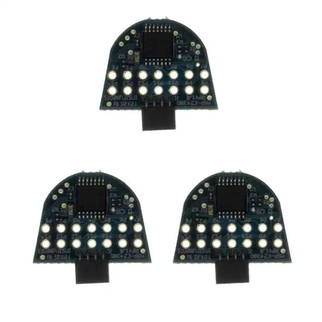
Figure 5. eZ430-F2013 PCB
SLAU176E – February 2006 – Revised March 2019
Submit Documentation Feedback
Copyright © 2006–2019, Texas Instruments Incorporated
eZ430-F2013 Development Tool
9
�Revision History
www.ti.com
Revision History
NOTE: Page numbers for previous revisions may differ from page numbers in the current version.
Changes from June 15, 2010 to March 19, 2019 ............................................................................................................. Page
•
•
•
10
Moved Section 1, eZ430-F2013 Overview ............................................................................................. 2
Editorial and format changes and updates to links throughout document ......................................................... 2
Removed former Preface................................................................................................................. 2
Revision History
SLAU176E – February 2006 – Revised March 2019
Submit Documentation Feedback
Copyright © 2006–2019, Texas Instruments Incorporated
�IMPORTANT NOTICE AND DISCLAIMER
TI PROVIDES TECHNICAL AND RELIABILITY DATA (INCLUDING DATA SHEETS), DESIGN RESOURCES (INCLUDING REFERENCE
DESIGNS), APPLICATION OR OTHER DESIGN ADVICE, WEB TOOLS, SAFETY INFORMATION, AND OTHER RESOURCES “AS IS”
AND WITH ALL FAULTS, AND DISCLAIMS ALL WARRANTIES, EXPRESS AND IMPLIED, INCLUDING WITHOUT LIMITATION ANY
IMPLIED WARRANTIES OF MERCHANTABILITY, FITNESS FOR A PARTICULAR PURPOSE OR NON-INFRINGEMENT OF THIRD
PARTY INTELLECTUAL PROPERTY RIGHTS.
These resources are intended for skilled developers designing with TI products. You are solely responsible for (1) selecting the appropriate
TI products for your application, (2) designing, validating and testing your application, and (3) ensuring your application meets applicable
standards, and any other safety, security, regulatory or other requirements.
These resources are subject to change without notice. TI grants you permission to use these resources only for development of an
application that uses the TI products described in the resource. Other reproduction and display of these resources is prohibited. No license
is granted to any other TI intellectual property right or to any third party intellectual property right. TI disclaims responsibility for, and you
will fully indemnify TI and its representatives against, any claims, damages, costs, losses, and liabilities arising out of your use of these
resources.
TI’s products are provided subject to TI’s Terms of Sale or other applicable terms available either on ti.com or provided in conjunction with
such TI products. TI’s provision of these resources does not expand or otherwise alter TI’s applicable warranties or warranty disclaimers for
TI products.
TI objects to and rejects any additional or different terms you may have proposed. IMPORTANT NOTICE
Mailing Address: Texas Instruments, Post Office Box 655303, Dallas, Texas 75265
Copyright © 2022, Texas Instruments Incorporated
�