Product
Folder
Order
Now
Support &
Community
Tools &
Software
Technical
Documents
FPC202
SNLS565 – DECEMBER 2017
FPC202 Dual Port Controller With Expanded I/Os
1 Features
2 Applications
•
•
•
1
•
•
•
•
•
•
•
•
•
•
•
•
Supports Control Signal Management and I2C
Aggregation Across Two Ports
Four LED Drivers and 12 General-Purpose I/Os
Per Port
General-Purpose Outputs Can be Used to Drive
>4 LEDs Per Port
Combine Multiple FPC202s to Control 28 Total
Ports Through a Single Host Interface
Eliminates Need for Discrete I2C Multiplexers,
LED Drivers, and High-Pin-Count FPGA/CPLD
Control Devices
Reduces PCB Routing Complexity by Handling All
Low-Speed Control Signals Close to the Port
Selectable I2C (Up to 1 MHz) or SPI (Up to 10
MHz) Host Control Interface
Automatic Pre-Fetching of Critical, User-Specified
Data from the Modules
Broadcast Mode Allows Writes to All Ports
Simultaneously Across All FPC202 Controllers
Advanced LED Features for Port Status
Indication, Including Programmable Blinking and
Dimming
Customizable Interrupt Events
Separate Host-Side I/O Voltage: 1.8 V to 3.3 V
Small QFN Package Enabling Placement on
Bottom Side of PCB Underneath Ports
•
•
•
ToR/Aggregation/Core Switch and Router
Wireless Infrastructure Base Band Unit and
Remote Radio Unit
Network Interface Card (NIC) and Host Bus
Adapter (HBA)
Storage Cards and Storage Racks
SFP, QSFP, QSFP-DD, OSFP, Mini-SAS HD Port
Management
3 Description
The FPC202 dual port controller serves as a lowspeed signal aggregator for common port types such
as SFP, QSFP, Mini-SAS HD, and others. The
FPC202 aggregates all low-speed control and I2C
signals across two ports and presents a single easyto-use management interface to the host (I2C or SPI).
Multiple FPC202s can be used in high-port-count
applications with one common control interface to the
host.
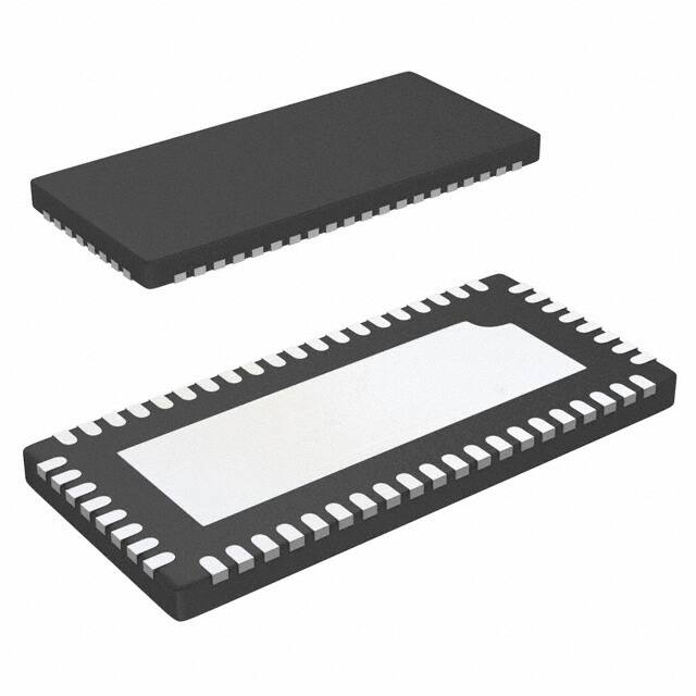
Device Information(1)
PART NUMBER
FPC202
PACKAGE
QFN (56)
BODY SIZE (NOM)
5.00 mm x 11.00 mm
(1) For all available packages, see the orderable addendum at
the end of the data sheet.
Simplified Block Diagram
INT
SCL
SDA
HOST
CONTROLLER
FPC202 DUAL PORT CONTROLLER WITH EXPANDED I/Os
PORT 0
PORT 1
FPC202 DUAL PORT CONTROLLER WITH EXPANDED I/Os
PORT 0
PORT 1
I2C,
STATUS,
CONTROL
I2C,
STATUS,
CONTROL
SFP,
QSFP,
QSFP-DD,
OSFP
SFP,
QSFP,
QSFP-DD,
OSFP
SFP,
QSFP,
QSFP-DD,
OSFP
SFP,
QSFP,
QSFP-DD,
OSFP
PORT 0
PORT 1
PORT 2
PORT 3
Copyright © 2017, Texas Instruments Incorporated
1
An IMPORTANT NOTICE at the end of this data sheet addresses availability, warranty, changes, use in safety-critical applications,
intellectual property matters and other important disclaimers. PRODUCTION DATA.
�FPC202
SNLS565 – DECEMBER 2017
www.ti.com
Table of Contents
1
2
3
4
5
6
7
Features ..................................................................
Applications ...........................................................
Description .............................................................
Revision History.....................................................
Description Continued ..........................................
Device Comparison Table.....................................
Device and Documentation Support....................
7.1
7.2
7.3
7.4
7.5
7.6
1
1
1
2
3
3
4
8
Documentation Support ...........................................
Receiving Notification of Documentation Updates....
Community Resources..............................................
Trademarks ...............................................................
Electrostatic Discharge Caution ................................
Glossary ....................................................................
4
4
4
4
4
4
Mechanical, Packaging, and Orderable
Information ............................................................. 4
4 Revision History
2
DATE
REVISION
NOTES
December 2017
*
Initial release.
Submit Documentation Feedback
Copyright © 2017, Texas Instruments Incorporated
Product Folder Links: FPC202
�FPC202
www.ti.com
SNLS565 – DECEMBER 2017
5 Description Continued
The FPC202 is designed to allow placement on the bottom side of the PCB, underneath the press fit connector,
to simplify routing. This localized control of the ports’ low-speed signals cuts system bill of materials (BOM) cost
by enabling the use of smaller I/O count control devices (FPGAs, CPLDs, MCUs) and by reducing routing layer
congestion.
The FPC202 is compatible with standard SFF-8431, SFF-8436, and SFF-8449 low-speed management
interfaces, including a dedicated 100/400-kHz I2C interface to each port. Additional general-purpose pins are
available to perform functions such as driving port status LEDs or controlling power switches. The LED drivers
have convenience features such as programmable blinking and dimming. The interface to the host controller can
operate on a separate supply voltage between 1.8 V and 3.3 V to support low-voltage I/Os.
For each port, the FPC202 has a total of four LED drivers, 12 general-purpose I/Os, and two downstream I2C
busses. This expanded set of I/Os allows for control of additional components and features within a system. The
general-purpose outputs can be used to drive additional LEDs if more than four are required per port.
The FPC202 can pre-fetch data from user-specified registers in each module, making the data readily accessible
to the host through a fast I2C (up to 1 MHz) or SPI (up to 10 MHz) interface. In addition, the FPC202 can trigger
an interrupt to the host whenever critical, user-configurable events occur associated with any of the ports under
its control. This eliminates the need to continuously poll the modules.
6 Device Comparison Table
PART NUMBER
PORTS
LED DRIVERS PER PORT
GPIOs PER PORT
ACCESSIBLE DOWNSTREAM
ADDRESSES
FPC202
2
4
12
All valid I2C addresses
FPC402
4
2
6
All valid I2C addresses
FPC401
4
2
6
MSA addresses: 0xA0, 0xA2
Submit Documentation Feedback
Copyright © 2017, Texas Instruments Incorporated
Product Folder Links: FPC202
3
�FPC202
SNLS565 – DECEMBER 2017
www.ti.com
7 Device and Documentation Support
7.1 Documentation Support
7.1.1 Related Documentation
For related documentation, see the following:
• FPC202 Programmer's Guide (SNLU229)
• FPC401 Evaluation Module (EVM) User's Guide (SNLU222)
Click here to request access to these documents in the FPC202 MySecure folder.
7.2 Receiving Notification of Documentation Updates
To receive notification of documentation updates, navigate to the device product folder on ti.com. In the upper
right corner, click on Alert me to register and receive a weekly digest of any product information that has
changed. For change details, review the revision history included in any revised document.
7.3 Community Resources
The following links connect to TI community resources. Linked contents are provided "AS IS" by the respective
contributors. They do not constitute TI specifications and do not necessarily reflect TI's views; see TI's Terms of
Use.
TI E2E™ Online Community TI's Engineer-to-Engineer (E2E) Community. Created to foster collaboration
among engineers. At e2e.ti.com, you can ask questions, share knowledge, explore ideas and help
solve problems with fellow engineers.
Design Support TI's Design Support Quickly find helpful E2E forums along with design support tools and
contact information for technical support.
7.4 Trademarks
E2E is a trademark of Texas Instruments.
All other trademarks are the property of their respective owners.
7.5 Electrostatic Discharge Caution
This integrated circuit can be damaged by ESD. Texas Instruments recommends that all integrated circuits be handled with
appropriate precautions. Failure to observe proper handling and installation procedures can cause damage.
ESD damage can range from subtle performance degradation to complete device failure. Precision integrated circuits may be more
susceptible to damage because very small parametric changes could cause the device not to meet its published specifications.
7.6 Glossary
SLYZ022 — TI Glossary.
This glossary lists and explains terms, acronyms, and definitions.
8 Mechanical, Packaging, and Orderable Information
The following pages include mechanical, packaging, and orderable information. This information is the most
current data available for the designated devices. This data is subject to change without notice and revision of
this document. For browser-based versions of this data sheet, refer to the left-hand navigation.
4
Submit Documentation Feedback
Copyright © 2017, Texas Instruments Incorporated
Product Folder Links: FPC202
�PACKAGE OPTION ADDENDUM
www.ti.com
10-Dec-2020
PACKAGING INFORMATION
Orderable Device
Status
(1)
Package Type Package Pins Package
Drawing
Qty
Eco Plan
(2)
Lead finish/
Ball material
MSL Peak Temp
Op Temp (°C)
Device Marking
(3)
(4/5)
(6)
FPC202RHUR
ACTIVE
WQFN
RHU
56
2000
RoHS & Green
SN
Level-2-260C-1 YEAR
-40 to 85
FPC2
FPC202RHUT
ACTIVE
WQFN
RHU
56
250
RoHS & Green
SN
Level-2-260C-1 YEAR
-40 to 85
FPC2
(1)
The marketing status values are defined as follows:
ACTIVE: Product device recommended for new designs.
LIFEBUY: TI has announced that the device will be discontinued, and a lifetime-buy period is in effect.
NRND: Not recommended for new designs. Device is in production to support existing customers, but TI does not recommend using this part in a new design.
PREVIEW: Device has been announced but is not in production. Samples may or may not be available.
OBSOLETE: TI has discontinued the production of the device.
(2)
RoHS: TI defines "RoHS" to mean semiconductor products that are compliant with the current EU RoHS requirements for all 10 RoHS substances, including the requirement that RoHS substance
do not exceed 0.1% by weight in homogeneous materials. Where designed to be soldered at high temperatures, "RoHS" products are suitable for use in specified lead-free processes. TI may
reference these types of products as "Pb-Free".
RoHS Exempt: TI defines "RoHS Exempt" to mean products that contain lead but are compliant with EU RoHS pursuant to a specific EU RoHS exemption.
Green: TI defines "Green" to mean the content of Chlorine (Cl) and Bromine (Br) based flame retardants meet JS709B low halogen requirements of