User's Guide
SBOU125 – June 2012
INA223EVM User’s Guide and Software Tutorial
INA223EVM
This user's guide describes the characteristics, operation, and use of the INA223EVM evaluation board. It
discusses how to set up and configure the software and hardware, and reviews various aspects of the
program operation. This user's guide also includes information regarding operating procedures and
input/output connections, an electrical schematic, printed circuit board (PCB) layout drawings, and a parts
list for the EVM.
Throughout this document, the terms evaluation board, evaluation module, and EVM are synonymous with
the INA223EVM.
Microsoft, Windows are registered trademarks of Microsoft Corporation.
SPI is a trademark of Motorola Inc,.
I2C is a trademark of NXP Semiconductors.
SBOU125 – June 2012
Submit Documentation Feedback
INA223EVM User’s Guide and Software Tutorial
Copyright © 2012, Texas Instruments Incorporated
1
�www.ti.com
INA223EVM (continued)
1
2
3
4
5
6
Contents
Overview ..................................................................................................................... 3
INA223EVM Hardware Setup ............................................................................................. 4
INA223EVM Hardware Overview ......................................................................................... 7
INA223EVM Software Setup ............................................................................................. 12
INA223EVM Software Overview ......................................................................................... 14
INA223EVM Documentation ............................................................................................. 22
List of Figures
1
Hardware Included with INA223EVM Kit................................................................................. 3
2
Hardware Setup ............................................................................................................. 4
3
INA223 Test Board Block Diagram ....................................................................................... 5
4
SM-USB-DIG Platform Block Diagram ................................................................................... 6
5
Typical Hardware Test Connections on the INA223EVM.............................................................. 7
6
Connecting the USB Cable to the SM-USB-DIG Platform............................................................. 8
7
Confirmation of SM-USB-DIG Platform Driver Installation............................................................. 8
8
INA223EVM Default Jumpers ............................................................................................. 9
9
Typical Filter Setup ........................................................................................................ 11
10
INA223 Shunt Configurations ............................................................................................ 11
11
Software Install Window .................................................................................................. 12
12
Software License Agreement ............................................................................................ 13
13
Software Install Progress ................................................................................................. 13
14
INA223EVM Software Interface
15
16
17
18
19
20
21
22
23
24
.........................................................................................
Communication Error with SM-USB-DIG Platform ....................................................................
Setting the A0 Address ...................................................................................................
Configuring the Output Mode ............................................................................................
Configuring the Bus Voltage Gain .......................................................................................
Configuring the Current Shunt Voltage Gain ..........................................................................
Register Table .............................................................................................................
Auto-Write, Power, and Voltage Controls ..............................................................................
Example Hardware Calculator ...........................................................................................
INA223EVM Board Schematic ...........................................................................................
INA223EVM PCB Component Layout ..................................................................................
14
14
15
16
18
18
19
20
21
23
24
List of Tables
2
1
Related Documentation .................................................................................................... 4
2
INA223EVM H1 Pin Connections ......................................................................................... 5
3
INA223 Test Board Jumper Functions ................................................................................... 9
4
INA223 I2C Address Configuration ...................................................................................... 15
5
Power Gain Values ........................................................................................................ 17
6
Bill of Materials
............................................................................................................
INA223EVM User’s Guide and Software Tutorial
Copyright © 2012, Texas Instruments Incorporated
22
SBOU125 – June 2012
Submit Documentation Feedback
�Overview
www.ti.com
1
Overview
The INA223 is a voltage output device that monitors current, bus voltage, and power of a supply line by
sensing a voltage drop across a shunt. The INA223EVM is a platform for evaluating the performance of
the INA223 under various signal, shunt, and supply conditions. This document gives a general overview of
the INA223EVM, and provides a general description of the features and functions to be considered while
using this evaluation module.
1.1
INA223EVM Kit Contents
The INA223EVM kit includes the following items:
• (1) INA223 PCB evaluation board
• (1) SM-USB-DIG Platform PCB
• (1) USB extender cable
• (1) SM-USB-DIG connector ribbon cable
• (1) User’s guide CD-ROM
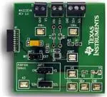
Figure 1 shows all of the included hardware. Contact the Texas Instruments Product Information Center
nearest you if any component is missing. It is highly recommended that you check the TI web site at
http://www.ti.com to verify that you have the latest versions of the related software.
USB Extender Cable
SM-USB-DIG
Connector
Ribbon Cable
INA223EVM
Board
SM-USB-DIG
Figure 1. Hardware Included with INA223EVM Kit
SBOU125 – June 2012
Submit Documentation Feedback
INA223EVM User’s Guide and Software Tutorial
Copyright © 2012, Texas Instruments Incorporated
3
�INA223EVM Hardware Setup
1.2
www.ti.com
Related Documentation
The following document provides information regarding Texas Instruments integrated circuits used in the
assembly of the INA223EVM. This user's guide is available from the TI web site under literature number
SBOU125 . Any letter appended to the literature number corresponds to the document revision that is
current at the time of the writing of this document. Newer revisions may be available from the TI web site
at http://www.ti.com, or call the Texas Instruments Literature Response Center at (800) 477-8924 or the
Product Information Center at (972) 644-5580. When ordering, identify the document by both title and
literature number.
Table 1. Related Documentation
Document
2
Literature Number
INA223 Product Data Sheet
SBOS528
SM-USB-DIG Platform User’s Guide
SBOU098
INA223EVM Hardware Setup
This section discusses the overall system setup for the INA223EVM. A PC runs software that
communicates with the SM-USB-DIG Platform. This platform generates the analog and digital signals
used to communicate with the INA223 board. Connectors on the INA223 allow the user to connect to the
system under test conditions where the power, current, and voltage are monitored.
Analog Supply
PC
Power Supply
USB SM-DIG
INA223EVM
Shunt
Load
GND
Figure 2. Hardware Setup
4
INA223EVM User’s Guide and Software Tutorial
Copyright © 2012, Texas Instruments Incorporated
SBOU125 – June 2012
Submit Documentation Feedback
�INA223EVM Hardware Setup
www.ti.com
2.1
Theory of Operation for INA223 Hardware
A block diagram of the INA223 test-board hardware setup is shown in Figure 3. The PCB provides
connections to the I2C™ and general-purpose inputs and outputs (GPIO) on the SM-USB-DIG Platform
board. It also provides connection points for external connections to the shunt voltage.
Shunt
Terminal
10-Pin SM-DIG Connector
T2
Supply Voltage
2
A0
Vs
Vdut
H1
INA223
JMP1/JMP2
I2C Addr
Jumper
I2C Interface
Figure 3. INA223 Test Board Block Diagram
2.2
Signal Definitions of H1 (10-Pin Male Connector Socket)
Table 2 shows the pinout for the 10-pin connector socket used to communicate between the INA223EVM
and the SM-USB-DIG. It should be noted that to issue commands to the INA223 chip, the INA223EVM
only uses H1 connnector pins 1 and 3 (I2C communication lines), pin 6 (VDUT), and pin 8 (GND).
Table 2. INA223EVM H1 Pin Connections
Pin on H1
Signal
1
I2C_SCL
2
CTRL/MEAS4 (1)
3
I2C_SDA1
4
(1)
(2)
Description
CTRL/MEAS5
I2C clock signal (SCL)
GPIO—Control output or measure input
I2C data signal (SDA)
(1)
5
SPI_DOUT3 (1)
6
VDUT
7
SPI_CLK (1)
8
GND
GPIO—Control output or measure input
SPI™ data output (MOSI)
Switchable DUT power supply: +3.3V, +5V, Hi-Z
(disconnected). (2)
SPI clock signal (SCLK)
Power return (GND)
(1)
9
SPI_CS1
10
SPI_DIN1 (1)
SPI chip select signal (CS)
SPI data input (MISO)
This signal is not used on the INA223EVM.
When VDUT is Hi-Z, all digital inputs and outputs (I/O) are Hi-Z as well.
SBOU125 – June 2012
Submit Documentation Feedback
INA223EVM User’s Guide and Software Tutorial
Copyright © 2012, Texas Instruments Incorporated
5
�INA223EVM Hardware Setup
2.3
www.ti.com
Theory of Operation for SM-USB-DIG Platform
SM-USB-DIG
3.3-V
Regulator
USB
+5.0 V
+3.3 V
USB Bus
from
Computer
TUSB3210
8052 Microcontroller
w/USB Interface
and UART
Power-On
Reset
Buffer and
Level
Translators
I2C
SPI
Control Bits
Measure Bits
To Test Board
To Computer and Power Supplies
Figure 4 shows the block diagram for the SM-USB-DIG Platform. This platform is a general-purpose data
acquisition system that is used on several different Texas Instruments evaluation modules. The details of
its operation are included in a separate document (SBOU098). The block diagram shown in Figure 4 is
given as a brief overview of the SM-USB-DIG Platform.
8K ´ 8 Byte
EEPROM
USB +5.0 V
+3.3 V
Power
Switching
VDUT
(Hi-Z, 3.3 V, or 5 V)
Switched Power
Figure 4. SM-USB-DIG Platform Block Diagram
The brain of the SM-USB-DIG Platform is the TUSB3210, an 8052 microcontroller that has a built-in USB
interface. The microcontroller receives information from the host computer that is interpreted into power,
I2C, SPI, and other digital I/O patterns. During the digital I/O transaction, the microcontroller reads the
response of any device connected to the I/O interface. The response from the device is sent back to the
PC where it is interpreted by the host computer.
6
INA223EVM User’s Guide and Software Tutorial
Copyright © 2012, Texas Instruments Incorporated
SBOU125 – June 2012
Submit Documentation Feedback
�INA223EVM Hardware Overview
www.ti.com
3
INA223EVM Hardware Overview
The INA223EVM hardware setup involves connecting the two EVM PCBs together, applying power,
connecting the USB cable, and setting the jumpers. This section describes the details of this procedure.
3.1
Electrostatic Discharge Warning
Many of the components on the INA223EVM are susceptible to damage by electrostatic discharge (ESD).
Customers are advised to observe proper ESD handling precautions when unpacking and handling the
EVM, including the use of a grounded wrist strap at an approved ESD workstation.
3.2
Connecting the Hardware
To connect the INA223 test board and the SM-USB-DIG Platform together, gently slide the male and
female ends of the 10-pin connectors together. Make sure that the two connectors are completely pushed
together; loose connections may cause intermittent operation.
3.3
Connecting Power
After the EVM and SM-USB-DIG are joined, as shown in Figure 5, connect the desired VBUS and shunt
configuration to be measured. Typically, setup involves a high- or low-side load and a shunt resistor
across VIN+ and VIN–. The example in Figure 5 represents a test scenario with a low-side shunt attached.
The power supply for VBUS is not included with the kit and is supplied by the customer; the specific voltage
needed depends on your testing needs.
Figure 5. Typical Hardware Test Connections on the INA223EVM
SBOU125 – June 2012
Submit Documentation Feedback
INA223EVM User’s Guide and Software Tutorial
Copyright © 2012, Texas Instruments Incorporated
7
�INA223EVM Hardware Overview
3.4
www.ti.com
Connecting the USB Cable to the SM-USB-DIG Platform
Figure 6 shows the USB connection to the SM-USB-DIG Platform board. The first time you connect to the
PC, the computer typically responds with a Found New Hardware, USB Device pop-up window. The popup window then likely changes to Found New Hardware, USB Human Interface Device. The SM-USB-DIG
Platform uses the human interface device drivers that are part of with Microsoft® Windows® operating
systems.
Figure 6. Connecting the USB Cable to the SM-USB-DIG Platform
In some cases, the Windows Add Hardware Wizard is shown. If this prompt appears, allow the system
device manager to install the human interface drivers by clicking Yes when requested to install drivers.
Windows confirms installation of the drivers with the message shown in Figure 7. This pop-up indicates
that the device is ready to be used.
Figure 7. Confirmation of SM-USB-DIG Platform Driver Installation
8
INA223EVM User’s Guide and Software Tutorial
Copyright © 2012, Texas Instruments Incorporated
SBOU125 – June 2012
Submit Documentation Feedback
�INA223EVM Hardware Overview
www.ti.com
3.5
INA223EVM Default Jumper Settings
Figure 8 shows the default jumper configuration for the INA223EVM. You may want to change some of the
jumpers on the INA223EVM to match your specific configuration. For example, you may wish to set a
specific I2C address by configuring jumper 1 (JMP1) and jumper 2 (JMP2).
Figure 8. INA223EVM Default Jumpers
Jumper 3 (JMP3) on the INA223EVM is typically set to the internal (INT) position. When set to the INT
position, the device supply voltage is generated and controlled from the SM-USB-DIG Platform. When this
jumper is set to the external (EXT) position, INA223 pin 4 (VS) connects to terminal strip T1 and can be
powered from an external supply.
JMP1 and JMP2 control the I2C address pin for the INA223; these jumpers set the address for A0 to either
high, low, SCL, or SDA. Make sure to connect only one jumper at a time for the address control (for
example, if JMP1 is connected, do not connect JMP2, and vice versa). Failure to properly connect
jumpers can cause shorts or interruptions in the communication lines. For more information on the INA223
addressing, consult the INA223 data sheet (SBOS528).
Table 3 summarizes the function of the INA223 test board jumpers. For most applications, all the jumpers
should be left in their default configurations.
Table 3. INA223 Test Board Jumper Functions
Jumper
Default
Description
JMP1
Open
JMP2
GND
These jumpers select the I2C AO address selection for A0. Four
separate I2C addresses can be selected,depending on whether JMP2
is set to high or low, or JMP1 is set to SDA or SCL.
JMP3
INT
SBOU125 – June 2012
Submit Documentation Feedback
This jumper selects whether the VS pin on the INA223 is connected to
the digital power-supply signal (VDUT) generated from the SM-USBDIG Platform (INT position), or whether the VDUT pin is connected to
terminal T1, thus allowing for an external supply to power the digital
circuitry (EXT position).
INA223EVM User’s Guide and Software Tutorial
Copyright © 2012, Texas Instruments Incorporated
9
�INA223EVM Hardware Overview
3.6
www.ti.com
INA223EVM Hardware
This section describes some of the hardware features present on the INA223EVM board.
3.6.1
JMP3: I2C versus Control Setting
The JMP3 setting determines if the INA223 is powered from the SM-USB-DIG platform or an external
power supply. If JMP3 is set to the INT position, the VS pin is connected to the switchable VDUT signal
generated from the SM-USB-DIG Platform. This voltage can be set to either 3.3 V or 5 V, depending on
how it is configured in the software.
When JMP3 is set to the EXT position, an external supply connected to terminal T1 must be used to
provide the digital supply voltage for the INA223.
3.6.2
JMP1 and JMP2: I2C Address Hardware Setting (A0)
JMP1 and JMP2 are used to set the hardware setting for the A0 I2C address pin on the INA223. Using
JMP2, the A0 address can be set to either a logic '1' or a logic '0'. Using JMP1, the A0 address can be set
to either the SCL or SDA communication line. Make sure to only have a jumper installed on JMP1 or
JMP2. Failure to keep these lines separate can lead to board shorts and problems with the I2C
communication lines. See the I2C Address Selection section for how to configure the INA223EVM
software to match the JMP1 and JMP2 hardware settings.
3.6.3
External I2C lines and Terminal Block T3
The I2C communication lines on the INA223EVM are tied to two sources: The internal I2C communication
lines from the SM-USB-DIG Platform and terminal block T3. If external signals separate from the SM-USBDIG are to be used, simply disconnect the SM-USB-DIG from the INA223 board and connect to external
SDA, SCL, and GND lines. Also, remember to apply an external VS that is compatible with the I2C
communication device being used.
CAUTION
Failure to disconnect the SM-USB-DIG Platform while using external I2C
communication can cause damage to the SM-USB-DIG or external
communication device.
10
INA223EVM User’s Guide and Software Tutorial
Copyright © 2012, Texas Instruments Incorporated
SBOU125 – June 2012
Submit Documentation Feedback
�INA223EVM Hardware Overview
www.ti.com
3.6.4
VIN+ and VIN– Input Filter (R4, R3, and C3)
The INA223EVM has an optional input filter located between the terminal block T2 and the INA223 input
pins. This filter helps to remove high-frequency noise from the VIN+ and VIN– inputs. The EVM ships with
this filter not used. C3 is typically unpopulated and R3 and R4 have 0-Ω resistors installed. If filtering is
desired, limit the value for R3 and R4 to 10-Ω or less. Figure 9 shows the typical setup that is
recommended for basic INA223 evaluation. See the INA223 data sheet (SBOS528) for more details.
0 W Resistors
Unpopulated C3
Figure 9. Typical Filter Setup
3.6.5
Shunt Monitor Configuration and Terminal Block T2
The INA223 is typically used in a high-side configuration, as shown in Figure 10. The T2 terminal block
includes the connections for VIN+ and VIN–, which should be connected directly across the shunt resistor.
Depending on the user’s needs, either of these configurations may be used without any changes needed
to the INA223EVM board or software.
Power Supply
(0V to 26V)
CBYPASS
0.1mF
RSHUNT
Load
VS (Supply Voltage)
Attenuator
RPULLUP
4.7kW
VIN-
VOUT
SCL
VIN+
Two-Wire
Interface
SDA
A0
INA223
GND
Figure 10. INA223 Shunt Configurations
SBOU125 – June 2012
Submit Documentation Feedback
INA223EVM User’s Guide and Software Tutorial
Copyright © 2012, Texas Instruments Incorporated
11
�INA223EVM Software Setup
4
www.ti.com
INA223EVM Software Setup
This section discusses how to install the INA223 software.
4.1
Operating Systems for INA223EVM Software
The INA223 software has been tested on the Microsoft Windows XP operating system (OS) with United
States and European regional settings. This software should also function on other Windows operating
systems.
4.2
INA223 Software Installation
The INA223EVM software is included on the CD that is shipped with the EVM kit. It is also available
through the INA223EVM product folder on the TI web site. To download the software to your system,
insert the disc into an available CD-ROM drive. Navigate to the drive contents and open the INA223EVM
software folder. Locate the compressed file (INA223EVM.zip) and open it. Extract the INA223EVM files
into a folder labeled INA223EVM (for example, C:\INA223EVM) on your hard drive.
After the files are extracted, navigate to the INA223EVM folder you created on your hard drive. Locate the
setup.exe file and run it to start the installation. The INA223 software installer file opens to begin the
installation process, as shown in Figure 11.
Figure 11. Software Install Window
12
INA223EVM User’s Guide and Software Tutorial
Copyright © 2012, Texas Instruments Incorporated
SBOU125 – June 2012
Submit Documentation Feedback
�INA223EVM Software Setup
www.ti.com
After the install begins, the user is given the choice of selecting the directory to install the program, usually
defaulting to C:\Program Files\INA223\ and C:\Program Files\National Instruments\. Following this option,
two license agreements are presented that must be accepted, as shown in Figure 12.
Figure 12. Software License Agreement
After accepting the Texas Instruments and National Instruments license agreements, the progress bar
opens and shows the installation of the software, as shown in Figure 13. After the installation process is
complete, click Finish.
Figure 13. Software Install Progress
SBOU125 – June 2012
Submit Documentation Feedback
INA223EVM User’s Guide and Software Tutorial
Copyright © 2012, Texas Instruments Incorporated
13
�INA223EVM Software Overview
5
www.ti.com
INA223EVM Software Overview
This section describes how to use the INA223EVM software. The software operation contains a two-step
process: configuration and operation.
5.1
Starting the INA223EVM Software
To start the INA223 software, go to the Windows Start menu, select All Programs, and then select the
INA223EVM program. Figure 14 illustrates how the software should appear if the INA223EVM is
functioning properly.
Figure 14. INA223EVM Software Interface
Figure 15 shows the error that appears if the computer cannot communicate with the EVM. In the event
you receive this error, first ensure that the USB cable is properly connected on both ends. This error can
also occur if you connect the USB cable to your PC before the SM-USB-DIG Platform is connected to the
EVM board. Another possible source for this error is a problem with the computer USB human interface
device driver. Make sure that the device is recognized when the USB cable is plugged in, indicated by a
Windows-generated confirmation sound.
Figure 15. Communication Error with SM-USB-DIG Platform
14
INA223EVM User’s Guide and Software Tutorial
Copyright © 2012, Texas Instruments Incorporated
SBOU125 – June 2012
Submit Documentation Feedback
�INA223EVM Software Overview
www.ti.com
5.2
Configuring the INA223 Software
The next steps of this user’s guide describes how to configure the software and hardware for different
configurations.
5.2.1
I2C Address Selection
The INA223 has a flexible I2C address configuration that allows for multiple devices to be on the same I2C
lines. By moving the A0 address on jumpers JMP1 and JMP2 to either GND, VS, SDA or SCL, the INA223
can be changed to four different I2C addresses, as shown in Table 4.
Table 4. INA223 I2C Address Configuration
A0
Address
GND
1000000
VS
1000001
SDA
1000010
SCL
1000011
Figure 16 shows how to configure the I2C addresses. Click on the I2C Address Select button (shown in the
red box) to select how the hardware is configured on the EVM. If the correct address is not selected, the
INA223 cannot communicate with the software.
Figure 16. Setting the A0 Address
SBOU125 – June 2012
Submit Documentation Feedback
INA223EVM User’s Guide and Software Tutorial
Copyright © 2012, Texas Instruments Incorporated
15
�INA223EVM Software Overview
5.2.2
www.ti.com
Output Mode
The output mode configuration allows the user to toggle between different output signals generated from
the INA223, and is shown in the red box of Figure 17. The four options available for output mode are:
Shunt Voltage, Bus Voltage, Supply Power, and Load Power.
Figure 17. Configuring the Output Mode
The two power output modes of the INA223EVM is used to select whether the signal representing the
power being supplied by the power supply or the power being consumed by the load is made available at
the output pin. When the Supply Power option is selected, the VBUS measurement is taken internally at the
VIN+ pin of the INA223 and combined with the VSHUNT measurement to calculate the power being supplied.
The Load Power option operates in a similar manner to the Supply Power option, except that the VBUS
measurement is taken internally at the VIN– pin of the INA223. The power being consumeed by the load
is found by taking the VBUS measurement from the VIN– pin. The Supply Power and Load Power results
are very similar with the exception being that the Load Power option removes the power being dissipated
across the shunt resistor from the result. At high current shunt gains, the differences between Load Power
and Supply Power are negligible. At low current shunt gains, the power dissipated across the sense
resistor can result in a noticeable difference between these two results.
16
INA223EVM User’s Guide and Software Tutorial
Copyright © 2012, Texas Instruments Incorporated
SBOU125 – June 2012
Submit Documentation Feedback
�INA223EVM Software Overview
www.ti.com
It is important to note that valid bus voltage and shunt voltage measurements must be within the linear
range of the device in order for the INA223 to correctly calculate power using Equation 1.
POWER = VOUT / PowerGAIN × RSHUNT
(1)
Where VOUT is calculated based on Equation 2:
VOUT = VCM × VSENSE × PowerGAIN
(2)
and PowerGAIN valuse are shown in Table 5.
Table 5. Power Gain Values
Bus Voltage Gain
Shunt Voltage Gain
PowerGAIN
1/10
20
0.667
1/10
128
4.267
1/10
300
10
1/5
20
1.333
1/5
128
8.533
1/5
300
20
2/5
20
2.667
2/5
128
17.067
2/5
300
40
The remaining two configurations, Bus Voltage and Shunt Voltage, measure the bus voltages at the VINpin and the shunt voltage developed directly across the shunt resistor, respectively. The actual output
voltage of either measurement is based on the input voltage multiplied by the corresponding gain settings,
as shown in sections Section 5.2.3 and Section 5.2.4.
NOTE: For maximum accuracy, select a gain that gives a full-scale voltage, just below the maximum
output voltage.
SBOU125 – June 2012
Submit Documentation Feedback
INA223EVM User’s Guide and Software Tutorial
Copyright © 2012, Texas Instruments Incorporated
17
�INA223EVM Software Overview
5.2.3
www.ti.com
Bus Voltage Gain
The Bus Voltage Gain field allows the user to select the gain that the bus voltage is multiplied by. It is
important to choose a value that places the output voltage within the linear output range of the device.
Failure to ensure that the outputs are within the linear range of the device can result in inaccurate results.
Figure 18. Configuring the Bus Voltage Gain
5.2.4
Current Shunt Voltage Gain
The Current Shunt Voltage Gain field is used to select the device shunt voltage gain setting. It is important
to choose a value that places the output voltage within the linear output range of the device. Failure to
ensure that the outputs are within the linear range of the device can result in inaccurate results.
Figure 19. Configuring the Current Shunt Voltage Gain
18
INA223EVM User’s Guide and Software Tutorial
Copyright © 2012, Texas Instruments Incorporated
SBOU125 – June 2012
Submit Documentation Feedback
�INA223EVM Software Overview
www.ti.com
5.3
5.3.1
Using the INA223 Software
Register Table
The register table (shown by the red box in Figure 20) contains information on the internal registers of the
INA223 registers. Each register can be changed on a bit-by-bit basis to allow the user to have total control
of the part, outside the general functionality of the graphical user interface (GUI). Most of this functionality
is displayed in the Configuration Register; however, by selecting the appropriate register and clicking on
the Help w Reg button (shown in Figure 20), the individual use of each bit in each register can be
diagnosed.
Figure 20. Register Table
SBOU125 – June 2012
Submit Documentation Feedback
INA223EVM User’s Guide and Software Tutorial
Copyright © 2012, Texas Instruments Incorporated
19
�INA223EVM Software Overview
5.3.2
www.ti.com
Auto-Write and DVDD Voltage
The INA223EVM software allows for customization of the board level voltage, regulated by the SM-USBDIG. Select either +3.3V or +5V for the operating voltage of the chip, as shown in the upper red box in
Figure 21.
Figure 21. Auto-Write, Power, and Voltage Controls
The software also includes an Auto-Write feature (as shown in the lower red box in Figure 21). Auto-Write
is enabled by default, and automatically updates the register table whenever a change is made. When this
feature is enabled, the Write all Reg button serves little purpose, and is only used as an alternative for
when this button is disabled.
20
INA223EVM User’s Guide and Software Tutorial
Copyright © 2012, Texas Instruments Incorporated
SBOU125 – June 2012
Submit Documentation Feedback
�INA223EVM Software Overview
www.ti.com
5.3.3
Example Hardware Calculator
The Example Hardware Calculator tab allows the user to simulate the analog results of the INA223EVM.
By adjusting the controls on this page, and entering inputs for Vin+ (V), Vin- (V), and Rshunt, the
approximate values for Vout (V) and Power (W) can be estimated. Note that the appropriate output mode
must be selected to ensure accurate results, and that no limitations of the device are violated in the Error
field.
This calculator is used to help ensure that the physical output and settings are operating correctly. The
EVM and device digital communication interface are only designed to configure the device settings. There
is no analog readback available with this EVM. This means that the output voltages shown on this
calculator tab in the software are calculated results based on the parameters entered and not
representative of the measurements of the actual device.
Figure 22. Example Hardware Calculator
SBOU125 – June 2012
Submit Documentation Feedback
INA223EVM User’s Guide and Software Tutorial
Copyright © 2012, Texas Instruments Incorporated
21
�INA223EVM Documentation
6
www.ti.com
INA223EVM Documentation
This section contains the complete bill of materials, schematic diagram, and PCB layout for the
INA223EVM. Documentation information for the SM-USB-DIG Platform can be found in the SM-USB-DIG
Platform User’s Guide (SBOU058), available at the TI web site at http://www.ti.com.
6.1
Bill of Materials
Table 6 lists the bill of materials for the INA223 Test Board.
Table 6. Bill of Materials
22
Digikey
Part Number
Manufacturer
Manufacturer
Part Number
Ref Des
Description
R1, R2
RES 10K OHM 1/10W 5% 0603 SMD
Stackpole Electronics
RMCF0603JT10K0CT-ND
RMCF0603JT10K0
R5
RES 300 OHM 1/10W 5% 0603 SMD
Panasonic
P300GCT-ND
ERJ-3GEYJ301V
R3, R4
RES 0.0 OHM 1/10W 0603 SMD
Stackpole Electronics
RMCF0603ZT0R00CT-ND
RMCF0603ZT0R00
C2
CAP TANTALUM 4.7UF 35V 10% SM
AVX Corp
478-1717-1-ND
TAJC475K035RNJ
C3, C4
CAP CER .10UF 25V X7R 10% 0603
TDK Corp
445-1316-1-ND
C1608X7R1E104K
D1
LED GREEN WIDE ANGLE 0603 SMD
Panasonic
P14140CT-ND
LNJ3W0C83RA
U1
INA223
Samtec
SAM1029-50-ND
TSW-150-07-G-S
Keystone Electronics
5016KCT-ND
5016
Texas Instruments
Jumpers All
CONN HEADER 50POS .100" SGL GOLD
Test Points All
PC TEST POINT COMPACT SMT
T3
3Block Terminal 3.5mm
On Shore Technology Inc
ED2636-ND
OSTTE030161
T1, T2
2Block Terminal 3.5mm
On Shore Technology Inc
ED1514-ND
ED555/2DS
Bumpons
BUMPON .50X.14 BLACK
3M
SJ5012-0-ND
SJ-5012 (BLACK)
H1
CONN SOCKET RT ANG 1POS .050
Mill-Max Manufacturing
ED8850-ND
851-93-10-20-001000
INA223EVM User’s Guide and Software Tutorial
Copyright © 2012, Texas Instruments Incorporated
SBOU125 – June 2012
Submit Documentation Feedback
�INA223EVM Documentation
www.ti.com
6.2
Schematic
Figure 23 shows the schematic for the INA223EVM board.
,
' /
0
+
*
1
'
(
; =
$
7
$
8
6
''
#
0&'
0#&'
8
6
#
(
7
$
)
(
8
7-
*-. )
;
3
3 45
#
22
3 4
6
7
(
$
; =
$
#
0&'
0#&'
! =; & $$
6
6
8
8
7
#
$
(
*
+
7
8
9
:
.
,
7
$
0&'
0#&'
(
(
$
$
! =; & $$
;
6
*
$