User's Guide
SLAU695A – November 2016 – Revised February 2019
ISO77xxD/ISO70xxD Single- and Dual-Digital Isolator
Evaluation Module
This user’s guide describes the ISO77xxD/ISO70xxD single- and dual-digital isolator evaluation module
(EVM). This EVM lets designers evaluate device performance for fast development and analysis of
isolated systems. The EVM supports evaluation of any of the TI single- or dual-channel digital isolators in
an 8-pin SOIC (D) package.
CAUTION
This evaluation module is made available for isolator parameter performance
evaluation only and is not intended for isolation voltage testing. To prevent
damage to the EVM, any voltage applied as a supply or digital input/output
must be maintained within the 0 V to 5.5 V recommended operating range.
1
2
3
4
5
6
7
Contents
Introduction ...................................................................................................................
Overview ......................................................................................................................
Pin Configurations of the ISO77xxD/ISO70xxD Single- and Dual-Channel Digital Isolators ......................
ISO7721DEVM Board Block Diagram and Image .......................................................................
EVM Setup and Operation ..................................................................................................
Bill of Materials ...............................................................................................................
EVM Schematics and Layout ..............................................................................................
2
2
2
3
4
5
5
List of Figures
1
ISO7710/ISO701x Single-Channel Digital Isolator Pin Configuration................................................. 2
2
ISO772x/ISO702x Dual-Channel Digital Isolator Pin Configurations ................................................. 2
3
ISO7721/ISO7021 EVM Configuration .................................................................................... 3
4
ISO77xxD/ISO70xxD-EVM Photograph .................................................................................. 3
5
Basic EVM Operation ....................................................................................................... 4
6
Typical Input and Output Waveform....................................................................................... 4
7
ISO77xxD/ISO70xxD EVM Schematic .................................................................................... 5
8
ISO77xxD/ISO70xxD PCB Layout ......................................................................................... 6
List of Tables
1
Bill of Materials
..............................................................................................................
5
Trademarks
All trademarks are the property of their respective owners.
SLAU695A – November 2016 – Revised February 2019
Submit Documentation Feedback
ISO77xxD/ISO70xxD Single- and Dual-Digital Isolator Evaluation Module
Copyright © 2016–2019, Texas Instruments Incorporated
1
�Introduction
1
www.ti.com
Introduction
This user’s guide describes EVM operation with respect to the ISO77xxD/ISO70xxD single- and dualchannel digital isolators. However, the EVM may be reconfigured for evaluation of any of TI’s single- or
dual-channel digital isolators in an 8-pin SOIC (D) package. This guide also describes the available
channel configurations within the ISO77xxD/ISO70xxD family, the EVM schematic, and typical laboratory
setup. A typical input and output waveform is also presented.
2
Overview
The ISO77xxD/ISO70xxD is TI’s new digital isolator family capable of galvanic isolations up to 4242 VPK.
The devices are certified to meet reinforced isolation requirements by VDE and CSA. These isolators
provide high electromagnetic immunity and low emissions at low power consumption, while isolating
CMOS or LVCMOS digital I/Os. The ISO77xxD/ISO70xxD digital isolators have logic input and output
buffers separated by a silicon oxide (SiO2) insulation barrier. Used with isolated power supplies, these
devices block high voltages, isolate grounds, and prevent noise currents on a data bus or other circuits
from entering the local ground and interfering with, or damaging sensitive circuitry.
3
Pin Configurations of the ISO77xxD/ISO70xxD Single- and Dual-Channel Digital Isolators
Figure 1 shows the ISO7710/ISO701x single-channel digital isolator pin configuration.
IN
8 VCC2
ISOLATION
VCC1 1
2
VCC1 3
7
NC
6 OUT
GND1 4
5 GND2
Figure 1. ISO7710/ISO701x Single-Channel Digital Isolator Pin Configuration
Figure 2 shows the ISO772x dual-channel digital isolator pin configurations.
2
INB
3
GND1 4
8 VCC2
VCC1 1
7 OUTA
OUTA 2
6 OUTB
5 GND2
INB
3
8 VCC2
ISOLATION
INA
ISOLATION
VCC1 1
GND1 4
7 INA
6 OUTB
5 GND2
Figure 2. ISO772x/ISO702x Dual-Channel Digital Isolator Pin Configurations
2
ISO77xxD/ISO70xxD Single- and Dual-Digital Isolator Evaluation Module
SLAU695A – November 2016 – Revised February 2019
Submit Documentation Feedback
Copyright © 2016–2019, Texas Instruments Incorporated
�ISO7721DEVM Board Block Diagram and Image
www.ti.com
4
ISO7721DEVM Board Block Diagram and Image
Figure 3 shows the board configuration for evaluation of the ISO7721/ISO7021 dual-channel digital
isolator.
10 µF
10 µF
1 µF
1 µF
VCC2
VCC1
1
8
0.1 µF
0.1 µF
OUTA
2
7
INA
INB
3
6
OUTB
4
5
GND1
GND2
Figure 3. ISO7721/ISO7021 EVM Configuration
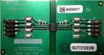
Figure 4 shows the photograph of the EVM.
Figure 4. ISO77xxD/ISO70xxD-EVM Photograph
SLAU695A – November 2016 – Revised February 2019
Submit Documentation Feedback
ISO77xxD/ISO70xxD Single- and Dual-Digital Isolator Evaluation Module
Copyright © 2016–2019, Texas Instruments Incorporated
3
�EVM Setup and Operation
5
www.ti.com
EVM Setup and Operation
This section describes the setup and operation of the EVM for parameter performance evaluation.
Figure 5 shows the configuration for operating the ISO77xxD/ISO70xxD single- and dual-digital isolator
EVM using two power supplies.
VCC1 GND1
VCC2 GND2
Signal
Generator
Scope
CHx
CHx
Figure 5. Basic EVM Operation
Figure 6 shows typical input and output waveforms of the EVM for a 1-MHz clock. The input is shown as
channel 1, and the output is shown as channel 2.
Figure 6. Typical Input and Output Waveform
4
ISO77xxD/ISO70xxD Single- and Dual-Digital Isolator Evaluation Module
SLAU695A – November 2016 – Revised February 2019
Submit Documentation Feedback
Copyright © 2016–2019, Texas Instruments Incorporated
�Bill of Materials
www.ti.com
6
Bill of Materials
Table 1 shows the bill of materials (BOM) for this EVM.
Table 1. Bill of Materials
Item
Designator
Description
Manufacturer
Part Number
Quantity
MuRata
GRM21BR6YA106KE43L
2
MuRata
GRM188R61H105KAALD
2
1
C1, C4
CAP, CERM, 10 µF, 35 V, ±
10%, X5R, 0805
2
C2, C5
CAP, CERM, 1 µF, 50 V, ± 10%,
X5R, 0603
3
C3, C6
CAP, CERM, 0.1 µF, 25 V, ± 5%,
AVX
X7R, 0603
06033C104JAT2A
2
4
H1, H2, H3, H4
Bumpon, Hemisphere, 0.44 X
0.20, Clear
3M
SJ-5303 (CLEAR)
4
Header, 100mil, 4x2, Gold, SMT
Molex
15910080
2
Test Point, Miniature, SMT
Keystone
5019
8
Robust EMC, Low Power, DualChannel Digital Isolators,
D0008B (SOIC-8)
Texas Instruments
ISO7721DR
1
5
J1, J2
6
TP1, TP2, TP3, TP4,
TP5, TP6, TP7, TP8
7
U1
7
EVM Schematics and Layout
The ISO7721DEVM is designed to accommodate any of the ISO77xxD/ISO70xxD single- and dualchannel devices in an 8-pin D package. To evaluate any of the ISO77xxD/ISO70xxD single- and dualchannel devices in an 8-pin D package, replace ISO7721D with the device of interest on the
ISO7721DEVM PCB. No other component requires any modification. Figure 7 shows the
ISO77xxD/ISO70xxD EVM schematic and Figure 8 shows the printed-circuit board (PCB) layout.
VCC1
TP1
TP2 TP3 TP4
TP5 TP6 TP7
U1
VCC1
1
Vin: 2.25V - 5.5V (0.2A)
1
3
5
7
GND1
2
4
6
8
2
J1
TP8
VCC2
VCC2
VCC1
VCC2
OUTA
INA
8
Vin: 2.25V - 5.5V (0.2A)
GND2
1
3
5
7
7
3
INB
OUTB
6
4
GND1
GND2
5
2
4
6
8
J2
GND1
GND2
ISO7721D
GND1
GND1
GND2
VCC1
GND2
VCC2
C1
C2
C3
C6
C5
C4
10µF
1µF
0.1µF
0.1µF
1µF
10µF
GND1
GND2
Copyright © 2016, Texas Instruments Incorporated
Figure 7. ISO77xxD/ISO70xxD EVM Schematic
SLAU695A – November 2016 – Revised February 2019
Submit Documentation Feedback
ISO77xxD/ISO70xxD Single- and Dual-Digital Isolator Evaluation Module
Copyright © 2016–2019, Texas Instruments Incorporated
5
�EVM Schematics and Layout
www.ti.com
Figure 8. ISO77xxD/ISO70xxD PCB Layout
6
ISO77xxD/ISO70xxD Single- and Dual-Digital Isolator Evaluation Module
SLAU695A – November 2016 – Revised February 2019
Submit Documentation Feedback
Copyright © 2016–2019, Texas Instruments Incorporated
�IMPORTANT NOTICE AND DISCLAIMER
TI PROVIDES TECHNICAL AND RELIABILITY DATA (INCLUDING DATA SHEETS), DESIGN RESOURCES (INCLUDING REFERENCE
DESIGNS), APPLICATION OR OTHER DESIGN ADVICE, WEB TOOLS, SAFETY INFORMATION, AND OTHER RESOURCES “AS IS”
AND WITH ALL FAULTS, AND DISCLAIMS ALL WARRANTIES, EXPRESS AND IMPLIED, INCLUDING WITHOUT LIMITATION ANY
IMPLIED WARRANTIES OF MERCHANTABILITY, FITNESS FOR A PARTICULAR PURPOSE OR NON-INFRINGEMENT OF THIRD
PARTY INTELLECTUAL PROPERTY RIGHTS.
These resources are intended for skilled developers designing with TI products. You are solely responsible for (1) selecting the appropriate
TI products for your application, (2) designing, validating and testing your application, and (3) ensuring your application meets applicable
standards, and any other safety, security, regulatory or other requirements.
These resources are subject to change without notice. TI grants you permission to use these resources only for development of an
application that uses the TI products described in the resource. Other reproduction and display of these resources is prohibited. No license
is granted to any other TI intellectual property right or to any third party intellectual property right. TI disclaims responsibility for, and you
will fully indemnify TI and its representatives against, any claims, damages, costs, losses, and liabilities arising out of your use of these
resources.
TI’s products are provided subject to TI’s Terms of Sale or other applicable terms available either on ti.com or provided in conjunction with
such TI products. TI’s provision of these resources does not expand or otherwise alter TI’s applicable warranties or warranty disclaimers for
TI products.
TI objects to and rejects any additional or different terms you may have proposed. IMPORTANT NOTICE
Mailing Address: Texas Instruments, Post Office Box 655303, Dallas, Texas 75265
Copyright © 2022, Texas Instruments Incorporated
�