User's Guide
SNLU194A – November 2015 – Revised July 2017
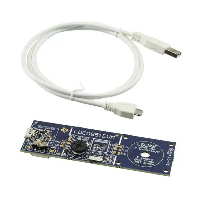
LDC0851EVM
The Texas Instruments LDC0851 evaluation module (EVM) helps designers evaluate the operation and
performance of the LDC0851 Inductive Switch. The EVM contains one LDC0851 soldered onto the EVM
PCB and options to operate with battery or USB power. A 50-kΩ trim pot is also included to change the
switching distance threshold making it easy to evaluate for a wide variety of use cases.
Table 1. Device and Package Configurations
DEVICE
IC
PACKAGE
U1
LDC0851
WSON-8
Figure 1. LDC0851EVM
1
2
3
4
5
6
Contents
EVM Features and Connections ........................................................................................... 3
Theory of Operation ......................................................................................................... 6
Quick Start Guide .......................................................................................................... 10
EVM Design – Board Layout ............................................................................................. 14
EVM Design - Schematic .................................................................................................. 16
EVM Bill of Materials ....................................................................................................... 18
List of Figures
1
LDC0851EVM ................................................................................................................ 1
2
EVM Block Diagram ......................................................................................................... 3
3
Connector and Feature Locations (Top) .................................................................................. 4
4
Connector and Feature Locations (Bottom) .............................................................................. 4
5
EVM Break-Away Sections ................................................................................................. 5
6
Break-Away Sensor (Top) .................................................................................................. 5
7
Break-Away Sensor (Bottom) .............................................................................................. 5
8
Simplified Block Diagram for Stacked Coils .............................................................................. 6
9
Switch Distance with Offset
................................................................................................
SNLU194A – November 2015 – Revised July 2017
Submit Documentation Feedback
Copyright © 2015–2017, Texas Instruments Incorporated
LDC0851EVM
7
1
�www.ti.com
10
Adjust the Offset ............................................................................................................. 7
11
Switching Distance of 20mm Stacked Coil ............................................................................... 9
12
Stacked Coil Separation .................................................................................................... 9
13
Insert 5-V Micro-USB ...................................................................................................... 10
14
Set SUPPLY Switch (S2) to USB ........................................................................................ 10
15
Insert CR2032 Battery into BT1 .......................................................................................... 11
16
Change SUPPLY Switch (S2) to BAT ................................................................................... 11
17
Adjust the Offset ............................................................................................................ 12
18
Toggle Enable to Set New Threshold ................................................................................... 12
19
Observe Status of OUT LED
20
Bring Metal Target Close to LSENSE ................................................................................... 13
21
ESD Compliance ........................................................................................................... 14
22
Top Layer Routing
14
23
Bottom Layer Routing
15
24
25
26
27
.............................................................................................
.........................................................................................................
.....................................................................................................
Mid-Layer 1 Routing .......................................................................................................
Mid-Layer 2 Routing .......................................................................................................
Battery, LDC0851, and Sensor ...........................................................................................
Optional 5-V Micro-USB to 3.0 V .........................................................................................
13
15
15
16
17
List of Tables
1
Device and Package Configurations ...................................................................................... 1
2
EVM Connections............................................................................................................ 3
3
LED Indicator Behavior with GUI .......................................................................................... 4
4
LDC0851EVM Sensor Parameters ........................................................................................ 6
5
Resistor Values for ADJ Code ............................................................................................. 8
6
Battery Requirements...................................................................................................... 11
7
Layer Usage
8
Bill of Materials
................................................................................................................
.............................................................................................................
14
18
Trademarks
All trademarks are the property of their respective owners.
2
LDC0851EVM
SNLU194A – November 2015 – Revised July 2017
Submit Documentation Feedback
Copyright © 2015–2017, Texas Instruments Incorporated
�EVM Features and Connections
www.ti.com
1
EVM Features and Connections
This section describes the connectors on the LDC0851EVM and how to properly connect, set up and use
the LDC0851.
Approaching Metal Target
Breakaway Portion 2
Breakaway Portion 1
VDD
5V
µUSB
(J3)
5V
VDD
LP5951
3.0-V Out LDO
1.8V
3.0 V
Coin Cell Battery
CR2032 - 3.0 V
(BT1)
ADJ
3.0 V
LREF
LSENSE
LDC0851
(WSON8)
LR
LS
LC
J1
LSENSE Sensor
20 mm O.D.
7 turns/layer
6 mil trace
6 mil space
2 Layer
6.2 µH
LR
LS
LC
LCOM
USB
J4
BAT
50-kO Trim Pot
(R5)
EN
OUT
LREF Sensor
Output
LED
(D3)
Supply Switch, SPDT
(S2)
VDD
VDD
VDD
Enable Toggle Switch, SPDT
(S2)
Figure 2. EVM Block Diagram
1.1
Connector Description
Table 2. EVM Connections
CONNECTOR
TYPE
FUNCTIONALITY
J1
6 pin, 100 mil header (not stuffed)
Provides connections for LREF, LSENSE, and LCOM if sensor portion is detached.
J2
2 pin, 100 mil header (not stuffed)
Provides connections for GND and VDD if the power section is detached.
J3
Micro-USB connector
Provides 3.0-V power to the DUT when connected to 5 V.
BT1 – CR2032
CR2032 Battery Holder
Provides 3.0-V power to the DUT when CR2032 battery is inserted into the battery
slot.
J4
4 pin, 100 mil header (not stuffed)
Provides optional connections for DUT Supply, Ground, OUT, and EN.
S1 – EN RESET
SPDT Switch
Spring loaded switch (default on) to toggle EN low. This resamples the voltage on the
ADJ pin.
S2
SPDT Switch
Toggle between 3.0-V USB Power (USB position) and 3.0-V battery power (BAT
position).
D3 – OUT
Green LED
Indicates when the output of the LDC0851 switches. Note that LED will be off in the
absence of a metal target.
D5
Green LED (not stuffed)
Indicates 3.0 V is present at output of the 3.0-V LDO (LP5951).
R5 – OFFSET
ADJUST
50k Trim Pot
Provides adjustable resistance to create a voltage divider between 0 V and VDD/2 on
the ADJ pin. If the voltage is changed during operation, the EN pin must be toggled
low then high with switch S1.
Breakaway
Perforation 1
Perforation
The EVM can be separated at this point to use a different supply rail or to directly
access VDD, GND, OUT, and EN.
Breakaway
Perforation 2
Perforation
The EVM can be separated at this point to use different LSENSE and LREF sensors.
USB
Test Point
Test point for 3.0-V output of LP5951.
BAT
Test Point
Test point for 3.0-V output of Battery
SNLU194A – November 2015 – Revised July 2017
Submit Documentation Feedback
Copyright © 2015–2017, Texas Instruments Incorporated
LDC0851EVM
3
�EVM Features and Connections
www.ti.com
Figure 3. Connector and Feature Locations (Top)
Figure 4. Connector and Feature Locations (Bottom)
1.2
EVM Interface
The LDC0851EVM can be powered with 5 V via the micro-USB connection (J3) on the top side of the
EVM. Alternatively, a 3-V battery via the battery connection (BT1) on the backside of the EVM may be
used to directly supply the LDC0851 with 3 V. Use Supply Switch (S2) to select the desired power source.
The voltage on the ADJ pin of the LDC0851 at startup will determine the distance at which a metal target
will be detected. The voltage can be easily controlled through the 50-kΩ trim pot (R5). Note, the ADJ value
is only sampled once on startup or after EN has toggled low to high with switch S1.
Table 3. LED Indicator Behavior with GUI
4
LED
COLOR
FUNCTIONALITY
D3
Green
Indicates when the output of the LDC0851 switches.
LDC0851EVM
SNLU194A – November 2015 – Revised July 2017
Submit Documentation Feedback
Copyright © 2015–2017, Texas Instruments Incorporated
�EVM Features and Connections
www.ti.com
1.3
Break-Away Sections
Figure 5. EVM Break-Away Sections
The LDC0851 EVM can be broken into 3 discrete sections: a 5-V to 3-V section which includes the USB
interface section, an LDC0851 section, and a sensor section which contains the LREF and LSENSE
sensors.
Figure 6. Break-Away Sensor (Top)
Figure 7. Break-Away Sensor (Bottom)
Break-Away Sensor Section: The Sensor section of the LDC0851EVM can be broken along the
indicated line to separate the sensor from the LDC0851 IC. A three pin header is available on the
LDC0851 section to connect to different sensors or for remote location. If the cable connection between
the sensor and the LDC0851EVM is longer than 2 cm, use twisted pair or coaxial to connect back to the
LDC0851 section.
The EVM sensor is a 4 layer stacked coil design, with the top 2 layers used for the sensing coil, and the
bottom 2 layers used for the reference coil.
SNLU194A – November 2015 – Revised July 2017
Submit Documentation Feedback
Copyright © 2015–2017, Texas Instruments Incorporated
LDC0851EVM
5
�Theory of Operation
www.ti.com
Table 4. LDC0851EVM Sensor Parameters
2
PARAMETER
LSENSE SENSOR VALUE
LREF SENSOR VALUE
Outer Diameter
787.4 mils (20.0 mm)
787.4 mils (20.0 mm)
Inner Diameter
619.4 mils (15.7 mm)
619.4 mils (15.7 mm)
Number of turns
7
7
Trace Width
6 mils (0.152 mm)
6 mils (0.152 mm)
Trace Spacing
6 mils (0.152 mm)
6 mils (0.152 mm)
Number of layers
2
2
Trace Thickness
1 oz-cu (35 μm)
1 oz-cu (35 μm)
Inductance at 9.5 MHz
8.65 µH
8.65 µH
CSENSOR (C4)
68 pF
68 pF
ƒSENSOR (no target)
9.5 MHz
9.5 MHz
Theory of Operation
The LDC0851 is an inductance based switch for contactless and robust applications such as presence
detection, event counting, and coarse position detection. The device is connected to a reference coil
(LREF) and a sensing coil (LSENSE). The output of the LDC0851 switches when the inductance of
LSENSE drops below LREF which is caused by an approaching metal target. The LDC0851 EVM
employs a stacked coil arrangement, in which the LSENSE sensor coil is closer to the metal target than
the LREF reference coil when approached from the top side (LSENSE side). The user can take advantage
of the Offset Adjust feature to change the switching distance (dswitch). The offset is added to LREF so
that increasing the ADJ code causes the LDC0851 to switch at a closer distance. The ADJ code is
determined by the voltage level on the ADJ pin at device power on and by toggling the Enable pin low
then high.
LDC0851
LSENSE
Switching distance set
by ADJ Value
LREF
Approaching
Metal Target
...
Sense
Coil
Ref
Coil
Differential Inductive
Switch
LCOM
ADJ =1 ADJ =15
Sensor
Cap
Mode Select
0: Reference switch
1 ± 15: Threshold Adjust
VDD
R3
53.6 k
ADJ
4-bit ADC
R5
50 k
R4
3.56 k
Figure 8. Simplified Block Diagram for Stacked Coils
6
LDC0851EVM
SNLU194A – November 2015 – Revised July 2017
Submit Documentation Feedback
Copyright © 2015–2017, Texas Instruments Incorporated
�Theory of Operation
www.ti.com
Coil
Inductance
LSENSE
Adjusted LREF
(ADJ = 1)
Y
Adjusted LREF
(ADJ = 15)
dswitch
C 0.3x(dcoil)
(ADJ = 1)
dswitch
(ADJ = 15)
Target
Distance
Figure 9. Switch Distance with Offset
A potentiometer (R5) has been included to make adjusting the threshold easier for prototyping. Note that
rotating the potentiometer clockwise towards the MIN direction decreases the ADJ value and results in a
longer switching threshold. Similarly, rotating R5 counter clockwise towards the MAX position increases
the ADJ value and decreases the switching distance. The Enable pin should be toggled low then high to
set a new switching threshold.
Figure 10. Adjust the Offset
The ADJ value can be achieved by setting the combination of R4 + R5 to the values in Table 5.
SNLU194A – November 2015 – Revised July 2017
Submit Documentation Feedback
Copyright © 2015–2017, Texas Instruments Incorporated
LDC0851EVM
7
�Theory of Operation
www.ti.com
Table 5. Resistor Values for ADJ Code
ADJ Level (code)
R4+R5 (kΩ)
1
3.57
2
5.54
3
7.66
4
9.93
5
12.37
6
15.01
7
17.87
8
20.97
9
24.36
10
28.08
11
32.16
12
36.67
13
41.69
14
47.29
15
53.60
The switching distance for stacked coils can be approximated with Equation 1.
ADJCode ·
§
dswitch dcoil u 0.3x ¨ 1
¸
16
©
¹
where
•
•
•
dswitch is the approximated switching distance for a stacked coil sensor with good separation between
LSENSE coil layers and LREF coil layers. Note that for side-by-side coils, the switching distance uses
a factor of 0.4.
dcoil is the coil diameter
ADJCode is the desired value from Table 5
(1)
For example, consider a coil with a diameter of 20 mm. An ADJ code of 1 yields a switching distance of
5.6 mm, and an ADJ code of 15 yields a switching distance of 0.375 mm. This method helps approximate
the switching distance, but the actual response of the coils may vary slightly which is why it is important to
prototype the coil as can be seen in Figure 11 below.
8
LDC0851EVM
SNLU194A – November 2015 – Revised July 2017
Submit Documentation Feedback
Copyright © 2015–2017, Texas Instruments Incorporated
�Theory of Operation
www.ti.com
8
Switch ON
Switch OFF
Switching Distance (mm)
7
6
5
4
3
2
1
0
1
2
3
4
5
6
7 8 9
ADJ Code
10 11 12 13 14 15
D001
Figure 11. Switching Distance of 20mm Stacked Coil
It should be noted that the sensing distance is determined by the diameter of the coils, inductance
matching, and the spacing or PCB thickness between the LSENSE coil and LREF coil layers. To achieve
the maximum sensing range for stacked coils, the spacing (h) between the LSENSE and LREF coils
should be as thick as possible. Refer to Figure 12 below.
Layers 1, 2
Sense Coil
h
Layers 3, 4
Reference Coil
Figure 12. Stacked Coil Separation
It is also recommended to use a target of equal or larger size to the coil diameter to get the longest
sensing range.
SNLU194A – November 2015 – Revised July 2017
Submit Documentation Feedback
Copyright © 2015–2017, Texas Instruments Incorporated
LDC0851EVM
9
�Quick Start Guide
www.ti.com
3
Quick Start Guide
3.1
Supply Power to the LDC0851EVM
Power can be supplied either through the 5-V micro-USB connection (J3) or through the 3.0-V battery slot
(BT1) on the backside of the EVM.
3.1.1
5-V Micro-USB to 3-V Device Power
Connect a USB cable between the 5-V source and the micro-USB connector (J3) on EVM. An onboard
LDO will convert the 5-V source into 3.0 V which can be measured at the USB test point shown below.
Figure 13. Insert 5-V Micro-USB
Verify that SUPPLY Switch (S2) is in the USB position.
Figure 14. Set SUPPLY Switch (S2) to USB
10
LDC0851EVM
SNLU194A – November 2015 – Revised July 2017
Submit Documentation Feedback
Copyright © 2015–2017, Texas Instruments Incorporated
�Quick Start Guide
www.ti.com
3.1.2
3-V Battery Power
Alternatively, the LDC0851 may be operated from battery power. The list of battery requirements is
provided below:
Table 6. Battery Requirements
Parameter
Specification
Battery Model
CR2032 UL Certified Battery
Voltage
3.0 V
Min Capacity
225 mAh
Min Discharge Rate
200 µA
Manufacturer and Model Number
Panasonic - BSG CR2032 (or equivalent)
When the EVM is powered by the battery, it is not necessary to have a micro-USB cable connected to J3.
Insert CR2032 battery in the slot (BT1) on the back of the board. A voltage of 3.0 V can be measured at
the BAT test point shown below.
Figure 15. Insert CR2032 Battery into BT1
Slide SUPPLY switch (S2) to the BAT position.
Figure 16. Change SUPPLY Switch (S2) to BAT
SNLU194A – November 2015 – Revised July 2017
Submit Documentation Feedback
Copyright © 2015–2017, Texas Instruments Incorporated
LDC0851EVM
11
�Quick Start Guide
3.2
www.ti.com
Adjust the Threshold
The EVM has a potentiometer (R5) which can be used to control the voltage level on the ADJ pin. Rotate
the pot clockwise towards “MIN” so that ADJ value is in the minimum offset position, which has the longest
sensing range.
Figure 17. Adjust the Offset
To set a new threshold, toggle the EN RESET switch (S1) to re-sample the ADJ pin. This must be done
every time a new threshold is set.
Figure 18. Toggle Enable to Set New Threshold
12
LDC0851EVM
SNLU194A – November 2015 – Revised July 2017
Submit Documentation Feedback
Copyright © 2015–2017, Texas Instruments Incorporated
�Quick Start Guide
www.ti.com
3.3
Detecting presence of Metal Targets
With no target is present the OUTPUT LED (D3) should be off. If D3 is on or remains on, increase the
offset with R5 and toggle EN with S1 as shown in the previous step.
Figure 19. Observe Status of OUT LED
Bring a conductive target close to the LSENSE coil. The OUT LED (D3) should turn on when the target is
1 to 8 mm above the EVM sensing coil depending on the ADJ value.
Figure 20. Bring Metal Target Close to LSENSE
To change the switching threshold simply adjust the value of R5, toggle EN with S1 and retest. Note that
during active operation the ADJ pin draws ~10 µA of current will alter the resistance reading if using a
multi meter to check the value. In order to properly set or check the ADJ resistance when using a multi
meter, turn off the device, remove the battery, and set S2 to BAT. The resistance measured across R4 +
R5 should be set according to Table 5 for a desired ADJ setting.
This process can be repeated and fine-tuned for a variety of applications including open/close proximity
switches, white goods, home security and tamper detection, e-meters, and printers.
SNLU194A – November 2015 – Revised July 2017
Submit Documentation Feedback
Copyright © 2015–2017, Texas Instruments Incorporated
LDC0851EVM
13
�Quick Start Guide
3.4
www.ti.com
PCB Breakoff Sections and Compliance
The different sections of the EVM may be broken apart for ease of prototyping and development. Please
note that breaking apart the sections voids the warranty. In addition, the stated performance and
compliance specifications of the EVM cannot be guaranteed when sections have been broken apart.
The LDC0851EVM has the ability to be powered by either connecting a USB cable or by a 3 V battery as
mentioned in Section 3.1. Compliance was evaluated with both Battery powered and USB powered
options. Note that if a USB cable is used for powering the EVM, ferrites need to be added to each end of
the cable. Fair-rite, Model #0431164951 (or equivalent) are to be installed with one turn each at each end
when a USB cable is used for powering the EVM. If provided, the shielded USB cable is less than 3m in
length. If not, and one is to be purchased for use with this EVM, it is required to be no longer than 3m to
retain the stated performance and compliance.
ATTENTION
STATIC SENSITIVE DEVICES
HANDLE ONLY AT
STATIC SAFE WORK STATIONS
Figure 21. ESD Compliance
CAUTION
The EVM contains components that can potentially be damaged by electrostatic
discharge. Always transport and store the EVM in the supplied ESD bag when
not in use. Handle using an antistatic wristband. Operate on an antistatic work
surface. For more information on proper handling, refer to Electrostatic
Discharge (ESD)[SSYA010].
4
EVM Design – Board Layout
Table 7. Layer Usage
LAYER
FUNCTIONALITY
Top
Signals, Components, Sense coil, and ground-fill
Mid-layer 1
Sense coil, and section transition routing
Mid-layer 2
Reference coil, and section transition routing
Bottom
Signals, Components, Reference coil, and ground-fill
Figure 22. Top Layer Routing
14
LDC0851EVM
SNLU194A – November 2015 – Revised July 2017
Submit Documentation Feedback
Copyright © 2015–2017, Texas Instruments Incorporated
�EVM Design – Board Layout
www.ti.com
Figure 23. Bottom Layer Routing
Figure 24. Mid-Layer 1 Routing
Figure 25. Mid-Layer 2 Routing
SNLU194A – November 2015 – Revised July 2017
Submit Documentation Feedback
Copyright © 2015–2017, Texas Instruments Incorporated
LDC0851EVM
15
�EVM Design - Schematic
5
www.ti.com
EVM Design - Schematic
Figure 26. Battery, LDC0851, and Sensor
16
LDC0851EVM
SNLU194A – November 2015 – Revised July 2017
Submit Documentation Feedback
Copyright © 2015–2017, Texas Instruments Incorporated
�EVM Design - Schematic
www.ti.com
Figure 27. Optional 5-V Micro-USB to 3.0 V
SNLU194A – November 2015 – Revised July 2017
Submit Documentation Feedback
LDC0851EVM
Copyright © 2015–2017, Texas Instruments Incorporated
17
�EVM Bill of Materials
6
www.ti.com
EVM Bill of Materials
Table 8. Bill of Materials
ITEM
#
DESIGNATOR
PART NUMBER
MANUFACTURER
DESCRIPTION
1
!PCB1
SV601198
Any
Printed Circuit Board
2
BT1
BK-912
Memory Protection Devices
Battery Holder for CR2032, SMT
3
C1
C1005X7R1H104K
TDK
CAP, CERM, 0.1 µF, 50 V, +/- 10%,
X7R, 0402
4
C2
C0603C105K4PACTU
Kemet
CAP, CERM, 1 µF, 16 V, +/- 10%, X5R,
0603
5
C4
C1608C0G1H680J
TDK
CAP, CERM, 68 pF, 50 V, +/- 5%,
C0G/NP0, 0603
6
C5
EMK212BB7106MG-T
Taiyo Yuden
CAP, CERM, 10 µF, 16 V, +/- 20%, X7R,
0805
7
C6, C7
C0603C104J3RAC
Kemet
CAP, CERM, 0.1 µF, 25 V, +/- 5%, X7R,
0603
8
C8
C2012X7S1A226M125A
C
TDK
CAP, CERM, 22 µF, 10 V, +/- 20%, X7S,
0805
9
C9
GRM188R71A225KE15
D
MuRata
CAP, CERM, 2.2 µF, 10 V, +/- 10%,
X7R, 0603
10
D1
MMSZ4685-V
Vishay-Semiconductor
Diode, Zener, 3.6 V, 500 mW, SOD-123
11
D3
LG L29K-G2J1-24-Z
OSRAM
LED, Green, SMD
12
D4
MMSZ5232B-7-F
Diodes Inc.
Diode, Zener, 5.6 V, 500 mW, SOD-123
13
FID6
N/A
N/A
Fiducial mark. There is nothing to buy or
mount.
14
J3
ZX62R-B-5P
Hirose Electric Co. Ltd.
Connector, Receptacle, Micro-USB Type
B, SMT
15
L1
VLS201610ET-100M
TDK
Inductor, Shielded, Ferrite, 10 µH, 0.4 A,
1.38 ohm, SMD
16
LBL1
THT-14-423-10
Brady
Thermal Transfer Printable Labels,
0.650" W x 0.200" H - 10,000 per roll
17
R2
CRCW0402200RFKED
Vishay-Dale
RES, 200, 1%, 0.063 W, 0402
18
R3
RC0603FR-0753K6L
Yageo America
RES, 53.6 k, 1%, 0.1 W, 0603
19
R4
CRCW06033K57FKEA
Vishay-Dale
RES, 3.57 k, 1%, 0.1 W, 0603
20
R5
3352T-1-503LF
Bourns
Trimming Potentiometer, 50K, 0.5W, TH
21
R7
CRCW060333R0JNEA
Vishay-Dale
RES, 33, 5%, 0.1 W, 0603
C&K Components
Switch, SPDT, On-Mom, 1 Pos, 0.01A, 5
VDC, SMD
Switch, Slide, SPDT, 0.2A, J Lead, SMD
22
S1
JSX08001SAQNL
23
S2
CL-SB-12A-01T
Copal Electronics
24
U1
LDC0851DSGR
Texas Instruments
1.8-3.3V Inductive Switch, DSG0008A
Texas Instruments
Micropower, 150mA Low-Dropout CMOS
Voltage Regulator, 5-pin SC-70, Pb-Free
25
18
LDC0851EVM
U2
LP5951MG-3.0/NOPB
SNLU194A – November 2015 – Revised July 2017
Submit Documentation Feedback
Copyright © 2015–2017, Texas Instruments Incorporated
�Revision History
www.ti.com
Revision History
NOTE: Page numbers for previous revisions may differ from page numbers in the current version.
Changes from Original (November 2015) to A Revision ................................................................................................ Page
•
•
Changed to new ug layout ............................................................................................................... 3
Added PCB Breakoff Sections and Compliance section ........................................................................... 14
SNLU194A – November 2015 – Revised July 2017
Submit Documentation Feedback
Copyright © 2015–2017, Texas Instruments Incorporated
Revision History
19
�IMPORTANT NOTICE FOR TI DESIGN INFORMATION AND RESOURCES
Texas Instruments Incorporated (‘TI”) technical, application or other design advice, services or information, including, but not limited to,
reference designs and materials relating to evaluation modules, (collectively, “TI Resources”) are intended to assist designers who are
developing applications that incorporate TI products; by downloading, accessing or using any particular TI Resource in any way, you
(individually or, if you are acting on behalf of a company, your company) agree to use it solely for this purpose and subject to the terms of
this Notice.
TI’s provision of TI Resources does not expand or otherwise alter TI’s applicable published warranties or warranty disclaimers for TI
products, and no additional obligations or liabilities arise from TI providing such TI Resources. TI reserves the right to make corrections,
enhancements, improvements and other changes to its TI Resources.
You understand and agree that you remain responsible for using your independent analysis, evaluation and judgment in designing your
applications and that you have full and exclusive responsibility to assure the safety of your applications and compliance of your applications
(and of all TI products used in or for your applications) with all applicable regulations, laws and other applicable requirements. You
represent that, with respect to your applications, you have all the necessary expertise to create and implement safeguards that (1)
anticipate dangerous consequences of failures, (2) monitor failures and their consequences, and (3) lessen the likelihood of failures that
might cause harm and take appropriate actions. You agree that prior to using or distributing any applications that include TI products, you
will thoroughly test such applications and the functionality of such TI products as used in such applications. TI has not conducted any
testing other than that specifically described in the published documentation for a particular TI Resource.
You are authorized to use, copy and modify any individual TI Resource only in connection with the development of applications that include
the TI product(s) identified in such TI Resource. NO OTHER LICENSE, EXPRESS OR IMPLIED, BY ESTOPPEL OR OTHERWISE TO
ANY OTHER TI INTELLECTUAL PROPERTY RIGHT, AND NO LICENSE TO ANY TECHNOLOGY OR INTELLECTUAL PROPERTY
RIGHT OF TI OR ANY THIRD PARTY IS GRANTED HEREIN, including but not limited to any patent right, copyright, mask work right, or
other intellectual property right relating to any combination, machine, or process in which TI products or services are used. Information
regarding or referencing third-party products or services does not constitute a license to use such products or services, or a warranty or
endorsement thereof. Use of TI Resources may require a license from a third party under the patents or other intellectual property of the
third party, or a license from TI under the patents or other intellectual property of TI.
TI RESOURCES ARE PROVIDED “AS IS” AND WITH ALL FAULTS. TI DISCLAIMS ALL OTHER WARRANTIES OR
REPRESENTATIONS, EXPRESS OR IMPLIED, REGARDING TI RESOURCES OR USE THEREOF, INCLUDING BUT NOT LIMITED TO
ACCURACY OR COMPLETENESS, TITLE, ANY EPIDEMIC FAILURE WARRANTY AND ANY IMPLIED WARRANTIES OF
MERCHANTABILITY, FITNESS FOR A PARTICULAR PURPOSE, AND NON-INFRINGEMENT OF ANY THIRD PARTY INTELLECTUAL
PROPERTY RIGHTS.
TI SHALL NOT BE LIABLE FOR AND SHALL NOT DEFEND OR INDEMNIFY YOU AGAINST ANY CLAIM, INCLUDING BUT NOT
LIMITED TO ANY INFRINGEMENT CLAIM THAT RELATES TO OR IS BASED ON ANY COMBINATION OF PRODUCTS EVEN IF
DESCRIBED IN TI RESOURCES OR OTHERWISE. IN NO EVENT SHALL TI BE LIABLE FOR ANY ACTUAL, DIRECT, SPECIAL,
COLLATERAL, INDIRECT, PUNITIVE, INCIDENTAL, CONSEQUENTIAL OR EXEMPLARY DAMAGES IN CONNECTION WITH OR
ARISING OUT OF TI RESOURCES OR USE THEREOF, AND REGARDLESS OF WHETHER TI HAS BEEN ADVISED OF THE
POSSIBILITY OF SUCH DAMAGES.
You agree to fully indemnify TI and its representatives against any damages, costs, losses, and/or liabilities arising out of your noncompliance with the terms and provisions of this Notice.
This Notice applies to TI Resources. Additional terms apply to the use and purchase of certain types of materials, TI products and services.
These include; without limitation, TI’s standard terms for semiconductor products http://www.ti.com/sc/docs/stdterms.htm), evaluation
modules, and samples (http://www.ti.com/sc/docs/sampterms.htm).
Mailing Address: Texas Instruments, Post Office Box 655303, Dallas, Texas 75265
Copyright © 2017, Texas Instruments Incorporated
�