LM136-5.0, LM236-5.0, LM336-5.0
www.ti.com
SNVS750D – JUNE 1999 – REVISED MARCH 2013
LM136-5.0, LM236-5.0, LM336-5.0 5.0V Reference Diode
Check for Samples: LM136-5.0, LM236-5.0, LM336-5.0
FEATURES
DESCRIPTION
•
•
•
•
•
•
•
•
•
The LM136-5.0/LM236-5.0/LM336-5.0 integrated
circuits are precision 5.0V shunt regulator diodes.
These monolithic IC voltage references operate as a
low temperature coefficient 5.0V zener with 0.6Ω
dynamic impedance. A third terminal on the LM1365.0 allows the reference voltage and temperature
coefficient to be trimmed easily.
1
2
Adjustable 4V to 6V
Low Temperature Coefficient
Wide Operating Current of 600 μA to 10 mA
0.6Ω Dynamic Impedance
± 1% Initial Tolerance Available
Specified Temperature Stability
Easily Trimmed for Minimum Temperature Drift
Fast Turn-on
Three Lead Transistor Package
The LM136-5.0 series is useful as a precision 5.0V
low voltage reference for digital voltmeters, power
supplies or op amp circuitry. The 5.0V makes it
convenient to obtain a stable reference from low
voltage supplies. Further, since the LM136-5.0
operates as a shunt regulator, it can be used as
either a positive or negative voltage reference.
The LM136-5.0 is rated for operation over −55°C to
+125°C while the LM236-5.0 is rated over a −25°C to
+85°C temperature range. The LM336-5.0 is rated for
operation over a 0°C to +70°C temperature range.
See the Connection Diagrams for available packages.
For applications requiring 2.5V see LM136-2.5.
Connection Diagrams
Figure 1. TO-92 Plastic Package
(Bottom View)
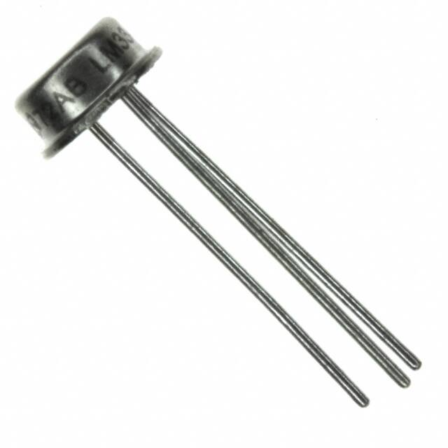
Figure 2. TO Metal Can Package
(Bottom View)
Figure 3. SOIC Package
1
2
Please be aware that an important notice concerning availability, standard warranty, and use in critical applications of
Texas Instruments semiconductor products and disclaimers thereto appears at the end of this data sheet.
All trademarks are the property of their respective owners.
PRODUCTION DATA information is current as of publication date.
Products conform to specifications per the terms of the Texas
Instruments standard warranty. Production processing does not
necessarily include testing of all parameters.
Copyright © 1999–2013, Texas Instruments Incorporated
�LM136-5.0, LM236-5.0, LM336-5.0
SNVS750D – JUNE 1999 – REVISED MARCH 2013
www.ti.com
Typical Applications
Figure 4. 5.0V Reference
† Adjust to 5.00V
* Any silicon signal diode
Figure 5. 5.0V Reference with Minimum
Temperature Coefficient
* Does not affect temperature coefficient
Figure 6. Trimmed 4V to 6V Reference
with Temperature Coefficient
Independent of Breakdown Voltage
2
Submit Documentation Feedback
Copyright © 1999–2013, Texas Instruments Incorporated
Product Folder Links: LM136-5.0 LM236-5.0 LM336-5.0
�LM136-5.0, LM236-5.0, LM336-5.0
www.ti.com
SNVS750D – JUNE 1999 – REVISED MARCH 2013
These devices have limited built-in ESD protection. The leads should be shorted together or the device placed in conductive foam
during storage or handling to prevent electrostatic damage to the MOS gates.
ABSOLUTE MAXIMUM RATINGS
(1)
Reverse Current
15
mA
Forward Current
10
mA
−60 to +150
°C
LM136-5.0
−55 to +150
°C
LM236-5.0
−25 to +85
°C
LM336-5.0
0 to +70
°C
TO-92 Package (10 sec.)
260
°C
TO Package (10 sec.)
300
°C
Vapor Phase (60 sec.)
215
°C
Infrared (15 sec.)
220
°C
Storage Temperature
Operating Temperature Range
(2)
Soldering Information
SOIC Package
(1)
(2)
Absolute Maximum Ratings indicate limits beyond which damage to the device may occur. Electrical specifications do not apply when
operating the device beyond its specified operating conditions.
For elevated temperature operation, Tj max see THERMAL CHARACTERISTICS
THERMAL CHARACTERISTICS
over operating free-air temperature range (unless otherwise noted)
LM136
150°C
LM236
125°C
LM336
100°C
Thermal Resistance
θja (Junction to Ambient)
TO-92
180°C/W (0.4″ Leads)
TO
SOIC-8
440°C/W
165°C/W
80°C/W
N/A
170°C/W (0.125″ Leads)
θja (Junction to Case)
N/A
ELECTRICAL CHARACTERISTICS
Parameter
Reverse Breakdown
Voltage
Conditions
LM136A-5.0/LM236A-5.0
LM336B-5.0
LM136-5.0/LM236-5.0
LM336-5.0
Min
Typ
LM136-5.0/LM236-5.0/LM336-5.0
4.9
5.00
LM136A-5.0/LM236A-5.0, LM336B-5.0
4.95
5.00
6
0.6
Max
Units
Min
Typ
Max
5.1
4.8
5.00
5.2
5.05
4.90
5.00
5.1
V
12
6
20
mV
1.2
0.6
2
Ω
4
12
mV
TA=25°C, IR=1 mA
Reverse Breakdown
Change
TA=25°C,
With Current
600 μA≤IR≤10 mA
Reverse Dynamic
Impedance
TA=25°C, IR=1 mA, f = 100 Hz
V
Temperature Stability VR Adjusted 5.00V
(2)
IR=1 mA, (Figure 15)
0°C≤TA≤70°C (LM336-5.0)
(1)
(2)
Unless otherwise specified, the LM136-5.0 is specified from −55°C≤TA≤+125°C, the LM236-5.0 from −25°C≤TA≤+85°C and the LM3365.0 from 0°C≤TA≤+70°C.
Temperature stability for the LM336 and LM236 family is specified by design. Design limits are specified (but not 100% percent
production tested) over the indicated temperature and supply voltage ranges. These limits are not used to calculate outgoing quality
levels. Stability is defined as the maximum charge in VREF from 25°C to TA(min) or TA(max).
Copyright © 1999–2013, Texas Instruments Incorporated
Product Folder Links: LM136-5.0 LM236-5.0 LM336-5.0
Submit Documentation Feedback
3
�LM136-5.0, LM236-5.0, LM336-5.0
SNVS750D – JUNE 1999 – REVISED MARCH 2013
www.ti.com
ELECTRICAL CHARACTERISTICS (continued)
(1)
LM136A-5.0/LM236A-5.0
Parameter
Conditions
LM136-5.0/LM236-5.0
Min
Reverse Breakdown
Change
LM336B-5.0
LM336-5.0
Min
Typ
Units
Typ
Max
Max
−25°C≤TA≤+85°C (LM236-5.0)
7
18
mV
−55°C≤TA≤+125°C (LM136-5.0)
20
36
mV
600 μA≤IR≤10 mA
6
17
6
1.6
0.8
24
mV
2.5
Ω
With Current
Adjustment Range
Circuit of Figure 14
±1
Reverse Dynamic
Impedance
IR = 1 mA
0.8
Long Term Stability
TA=25°C±0.1°C, IR=1 mA, t = 1000 hrs
20
4
Submit Documentation Feedback
±1
20
V
ppm
Copyright © 1999–2013, Texas Instruments Incorporated
Product Folder Links: LM136-5.0 LM236-5.0 LM336-5.0
�LM136-5.0, LM236-5.0, LM336-5.0
www.ti.com
SNVS750D – JUNE 1999 – REVISED MARCH 2013
TYPICAL PERFORMANCE CHARACTERISTICS
Reverse Voltage Change
Zener Noise Voltage
Figure 7.
Figure 8.
Dynamic Impedance
Response Time
Figure 9.
Figure 10.
Reverse Characteristics
Temperature Drift
Figure 11.
Figure 12.
Copyright © 1999–2013, Texas Instruments Incorporated
Product Folder Links: LM136-5.0 LM236-5.0 LM336-5.0
Submit Documentation Feedback
5
�LM136-5.0, LM236-5.0, LM336-5.0
SNVS750D – JUNE 1999 – REVISED MARCH 2013
www.ti.com
TYPICAL PERFORMANCE CHARACTERISTICS (continued)
Forward Characteristics
Figure 13.
6
Submit Documentation Feedback
Copyright © 1999–2013, Texas Instruments Incorporated
Product Folder Links: LM136-5.0 LM236-5.0 LM336-5.0
�LM136-5.0, LM236-5.0, LM336-5.0
www.ti.com
SNVS750D – JUNE 1999 – REVISED MARCH 2013
APPLICATION HINTS
The LM136-5.0 series voltage references are much easier to use than ordinary zener diodes. Their low
impedance and wide operating current range simplify biasing in almost any circuit. Further, either the breakdown
voltage or the temperature coefficient can be adjusted to optimize circuit performance.
Figure 14 shows an LM136-5.0 with a 10k potentiometer for adjusting the reverse breakdown voltage. With the
addition of R1 the breakdown voltage can be adjusted without affecting the temperature coefficient of the device.
The adjustment range is usually sufficient to adjust for both the initial device tolerance and inaccuracies in buffer
circuitry.
If minimum temperature coefficient is desired, four diodes can be added in series with the adjustment
potentiometer as shown in Figure 15. When the device is adjusted to 5.00V the temperature coefficient is
minimized. Almost any silicon signal diode can be used for this purpose such as a 1N914, 1N4148 or a 1N457.
For proper temperature compensation the diodes should be in the same thermal environment as the LM136-5.0.
It is usually sufficient to mount the diodes near the LM136-5.0 on the printed circuit board. The absolute
resistance of the network is not critical and any value from 2k to 20k will work. Because of the wide adjustment
range, fixed resistors should be connected in series with the pot to make pot setting less critical.
Figure 14. LM136-5.0 with Pot for Adjustment of
Breakdown Voltage (Trim Range = ±1.0V Typical)
Figure 15. Temperature Coefficient Adjustment
(Trim Range = ±0.5V Typical)
Typical Applications
* Adjust for 6.25V across R1
Figure 16. Precision Power Regulator with Low Temperature Coefficient
Copyright © 1999–2013, Texas Instruments Incorporated
Product Folder Links: LM136-5.0 LM236-5.0 LM336-5.0
Submit Documentation Feedback
7
�LM136-5.0, LM236-5.0, LM336-5.0
SNVS750D – JUNE 1999 – REVISED MARCH 2013
8
www.ti.com
Figure 17. 5V Crowbar
Figure 18. Adjustable Shunt Regulator
Figure 19. Linear Ohmmeter
Figure 20. Op Amp with Output Clamped
Figure 21. Bipolar Output Reference
Figure 22. 5.0V Square Wave Calibrator
Submit Documentation Feedback
Copyright © 1999–2013, Texas Instruments Incorporated
Product Folder Links: LM136-5.0 LM236-5.0 LM336-5.0
�LM136-5.0, LM236-5.0, LM336-5.0
www.ti.com
SNVS750D – JUNE 1999 – REVISED MARCH 2013
Figure 23. 10V Buffered Reference
Figure 24. Low Noise Buffered Reference
Figure 25. Wide Input Range Reference
Schematic Diagram
Copyright © 1999–2013, Texas Instruments Incorporated
Product Folder Links: LM136-5.0 LM236-5.0 LM336-5.0
Submit Documentation Feedback
9
�LM136-5.0, LM236-5.0, LM336-5.0
SNVS750D – JUNE 1999 – REVISED MARCH 2013
www.ti.com
REVISION HISTORY
Changes from Revision C (March 2013) to Revision D
•
10
Page
Changed layout of National Data Sheet to TI format ............................................................................................................ 9
Submit Documentation Feedback
Copyright © 1999–2013, Texas Instruments Incorporated
Product Folder Links: LM136-5.0 LM236-5.0 LM336-5.0
�PACKAGE OPTION ADDENDUM
www.ti.com
22-Nov-2021
PACKAGING INFORMATION
Orderable Device
Status
(1)
Package Type Package Pins Package
Drawing
Qty
Eco Plan
(2)
Lead finish/
Ball material
MSL Peak Temp
Op Temp (°C)
Device Marking
(3)
(4/5)
(6)
(1)
LM136-5.0-MW8
ACTIVE
WAFERSALE
YS
0
1
RoHS & Green
Call TI
Level-1-NA-UNLIM
-55 to 125
LM136AH-5.0
ACTIVE
TO
NDV
3
1000
Non-RoHS &
Non-Green
Call TI
Call TI
-40 to 125
( LM136AH5.0, LM13
6AH5.0)
LM136AH-5.0/NOPB
ACTIVE
TO
NDV
3
1000
RoHS & Green
Call TI
Level-1-NA-UNLIM
-40 to 125
( LM136AH5.0, LM13
6AH5.0)
LM136H-5.0
ACTIVE
TO
NDV
3
1000
Non-RoHS &
Non-Green
Call TI
Call TI
-55 to 125
( LM136H5.0, LM136
H5.0)
LM136H-5.0/NOPB
ACTIVE
TO
NDV
3
1000
RoHS & Green
Call TI
Level-1-NA-UNLIM
-55 to 125
( LM136H5.0, LM136
H5.0)
LM236AH-5.0/NOPB
ACTIVE
TO
NDV
3
1000
RoHS & Green
Call TI
Level-1-NA-UNLIM
-55 to 125
( LM236AH5.0, LM23
6AH5.0)
LM236H-5.0
ACTIVE
TO
NDV
3
1000
Non-RoHS &
Non-Green
Call TI
Call TI
-25 to 85
( LM236H5.0, LM236
H5.0)
LM236H-5.0/NOPB
ACTIVE
TO
NDV
3
1000
RoHS & Green
Call TI
Level-1-NA-UNLIM
-25 to 85
( LM236H5.0, LM236
H5.0)
LM336-5 MWC
ACTIVE
WAFERSALE
YS
0
1
RoHS & Green
Call TI
Level-1-NA-UNLIM
-40 to 85
LM336BM-5.0/NOPB
ACTIVE
SOIC
D
8
95
RoHS & Green
SN
Level-1-260C-UNLIM
0 to 70
LM336
BM5.0
LM336BMX-5.0/NOPB
ACTIVE
SOIC
D
8
2500
RoHS & Green
SN
Level-1-260C-UNLIM
0 to 70
LM336
BM5.0
LM336BZ-5.0/NOPB
ACTIVE
TO-92
LP
3
1800
RoHS & Green
Call TI
N / A for Pkg Type
0 to 70
LM336
BZ5.0
LM336M-5.0
NRND
SOIC
D
8
95
Non-RoHS
& Green
Call TI
Level-1-235C-UNLIM
0 to 70
LM336
M5.0
LM336M-5.0/NOPB
ACTIVE
SOIC
D
8
95
RoHS & Green
SN
Level-1-260C-UNLIM
0 to 70
LM336
M5.0
LM336MX-5.0/NOPB
ACTIVE
SOIC
D
8
2500
RoHS & Green
SN
Level-1-260C-UNLIM
0 to 70
LM336
M5.0
LM336Z-5.0/NOPB
ACTIVE
TO-92
LP
3
1800
RoHS & Green
Call TI
N / A for Pkg Type
0 to 70
LM336
Z-5.0
The marketing status values are defined as follows:
Addendum-Page 1
Samples
�PACKAGE OPTION ADDENDUM
www.ti.com
22-Nov-2021
ACTIVE: Product device recommended for new designs.
LIFEBUY: TI has announced that the device will be discontinued, and a lifetime-buy period is in effect.
NRND: Not recommended for new designs. Device is in production to support existing customers, but TI does not recommend using this part in a new design.
PREVIEW: Device has been announced but is not in production. Samples may or may not be available.
OBSOLETE: TI has discontinued the production of the device.
(2)
RoHS: TI defines "RoHS" to mean semiconductor products that are compliant with the current EU RoHS requirements for all 10 RoHS substances, including the requirement that RoHS substance
do not exceed 0.1% by weight in homogeneous materials. Where designed to be soldered at high temperatures, "RoHS" products are suitable for use in specified lead-free processes. TI may
reference these types of products as "Pb-Free".
RoHS Exempt: TI defines "RoHS Exempt" to mean products that contain lead but are compliant with EU RoHS pursuant to a specific EU RoHS exemption.
Green: TI defines "Green" to mean the content of Chlorine (Cl) and Bromine (Br) based flame retardants meet JS709B low halogen requirements of