Using the LM2775EVM Evaluation Module
User's Guide
Literature Number: SNVU469A
May 2015 – Revised June 2018
�Contents
1
2
3
4
5
Introduction ......................................................................................................................... 4
Setup .................................................................................................................................. 4
2.1
Input/Output Connector Description ................................................................................... 4
2.2
Setup ....................................................................................................................... 5
2.3
Operation .................................................................................................................. 5
Board Layout ....................................................................................................................... 5
Schematic ........................................................................................................................... 8
Bill of Materials .................................................................................................................... 9
Revision History ........................................................................................................................... 9
2
Table of Contents
SNVU469A – May 2015 – Revised June 2018
Submit Documentation Feedback
Copyright © 2015–2018, Texas Instruments Incorporated
�www.ti.com
List of Figures
1
Enable Jumper Settings..................................................................................................... 4
2
Jumper Configuration
3
4
5
.......................................................................................................
Top Assembly Layer.........................................................................................................
Bottom Assembly Layer (UNMIRRORED) ...............................................................................
LM2775EVM Schematic ....................................................................................................
5
6
7
8
List of Tables
1
Device and Package Configurations ...................................................................................... 4
SNVU469A – May 2015 – Revised June 2018
Submit Documentation Feedback
List of Figures
Copyright © 2015–2018, Texas Instruments Incorporated
3
�User's Guide
SNVU469A – May 2015 – Revised June 2018
LM2775EVM User's Guide
1
Introduction
The Texas Instruments LM2775EVM evaluation module (EVM) helps designers evaluate the operation
and performance of the LM2775 switched capacitor 5-v boost converter. The device offers configurability
via two logic pins allowing or disallowing PFM operation at light loads and active discharge during
shutdown.
The EVM contains one LM2775 switched capacitor 5-V boost converter (See Table 1). For more details
and electrical characteristics of this device, see the LM2775 device data sheet (SNVSA57).
Table 1. Device and Package Configurations
2
FLASH LED DRIVER
IC
PACKAGE
U1
LM2775
WSON
Setup
This section describes the jumpers and connectors on the EVM as well as how to properly connect, set
up, and use the LM2775EVM.
2.1
Input/Output Connector Description
VIN / GND: These are the power input pins for the driver. The pins provide power (VIN) and ground
(GND) connections to allow the user to attach the EVM to a cable harness.
EN (J1): This is the jumper used to enable the boost converter (EN pin). The driver will be enabled when
the EN pin is high (+) and disabled when it is low (–).
PFM (J2): This jumper is used to enable and disable PFM mode. PFM mode will be allowed when the
PFM pin is high (+) and disabled when it is low (–).
OUTDIS (J3): This jumper is used to discharge the output during shutdown. Active discharge is enabled
when the OUTDIS pin is high (+) and disabled when it is low (–).
VOUT- This is the output pin for the LM2775EVM. Currents up to 200 mA can be drawn from this terminal
when the input voltage is higher than 3.1 V and lower than 5.5 V.
Figure 1. Enable Jumper Settings
4
LM2775EVM User's Guide
SNVU469A – May 2015 – Revised June 2018
Submit Documentation Feedback
Copyright © 2015–2018, Texas Instruments Incorporated
�Setup
www.ti.com
2.2
Setup
The input voltage range for the flash driver is 2.7 V to 5.5 V.
2.3
Operation
For proper operation of the LM2775EVM, the jumpers should be properly configured. The recommended
setting, using shorting blocks is:
OUTDIS to +
PFM to +
EN to +
In this configuration, the device will power up when an input voltage is applied. Once running, current can
be pulled from the VOUT connector. Test points are provided for voltage measuring when current is drawn
from the LM2775EVM.
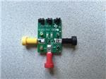
Figure 2. Jumper Configuration
3
Board Layout
Figure 3 and Figure 4 show the board layout for the LM2775EVM. The EVM offers capacitors and jumpers
to enable the device and to configure it as desired.
SNVU469A – May 2015 – Revised June 2018
Submit Documentation Feedback
LM2775EVM User's Guide
Copyright © 2015–2018, Texas Instruments Incorporated
5
�Board Layout
www.ti.com
The LM2775 will dissipate power, especially during high current and high input voltage operation. The
EVM layout is designed to minimize temperature rise during operation.
NOTE: High frequency switching noise at the output can be minimized by adding a 0.1-µF ceramic
capacitor close to the output terminals (VOUT)
Figure 3. Top Assembly Layer
6
LM2775EVM User's Guide
SNVU469A – May 2015 – Revised June 2018
Submit Documentation Feedback
Copyright © 2015–2018, Texas Instruments Incorporated
�Board Layout
www.ti.com
Figure 4. Bottom Assembly Layer (UNMIRRORED)
SNVU469A – May 2015 – Revised June 2018
Submit Documentation Feedback
LM2775EVM User's Guide
Copyright © 2015–2018, Texas Instruments Incorporated
7
�Schematic
4
www.ti.com
Schematic
Figure 5. LM2775EVM Schematic
8
LM2775EVM User's Guide
SNVU469A – May 2015 – Revised June 2018
Submit Documentation Feedback
Copyright © 2015–2018, Texas Instruments Incorporated
�Bill of Materials
www.ti.com
5
Bill of Materials
DESIGNATOR
DESCRIPTION
MANUFACTURER
PART NUMBER
QUANTIT
Y
U1
Switched Capacitor 5 V Boost Converter, DSG0008A
Texas Instruments
LM2775DSG
1
!PCB1
Printed Circuit Board
Any
SV601144
1
C1, C2
CAP, CERM, 10 µF, 10 V, +/- 20%, X5R, 0402
Samsung
CL05A106MP5NUNC
2
C3
CAP, CERM, 1 µF, 35 V, +/- 10%, JB, 0402
TDK
C1005JB1V105K050BC
1
C4
CAP, CERM, 10 µF, 10 V, +/- 20%, X5R, 0603
TDK
C1608X5R1A106M
1
J1, J2, J3
Header, 100mil, 3x1, Gold, TH
Samtec
TSW-103-07-G-S
3
J4
Standard Banana Jack, Insulated, Red
Keystone
6091
1
J5
BANANA JACK, 15A, Insulated, Nylon,Yellow
Emerson Network Power
108-0907-001
1
J6
Standard Banana Jack, Insulated, Black
Keystone
6092
1
SH-J1, SH-J2, SH-J3
Shunt, 100mil, Gold plated, Black
3M
969102-0000-DA
3
TP1
Test Point, Multipurpose, Red, TH
Keystone
5010
1
TP2
Test Point, Multipurpose, Yellow, TH
Keystone
5014
1
TP5, TP6
Test Point, Multipurpose, Black, TH
Keystone
5011
2
space
space
space
space
Revision History
NOTE: Page numbers for previous revisions may differ from page numbers in the current version.
Changes from Original (May 2015) to A Revision ........................................................................................................... Page
•
Added a note "High frequency switching noise at the output can be minimized by adding a 0.1-µF ceramic capacitor close
to the output terminals" ................................................................................................................... 6
SNVU469A – May 2015 – Revised June 2018
Submit Documentation Feedback
Revision History
Copyright © 2015–2018, Texas Instruments Incorporated
9
�IMPORTANT NOTICE FOR TI DESIGN INFORMATION AND RESOURCES
Texas Instruments Incorporated (‘TI”) technical, application or other design advice, services or information, including, but not limited to,
reference designs and materials relating to evaluation modules, (collectively, “TI Resources”) are intended to assist designers who are
developing applications that incorporate TI products; by downloading, accessing or using any particular TI Resource in any way, you
(individually or, if you are acting on behalf of a company, your company) agree to use it solely for this purpose and subject to the terms of
this Notice.
TI’s provision of TI Resources does not expand or otherwise alter TI’s applicable published warranties or warranty disclaimers for TI
products, and no additional obligations or liabilities arise from TI providing such TI Resources. TI reserves the right to make corrections,
enhancements, improvements and other changes to its TI Resources.
You understand and agree that you remain responsible for using your independent analysis, evaluation and judgment in designing your
applications and that you have full and exclusive responsibility to assure the safety of your applications and compliance of your applications
(and of all TI products used in or for your applications) with all applicable regulations, laws and other applicable requirements. You
represent that, with respect to your applications, you have all the necessary expertise to create and implement safeguards that (1)
anticipate dangerous consequences of failures, (2) monitor failures and their consequences, and (3) lessen the likelihood of failures that
might cause harm and take appropriate actions. You agree that prior to using or distributing any applications that include TI products, you
will thoroughly test such applications and the functionality of such TI products as used in such applications. TI has not conducted any
testing other than that specifically described in the published documentation for a particular TI Resource.
You are authorized to use, copy and modify any individual TI Resource only in connection with the development of applications that include
the TI product(s) identified in such TI Resource. NO OTHER LICENSE, EXPRESS OR IMPLIED, BY ESTOPPEL OR OTHERWISE TO
ANY OTHER TI INTELLECTUAL PROPERTY RIGHT, AND NO LICENSE TO ANY TECHNOLOGY OR INTELLECTUAL PROPERTY
RIGHT OF TI OR ANY THIRD PARTY IS GRANTED HEREIN, including but not limited to any patent right, copyright, mask work right, or
other intellectual property right relating to any combination, machine, or process in which TI products or services are used. Information
regarding or referencing third-party products or services does not constitute a license to use such products or services, or a warranty or
endorsement thereof. Use of TI Resources may require a license from a third party under the patents or other intellectual property of the
third party, or a license from TI under the patents or other intellectual property of TI.
TI RESOURCES ARE PROVIDED “AS IS” AND WITH ALL FAULTS. TI DISCLAIMS ALL OTHER WARRANTIES OR
REPRESENTATIONS, EXPRESS OR IMPLIED, REGARDING TI RESOURCES OR USE THEREOF, INCLUDING BUT NOT LIMITED TO
ACCURACY OR COMPLETENESS, TITLE, ANY EPIDEMIC FAILURE WARRANTY AND ANY IMPLIED WARRANTIES OF
MERCHANTABILITY, FITNESS FOR A PARTICULAR PURPOSE, AND NON-INFRINGEMENT OF ANY THIRD PARTY INTELLECTUAL
PROPERTY RIGHTS.
TI SHALL NOT BE LIABLE FOR AND SHALL NOT DEFEND OR INDEMNIFY YOU AGAINST ANY CLAIM, INCLUDING BUT NOT
LIMITED TO ANY INFRINGEMENT CLAIM THAT RELATES TO OR IS BASED ON ANY COMBINATION OF PRODUCTS EVEN IF
DESCRIBED IN TI RESOURCES OR OTHERWISE. IN NO EVENT SHALL TI BE LIABLE FOR ANY ACTUAL, DIRECT, SPECIAL,
COLLATERAL, INDIRECT, PUNITIVE, INCIDENTAL, CONSEQUENTIAL OR EXEMPLARY DAMAGES IN CONNECTION WITH OR
ARISING OUT OF TI RESOURCES OR USE THEREOF, AND REGARDLESS OF WHETHER TI HAS BEEN ADVISED OF THE
POSSIBILITY OF SUCH DAMAGES.
You agree to fully indemnify TI and its representatives against any damages, costs, losses, and/or liabilities arising out of your noncompliance with the terms and provisions of this Notice.
This Notice applies to TI Resources. Additional terms apply to the use and purchase of certain types of materials, TI products and services.
These include; without limitation, TI’s standard terms for semiconductor products http://www.ti.com/sc/docs/stdterms.htm), evaluation
modules, and samples (http://www.ti.com/sc/docs/sampterms.htm).
Mailing Address: Texas Instruments, Post Office Box 655303, Dallas, Texas 75265
Copyright © 2018, Texas Instruments Incorporated
�