LM2796
www.ti.com
SNVS273A – MAY 2004 – REVISED MAY 2013
LM2796 Dual-Display White LED Driver with 3/2x Switched Capacitor Boost
Check for Samples: LM2796
FEATURES
DESCRIPTION
•
•
The LM2796 is a charge-pump based white-LED
driver that is ideal for mobile phone display
backlighting. It can drive up to 7 LEDs in parallel with
up to 20mA through each LED. Regulated internal
current sources deliver excellent current and
brightness matching in all LEDs. The LED-driver
current sources are split into two independently
controlled groups. The primary group (4 LEDs) can
be used to backlight the main phone display. The
second group (3 LEDs) can be used to backlight a
secondary display or to provide other lighting features
(keypad LEDs, for example). Brightness of the two
groups can be adjusted independently with pulsewidth modulated (PWM) digital signals.
1
2
•
•
•
•
•
Drives up to 7 LEDs with up to 20mA Each
LEDs Controlled in 2 Distinct Groups, for
Backlighting 2 Displays (Main LCD and SubLCD)
Excellent Current and Brightness Matching
High-Efficiency 3/2x Charge Pump
Extended Li-Ion Input: 2.7V to 5.5V
PWM Brightness Control: 100Hz - 1kHz
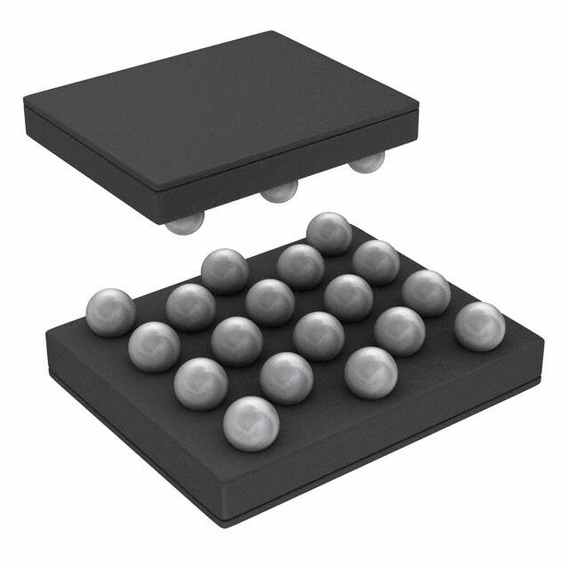
18-bump Thin DSBGA Package: (2.1mm x
2.4mm x 0.6mm)
APPLICATIONS
•
•
•
•
The LM2796 works off an extended Li-Ion input
voltage range (2.7V to 5.5V). Voltage boost is
achieved with a high-efficiency 3/2×-gain charge
pump.
Mobile Phone Display Lighting
Mobile Phone Keypad Lighting
PDAs
General LED Lighting
The LM2796 is available in TI’s chip-scale 18-bump
DSBGA package.
Typical Application Circuit
C1
1 PF
VIN
2.7V to 5.5V
C1+
VIN
C2
1 PF
C1-
C2+
Master Enable and Current Source Enables for
ON/OFF Control and PWM Dimming
C2-
EN
ENA
3/2× Charge Pump
(1× when VIN > 4.7V)
ENB
POUT
LM2796
CIN
1 PF*
CPOUT
1 PF*
ISET
GND
D1A
Capacitors: TDK C1608X5R1A105K,
or equivalent
D2A
D3A
D4A
D1B
D2B
D3B
RSET
*If total LED current is above 80 mA, as can occur
when all 7 outputs are ON simultaneously, 2.2 PF
capacitors are recommended for CIN and CPOUT.
1
2
Please be aware that an important notice concerning availability, standard warranty, and use in critical applications of
Texas Instruments semiconductor products and disclaimers thereto appears at the end of this data sheet.
All trademarks are the property of their respective owners.
PRODUCTION DATA information is current as of publication date.
Products conform to specifications per the terms of the Texas
Instruments standard warranty. Production processing does not
necessarily include testing of all parameters.
Copyright © 2004–2013, Texas Instruments Incorporated
�LM2796
SNVS273A – MAY 2004 – REVISED MAY 2013
www.ti.com
Connection Diagram
7
6
5
4
3
2
1
7
6
5
4
3
2
1
A
B
C
D
E
E
Top View
D
C
B
A
Bottom View
Figure 1. 18-Bump Thin DSBGA Package, Large Bump
Package Number YZR0018
PIN DESCRIPTION
Pin #s
Pin Names
C1
VIN
Pin Descriptions
Input voltage. Input range: 2.7V to 5.5V.
D2
GND
Ground
A3
POUT
Charge pump output. Approximately 1.5×VIN
A1, B2, A5, E1
C1+, C1-, C2+, C2-
A7
EN
D6, E5, D4, E3
Flying capacitor connections.
Enable pin. Logic input. High = normal operation, Low = shutdown (charge pump and all
current sources OFF).
D1A, D2A, D3A, D4A LED Outputs - Group A
C5, B4, C3
D1B, D2B, D3B
LED Outputs - Group B
B6
EN-A
Enable for Group-A LEDs (current outputs). Logic input.
High = Group-A LEDs ON. Low = Group A LEDs OFF.
Pulsing this pin with a PWM signal (100Hz-1kHz) can be used to dim LEDs.
E7
EN-B
Enable for Group-B LEDs (current outputs). Logic input.
High = Group-B LEDs ON. Low = Group B LEDs OFF.
Pulsing this pin with a PWM signal (100Hz-1kHz) can be used to dim LEDs.
C7
ISET
Placing a resistor (RSET) between this pin and GND sets the LED current for all LEDs. LED
Current = 100 × (1.25V ÷ RSET).
These devices have limited built-in ESD protection. The leads should be shorted together or the device placed in conductive foam
during storage or handling to prevent electrostatic damage to the MOS gates.
2
Submit Documentation Feedback
Copyright © 2004–2013, Texas Instruments Incorporated
Product Folder Links: LM2796
�LM2796
www.ti.com
SNVS273A – MAY 2004 – REVISED MAY 2013
ABSOLUTE MAXIMUM RATINGS (1) (2) (3)
VIN pin voltage
-0.3V to 7.1V
EN, ENA, ENB pin voltages
-0.3V to (VIN+0.3V)w/ 5.6V
max
Continuous Power Dissipation (4)
Internally Limited
Junction Temperature (TJ-MAX)
150ºC
Storage Temperature Range
-65ºC to +150º C
Maximum Lead Temperature (Soldering, 10 sec.)
ESD Rating
(1)
(2)
(3)
(4)
(5)
(5)
265ºC
Human Body Model
2.0kV
Machine Model
200V
Absolute Maximum Ratings indicate limits beyond which damage to the component may occur. Operating Ratings are conditions under
which operation of the device is specified. Operating Ratings do not imply specified performance limits. For specified performance limits
and associated test conditions, see the Electrical Characteristics tables.
All voltages are with respect to the potential at the GND pin.
If Military/Aerospace specified devices are required, please contact the Texas Instruments Sales Office/ Distributors for availability and
specifications.
Internal thermal shutdown circuitry protects the device from permanent damage. Thermal shutdown engages at TJ = 160°C (typ.) and
disengages at TJ = 120°C (typ.). The thermal shutdown function is specified by design.
The Human body model is a 100pF capacitor discharged through a 1.5k resistor into each pin. The machine model is a 200pF capacitor
discharged directly into each pin. MIL-STD-883 3015.7
OPERATING RATING (1) (2)
Input Voltage Range
2.7V to 5.5V
Junction Temperature (TJ) Range
-30°C to +125°C
Ambient Temperature (TA) Range (3)
(1)
(2)
(3)
-30°C to +85°C
Absolute Maximum Ratings indicate limits beyond which damage to the component may occur. Operating Ratings are conditions under
which operation of the device is specified. Operating Ratings do not imply specified performance limits. For specified performance limits
and associated test conditions, see the Electrical Characteristics tables.
All voltages are with respect to the potential at the GND pin.
In applications where high power dissipation and/or poor package thermal resistance is present, the maximum ambient temperature may
have to be derated. Maximum ambient temperature (TA-MAX) is dependent on the maximum operating junction temperature (TJ-MAX-OP =
125°C), the maximum power dissipation of the device in the application (PD-MAX), and the junction-to ambient thermal resistance of the
part/package in the application (θJA), as given by the following equation: TA-MAX = TJ-MAX-OP – (θJA × PD-MAX).
THERMAL PROPERTIES
Juntion-to-Ambient Thermal Resistance (θJA) (1)
(1)
100°C/W
Junction-to-ambient thermal resistance is highly dependent on application and board layout. In applications where high maximum power
dissipation exists, special care must be paid to thermal dissipation issues in board design.
Submit Documentation Feedback
Copyright © 2004–2013, Texas Instruments Incorporated
Product Folder Links: LM2796
3
�LM2796
SNVS273A – MAY 2004 – REVISED MAY 2013
www.ti.com
ELECTRICAL CHARACTERISTICS (1) (2)
Limits in standard typeface and typical values apply for TJ = 25ºC. Limits in boldface type apply over the full operating
junction temperature range (-30°C ≤ TJ ≤ +85°C) . Unless otherwise specified: VIN = 3.6V; VDxx = 3.6V; V(EN) = 2.0V; Group A
and Group B LEDs not ON simultaneously (3) (ENA = VIN and ENB = GND, or ENA = GND and ENB = VIN); RSET = 8.35kΩ;
CIN, C1, C2, and CPOUT = 1µF (4).
Symbol
Parameter
Condition
3.0V ≤ VIN ≤ 4.2V, and VIN = 5.5V
2.5V ≤ VDxx ≤ 3.8V;
RSET = 8.35kΩ
IDxx
Output Current Regulation
Min
Typ
Max
Units
13.8
(-8%)
15
16.2
(+8%)
mA
(%)
3.0V ≤ VIN ≤ 5.5V;
2.5V ≤ VDxx ≤ 3.6V;
RSET = 6.25kΩ
20
mA
3.0V ≤ VIN ≤ 5.5V;
2.5V ≤ VDxx ≤ 3.9V;
RSET = 12.5kΩ
10
mA
2.7V ≤ VIN ≤ 3.0V;
2.5V ≤ VDxx ≤ 3.3V;
RSET = 8.35kΩ
15
mA
ENA and ENB ON (all 7 IDX outputs active), VIN =
3.0V, CIN = COUT = 2.2µF
15
mA
1
%
IDxx-MATCH
Current Matching Between Any
Two Group A Outputs or Group B
Outputs
VIN = 3.0V (5)
IQ
Quiescent Supply Current
2.7V ≤ VIN ≤ 4.2V;
No Load Current,
EN = ON, ENA = ENB = OFF
ISD
Shutdown Supply Current
2.7V ≤ VIN ≤ 5.5V, EN = OFF
VSET
ISET Pin Voltage
2.7V ≤ VIN ≤ 5.5V
IDxx/ISET
Output Current to Current Set
Ratio
ROUT
Charge Pump Output
Resistance (6)
VHR
IDxx = 95% X IDxx (nom)
RSET = 8.35kΩ
Current Source Headroom Voltage (IDxx (nom) ≈ 15mA)
Requirement (7)
IDxx = 95%X IDxx (nom)
RSET = 12.5kΩ
(IDxx (nom) ≈ 10mA)
3.5
6
mA
3
4.5
µA
1.25
V
100
VIN = 3.0V
Ω
2.7
320
mV
220
fSW
Switching Frequency
3.0V ≤ VIN ≤ 4.2V
tSTART
Start-up Time
IDx = 90% steady state
100
µs
1.5x to 1x Threshold
4.75
V
1.5x/1x
Charge pump gain cross-over:
Gain = 1.5 when VIN is below
threshold. Gain = 1 when VIN is
above threshold.
1x to 1.5x Threshold
4.55
V
325
500
675
kHz
Logic Pin Specifications: EN, ENA, ENB
VIL
(1)
(2)
(3)
(4)
(5)
(6)
(7)
4
Input Logic Low
2.7V ≤ VIN ≤ 5.5V
0
0.5
V
All voltages are with respect to the potential at the GND pin.
Min and Max limits are specified by design, test, or statistical analysis. Typical numbers are not specified, but do represent the most
likely norm.
If both LED groups are to be ON simultaneously, the maximum VDxx voltage may need to be derated, depending on minimum input
voltage conditions. Refer to the "MAXIMUM OUTPUT CURRENT, MAXIMUM LED VOLTAGE, MINIMUM INPUT VOLTAGE" section.
CIN, COUT, C1, and C2 : Low-ESR Surface-Mount Ceramic Capacitors (MLCCs) used in setting electrical characteristics
For the two groups of outputs on a part (Group A and Group B), the following are determined: the maximum output current in the group
(MAX), the minimum output current in the group (MIN), and the average output current of the group (AVG). For each group, two
matching numbers are calculated: (MAX-AVG)/AVG and (AVG-MIN)/AVG. The largest number of the two (worst case) is considered the
matching figure for the group. The matching figure for a given part is considered to be the highest matching figure of the two groups.
The typical specification provided is the most likely norm of the matching figure for all parts.
Output resistance (ROUT) models all voltage losses in the charge pump. ROUT can be used to estimate the voltage at the charge pump
output (POUT): VPout = (1.5 × VIN) – (ROUT × IOUT). In the equation, IOUT is the total output current: the sum of all active Dxx output
currents and all current drawn from POUT. The equation applies when the charge pump is operating with a gain of 3/2 (VIN ≤ 4.75V typ.).
Headroom voltage: VHR = VPout – VDxx . If headroom voltage requirement is not met, LED current regulation will be compromised.
Submit Documentation Feedback
Copyright © 2004–2013, Texas Instruments Incorporated
Product Folder Links: LM2796
�LM2796
www.ti.com
SNVS273A – MAY 2004 – REVISED MAY 2013
ELECTRICAL CHARACTERISTICS(1)(2) (continued)
Limits in standard typeface and typical values apply for TJ = 25ºC. Limits in boldface type apply over the full operating
junction temperature range (-30°C ≤ TJ ≤ +85°C) . Unless otherwise specified: VIN = 3.6V; VDxx = 3.6V; V(EN) = 2.0V; Group A
and Group B LEDs not ON simultaneously(3) (ENA = VIN and ENB = GND, or ENA = GND and ENB = VIN); RSET = 8.35kΩ;
CIN, C1, C2, and CPOUT = 1µF(4).
Symbol
VIH
Input Logic High
ILEAK
(8)
Parameter
Input Leakage Current
Condition
2.7V ≤ VIN ≤ 5.5V
Min
Typ
1.1
VENx = 0V
0.1
VENx = 3V (8)
10
Max
Units
VIN
V
µA
There is a 300kΩ(typ.) pull-down resistor connected internally between each enable pin (EN, ENA, ENB) and GND.
Submit Documentation Feedback
Copyright © 2004–2013, Texas Instruments Incorporated
Product Folder Links: LM2796
5
�LM2796
SNVS273A – MAY 2004 – REVISED MAY 2013
www.ti.com
TYPICAL PERFORMANCE CHARACTERISTICS
Unless otherwise specified: VIN = 3.6V; VDXX = 3.6V; V(EN) = 2.0V; V(ENA) = 2.0V; V(ENB) = 0V; RSET = 8.3 kΩ; CIN, C1, C2,
and CPOUT = 1 µF.
LED Current
vs.
Input Voltage
LED Current
vs.
RSET Resistance
30
25
15.5
IDXX - LED CURRENT (mA)
IDXX - LED CURRENT (mA)
16.0
TA = 25°C, T A = -30°C
15.0
TA = 85°C
14.5
20
15
10
5
14.0
2.8 3.1 3.4 3.7 4.0 4.3 4.6 4.9 5.2 5.5
0
0
20
VIN - INPUT VOLTAGE (V)
80
100
Figure 2.
Figure 3.
LED Current
vs.
PWM Duty Cycle,
PWM Applied to ENA and/or ENB
Charge Pump Output Resistance
vs. Ambient Temperature
120
ROUT - OUTPUT RESISTANCE (:)
4.0
14
IDXX - LED CURRENT (mA)
60
RSET RESISTANCE (k:)
16
12
10
8
6
4
2
0
0
20
40
60
80
100
3.6
VIN = 2.7V
VIN = 3.0V
3.2
2.8
VIN = 3.3V
2.4
2.0
-30
VIN = 3.6V
0
30
60
90
120
TA - AMBIENT TEMPERATURE (ºC)
PWM DUTY CYCLE (%)
Figure 4.
6
40
Figure 5.
Submit Documentation Feedback
Copyright © 2004–2013, Texas Instruments Incorporated
Product Folder Links: LM2796
�LM2796
www.ti.com
SNVS273A – MAY 2004 – REVISED MAY 2013
CIRCUIT DESCRIPTION
OVERVIEW
The LM2796 is primarily intended for Lithium-Ion battery driven white-LED drive applications, and is well suited to
drive white LEDs that are used for backlighting small-format displays. The part has seven matched constantcurrent outputs, each capable of driving up to 20mA (or more) through white LEDs. The well-matched current
sources ensure the current through all the LEDs is virtually identical. This keeps brightness of all LEDs matched
to near perfection so that they can provide a consistent backlight over the entire display.
The core of the LM2796 is a 1.5x/1x dual-mode charge pump. The input of the charge pump is connected to the
VIN pin. The recommended input voltage range of the LM2796 is 2.7V to 5.5V. The output of the charge pump is
the POUT pin ( “Pump OUTput”). The output voltage of the charge pump is unregulated and varies with input
voltage and load current.
The charge pump operates in the 1.5x mode when the input voltage is below 4.75V (typ.). In this mode, the
input-to-output voltage gain of the charge pump is 1.5, and the voltage at the output of the charge pump will be
approximately 1.5x the input voltage (V(POUT) ≈ 1.5 * VIN ). When in the 1.5x mode, the charge pump provides
the voltage boost that is required to drive white LEDs from a Li-Ion battery. (White LEDs typically have a forward
voltage in the range of 3.3V to 4.0V. A Li-Ion battery typically is not considered to be fully discharged until the
battery voltage falls to 3.0V (approx.) )
The charge pump operates in the 1x mode when the input voltage is above 4.75V (typ.). In these conditions,
voltage boost is not required to drive the LEDs, so the charge pump merely passes the input voltage to POUT
(V(POUT) ≈ VIN). This reduces the input current and the power dissipation of the LM2796 when the input voltage is
high.
The matched current outputs are generated with a precision current mirror that is biased off the charge pump
output. Matched currents are ensured with the use of tightly matched internal devices and internal mismatch
cancellation circuitry. Top-side current drive allows LEDs to be connected between each current output and
GND, simplifying PWB routing and connectivity.
There are seven regulated current outputs. These seven outputs are split into two groups, a group of 4 outputs
and a group of 3 outputs. There is an ON/OFF control pin for each group.
The DC current through the LEDs is programmed with an external resistor. Changing currents on-the-fly can be
achieved with the use of digital pulse (PWM) signals.
ENABLE PINS: EN, ENA, ENB
The LM2796 has 3 enable pins. All three are active-high logic (HIGH = ON). There are internal pull-down
resistors (300kΩ typ.) that are connected internally between each of the enable pins and GND.
The EN pin is the master enable pin for the part. When voltage on this pin is low (1.1V), the part is active. The charge pump is ON, and it is
possible to turn on the output currents to drive the LEDs.
ENA and ENB are used to turn the output currents ON and OFF. ENA activates/deactivates the four group-A
outputs (D1A-D4A). ENB activates/deactivates the three group-B outputs (D1B-D3B).
SETTING LED CURRENTS
The output currents of the LM2796 can be set to a desired value simply by connecting an appropriately sized
resistor (RSET) between the ISET pin of the LM2796 and GND. The output currents (LED currents) are proportional
to the current that flows out of the ISET pin. The output currents are a factor of 100 greater than the ISET current.
The feedback loop of an internal amplifier sets the voltage of the ISET pin to 1.25V (typ.). Placing a resistor
between ISET and GND programs the ISET current, and thus the LED currents. The statements above are
simplified in the equations below:
IDxx = 100 ×(VSET / RSET)
RSET = 100 × (1.25V / IDxx)
(1)
(2)
Submit Documentation Feedback
Copyright © 2004–2013, Texas Instruments Incorporated
Product Folder Links: LM2796
7
�LM2796
SNVS273A – MAY 2004 – REVISED MAY 2013
www.ti.com
Maximum Output Current, Maximum LED Voltage, Minimum Input Voltage
The LM2796 can drive 7 LEDs at 15mA each from an input voltage as low as 3.0V, so long as the LEDs have a
forward voltage of 3.6V or less (room temperature).
The statement above is a simple example of the LED drive capabilities of the LM2796. The statement contains
the key application parameters that are required to validate an LED-drive design using the LM2796: LED current
(ILED), number of active LEDs (N), LED forward voltage (VLED), and minimum input voltage (VIN-MIN).
The equation below can be used to estimate the total output current capability of the LM2796:
ILED_MAX = ((1.5 x VIN) - VLED) / ((N x ROUT) + kHR)
ILED_MAX = ((1.5 x VIN ) - VLED) / ((N x 2.7Ω) + 22mV/mA)
(3)
ROUT – Output resistance. This parameter models the internal losses of the charge pump that result in voltage
droop at the pump output POUT. Since the magnitude of the voltage droop is proportional to the total output
current of the charge pump, the loss parameter is modeled as a resistance. The output resistance of the LM2796
is typically 2.7Ω (VIN = 3.0V, TA = 25°C). In equation form:
VPOUT = 1.5×VIN – N×ILED×ROUT
(4)
kHR – Headroom constant. This parameter models the minimum voltage required to be present across the current
sources for them to regulate properly. This minimum voltage is proportional to the programmed LED current, so
the constant has units of mV/mA. The typical kHR of the LM2796 is 22mV/mA. In equation form:
(VPOUT – VLED) > kHR×ILED
(5)
The "ILED-MAX" equation (Equation 3) is obtained from combining the ROUT equation (Equation 4) with the kHR
equation (Equation 5) and solving for ILED. Maximum LED current is highly dependent on minimum input voltage
and LED forward voltage. Output current capability can be increased by raising the minimum input voltage of the
application, or by selecting an LED with a lower forward voltage. Excessive power dissipation may also limit
output current capability of an application.
Soft Start
The LM2796 contains internal soft-start circuitry to limit input inrush currents when the part is enabled. Soft start
is implemented internally with a controlled turn-on of the internal voltage reference. During soft start, the current
through the LED outputs rise at the rate of the reference voltage ramp. Due to the soft-start circuitry, turn-on time
of the LM2796 is approximately 100µs (typ.).
Thermal Protection
Internal thermal protection circuitry disables the LM2796 when the junction temperature exceeds 160°C (typ.).
This feature protects the device from being damaged by high die temperatures that might otherwise result from
excessive power dissipation. The device will recover and operate normally when the junction temperature falls
below 120°C (typ.). It is important that the board layout provides good thermal conduction. This will help to keep
the junction temperature within specified operating ratings.
8
Submit Documentation Feedback
Copyright © 2004–2013, Texas Instruments Incorporated
Product Folder Links: LM2796
�LM2796
www.ti.com
SNVS273A – MAY 2004 – REVISED MAY 2013
APPLICATIONS INFORMATION
ADJUSTING LED BRIGHTNESS (PWM control)
Perceived LED brightness can be adjusted using a PWM control signal to turn the LM2796 current sources ON
and OFF at a rate faster than perceptible by the eye. When this is done, the total brightness perceived is
proportional to the duty cycle (D) of the PWM signal (D = the percentage of time that the LED is on in every
PWM cycle). A simple example: if the LEDs are driven at 15mA each with a PWM signal that has a 50% duty
cycle, perceived LED brightness will be about half as bright as compared to when the LEDs are driven
continuously with 15mA. A PWM signal thus provides brightness (dimming) control for the solution.
The minimum recommended PWM frequency is 100Hz. Frequencies below this may be visibly noticeable as
flicker or blinking. The maximum recommended PWM frequency is 1kHz. Frequencies above this may cause
interference with internal current driver circuitry.
The preferred method for applying a PWM signal to adjust brightness is to keep the master EN voltage ON
continuously and to apply the PWM signal(s) to the current source enable pin(s): ENA and/or ENB. The benefit of
this type of connection can be best understood with a contrary example. When a PWM signal is connected to the
master enable (EN) pin, the charge pump repeatedly turns on and off. Every time the charge pump turns on,
there is an inrush of current as capacitances, both internal and external, are recharged. This inrush current
results in a current and voltage spike at the input of the part. By only applying the PWM signal to ENA/ENB, the
charge pump stays on continuously and much lower input noise results.
In cases where a PWM signal must be connected to the EN pin, measures can be taken to reduce the
magnitude of the charge-pump turn-on voltage spikes. More input capacitance, series resistors and/or ferrite
beads may provide benefits.
If the current and voltage spikes can be tolerated, connecting the PWM signal to the EN pin does provide a
benefit: lower supply current when the PWM signal is active. When the PWM signal is low, the LM2796 will be
shutdown and input current will only be a few micro-amps. This results in a lower time-averaged input current
than the prior suggestion, where EN is kept on continuously.
CAPACITOR SELECTION
The LM2796 requires 4 external capacitors for proper operation. Surface-mount multi-layer ceramic capacitors
are recommended. These capacitors are small, inexpensive and have very low equivalent series resistance (ESR