User's Guide
SNVA345B – November 2008 – Revised April 2013
AN-1844 LM2833Z MSOP-PowerPAD Demo Board
1
Introduction
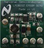
The LM2833Z MSOP-PowerPAD demo board is designed to demonstrate the capabilities of the LM2833Z
3MHz switching regulator in an MSOP PowerPAD-10 package.
The demo board is configured to provide an output of 1.2V at up to 3A from an input voltage range of 3V
to 5.5V. The board is thermally optimized with the small solution size of 1.2" X 1.1", shown in the demo
board schematic in Figure 1. The output voltage can be configured to a different value by changing the
ratio between R1 and R2 according to the following equation:
R1 = R2 x (VOUT / VFB - 1)
(1)
The feedback voltage VFB is regulated at 0.60V typically.
The board has C5 reserved for two purposes given different application scenarios. First, at high VOUT
applications, the control loop bandwidth is not as large as at low VOUT. Adding C5 at high VOUT can
significantly improve the load step response by boosting the loop bandwidth without significantly
compromising phase margin. Secondly, it also helps to minimize output voltage overshoot during sluggish
startup, short circuit release, and recovery from thermal shutdown, since it creates a feed-forward path
between VOUT and VFB, thus speeding up Gm-amplifier recovery. In practice, for a few kΩ of voltage
divider bottom resistor R2, a 47nF ceramic capacitor is usually a good choice for C5. Note for applications
where VOUT is close to VFB, since R1 is small, the effectiveness of adding C5 becomes decreasingly
appreciable. Therefore, other measures need to be taken to achieve the desired performance. For
example, to minimize output overshoot during slow startup at high VOUT, an alternative approach is to
apply a separate signal at the EN terminal after VIN is fully established.
Another component which is not populated on the board is C4, which is reserved for applications where a
large output capacitor is desired.
Table 1 lists the bill of materials of this demo board. The measured performance characteristics and layout
of this board are also included below.
2
Powering up the Board
Powering up the LM2833Z MSOP-PowerPAD demo board is a single-step procedure, simply by applying a
DC voltage of 3V to 5.5V to VIN and GND terminals. By default, VINC is connected to VIN through a low
pass filter to remove any high frequency noise present at the input. EN is connected to VINC through a
100kΩ resistor. A separate logic signal at the EN terminal can be used, if startup and shutdown need to
be controlled. A load can be connected between VOUT and GND terminals before or after the board is
powered up. At VOUT of 1.2V, the internal soft-start circuit can bring up VOUT smoothly regardless of
load or input voltage.
The LM2833Z is designed to skip some pulses at very light loads to maintain output voltage regulation.
Depending on load levels, the circuit may operate in either discontinuous or continuous conduction mode.
All trademarks are the property of their respective owners.
SNVA345B – November 2008 – Revised April 2013
Submit Documentation Feedback
AN-1844 LM2833Z MSOP-PowerPAD Demo Board
Copyright © 2008–2013, Texas Instruments Incorporated
1
�Typical Performance Characteristics
www.ti.com
Figure 1. LM2833Z MSOP-PowerPAD Demo Board Schematic
3
Typical Performance Characteristics
Efficiency
vs
Load Current
2
AN-1844 LM2833Z MSOP-PowerPAD Demo Board
Efficiency
vs
Load Current
SNVA345B – November 2008 – Revised April 2013
Submit Documentation Feedback
Copyright © 2008–2013, Texas Instruments Incorporated
�Typical Performance Characteristics
www.ti.com
Load Regulation
Startup (VIN Slew Rate = 0.2V/µs )
Startup (VIN Slew Rate = 1V/ms )
Steady-state (CCM Mode)
Steady-state (DCM Mode)
Steady-state (Pulse Skipping)
SNVA345B – November 2008 – Revised April 2013
Submit Documentation Feedback
AN-1844 LM2833Z MSOP-PowerPAD Demo Board
Copyright © 2008–2013, Texas Instruments Incorporated
3
�Typical Performance Characteristics
4
www.ti.com
Load Transient (Slew Rate = 0.1A/µs)
(C5 not installed)
Load Transient (Slew Rate = 0.1A/µs)
(C5 = 47nF)
Line Transient
Loop Gain
AN-1844 LM2833Z MSOP-PowerPAD Demo Board
SNVA345B – November 2008 – Revised April 2013
Submit Documentation Feedback
Copyright © 2008–2013, Texas Instruments Incorporated
�Layout
www.ti.com
4
Layout
Figure 2. Top Layer and Top Overlay
Figure 3. Internal Plane 1 (GND)
SNVA345B – November 2008 – Revised April 2013
Submit Documentation Feedback
AN-1844 LM2833Z MSOP-PowerPAD Demo Board
Copyright © 2008–2013, Texas Instruments Incorporated
5
�Layout
www.ti.com
Figure 4. Bottom Layer
Figure 5. Internal Plane 2 (VIN)
6
AN-1844 LM2833Z MSOP-PowerPAD Demo Board
SNVA345B – November 2008 – Revised April 2013
Submit Documentation Feedback
Copyright © 2008–2013, Texas Instruments Incorporated
�Bill of Materials
www.ti.com
5
Bill of Materials
Table 1. Bill of Materials
Part ID
Part Value
Part Number
Manufacturer
U1
L1
3MHz 3.0A buck regulator, MSOP PowerPAD-10
LM2833
Texas Instruments
1.0µH, 4A, 5x5x2mm3
NP04SZB1R0N
Taiyo Yuden
C1
22µF, 6.3V, X5R, 1206
C3216X5R0J226MT
TDK
C2
0.22µF, 10V, X7R, 0805
GRM216R71A224KC01D
Murata
C3
47µF, 6.3V, X5R, 1206
JMK316BJ476ML-T
Taiyo Yuden
C4
Open
C5
Open
D1
Schottky, 30V, 3A, 3-4E1A
CMS01
Toshiba
R1
2.00kΩ, 1%, 1/8W, 0805
CRCW08052K00FKEA
Vishay
R2
2.00kΩ, 1%, 1/8W, 0805
CRCW08052K00FKEA
Vishay
R3
10.0Ω, 1%, 1/8W, 0805
CRCW080510R0FKEA
Vishay
R4
100kΩ, 1%, 1/8W, 0805
CRCW0805100KFKEA
Vishay
SNVA345B – November 2008 – Revised April 2013
Submit Documentation Feedback
AN-1844 LM2833Z MSOP-PowerPAD Demo Board
Copyright © 2008–2013, Texas Instruments Incorporated
7
�IMPORTANT NOTICE
Texas Instruments Incorporated and its subsidiaries (TI) reserve the right to make corrections, enhancements, improvements and other
changes to its semiconductor products and services per JESD46, latest issue, and to discontinue any product or service per JESD48, latest
issue. Buyers should obtain the latest relevant information before placing orders and should verify that such information is current and
complete. All semiconductor products (also referred to herein as “components”) are sold subject to TI’s terms and conditions of sale
supplied at the time of order acknowledgment.
TI warrants performance of its components to the specifications applicable at the time of sale, in accordance with the warranty in TI’s terms
and conditions of sale of semiconductor products. Testing and other quality control techniques are used to the extent TI deems necessary
to support this warranty. Except where mandated by applicable law, testing of all parameters of each component is not necessarily
performed.
TI assumes no liability for applications assistance or the design of Buyers’ products. Buyers are responsible for their products and
applications using TI components. To minimize the risks associated with Buyers’ products and applications, Buyers should provide
adequate design and operating safeguards.
TI does not warrant or represent that any license, either express or implied, is granted under any patent right, copyright, mask work right, or
other intellectual property right relating to any combination, machine, or process in which TI components or services are used. Information
published by TI regarding third-party products or services does not constitute a license to use such products or services or a warranty or
endorsement thereof. Use of such information may require a license from a third party under the patents or other intellectual property of the
third party, or a license from TI under the patents or other intellectual property of TI.
Reproduction of significant portions of TI information in TI data books or data sheets is permissible only if reproduction is without alteration
and is accompanied by all associated warranties, conditions, limitations, and notices. TI is not responsible or liable for such altered
documentation. Information of third parties may be subject to additional restrictions.
Resale of TI components or services with statements different from or beyond the parameters stated by TI for that component or service
voids all express and any implied warranties for the associated TI component or service and is an unfair and deceptive business practice.
TI is not responsible or liable for any such statements.
Buyer acknowledges and agrees that it is solely responsible for compliance with all legal, regulatory and safety-related requirements
concerning its products, and any use of TI components in its applications, notwithstanding any applications-related information or support
that may be provided by TI. Buyer represents and agrees that it has all the necessary expertise to create and implement safeguards which
anticipate dangerous consequences of failures, monitor failures and their consequences, lessen the likelihood of failures that might cause
harm and take appropriate remedial actions. Buyer will fully indemnify TI and its representatives against any damages arising out of the use
of any TI components in safety-critical applications.
In some cases, TI components may be promoted specifically to facilitate safety-related applications. With such components, TI’s goal is to
help enable customers to design and create their own end-product solutions that meet applicable functional safety standards and
requirements. Nonetheless, such components are subject to these terms.
No TI components are authorized for use in FDA Class III (or similar life-critical medical equipment) unless authorized officers of the parties
have executed a special agreement specifically governing such use.
Only those TI components which TI has specifically designated as military grade or “enhanced plastic” are designed and intended for use in
military/aerospace applications or environments. Buyer acknowledges and agrees that any military or aerospace use of TI components
which have not been so designated is solely at the Buyer's risk, and that Buyer is solely responsible for compliance with all legal and
regulatory requirements in connection with such use.
TI has specifically designated certain components as meeting ISO/TS16949 requirements, mainly for automotive use. In any case of use of
non-designated products, TI will not be responsible for any failure to meet ISO/TS16949.
Products
Applications
Audio
www.ti.com/audio
Automotive and Transportation
www.ti.com/automotive
Amplifiers
amplifier.ti.com
Communications and Telecom
www.ti.com/communications
Data Converters
dataconverter.ti.com
Computers and Peripherals
www.ti.com/computers
DLP® Products
www.dlp.com
Consumer Electronics
www.ti.com/consumer-apps
DSP
dsp.ti.com
Energy and Lighting
www.ti.com/energy
Clocks and Timers
www.ti.com/clocks
Industrial
www.ti.com/industrial
Interface
interface.ti.com
Medical
www.ti.com/medical
Logic
logic.ti.com
Security
www.ti.com/security
Power Mgmt
power.ti.com
Space, Avionics and Defense
www.ti.com/space-avionics-defense
Microcontrollers
microcontroller.ti.com
Video and Imaging
www.ti.com/video
RFID
www.ti-rfid.com
OMAP Applications Processors
www.ti.com/omap
TI E2E Community
e2e.ti.com
Wireless Connectivity
www.ti.com/wirelessconnectivity
Mailing Address: Texas Instruments, Post Office Box 655303, Dallas, Texas 75265
Copyright © 2013, Texas Instruments Incorporated
�