National Semiconductor
RD-164
Maurice Eaglin
October 2008
1.0 Design Specifications
Inputs
Output #1
VinMin=6V
Vout1=3.3V
VinMax=24V
Iout1=10A
2.0 Design Description
The LM3152-3.3 demonstration board is part of the PowerWise® family of SIMPLE SWITCHER® Controllers. It has
been designed to balance solution size and performance.
The Constant-On-Time (COT) Emulated Ripple Mode (ERM)
Control allows for the use of low ESR output capacitors and
therefore decreases the output voltage ripple while maintaining a fast transient response. There is no loop compensation
required for the COT architecture, as there is in voltage-mode
and current mode control architectures, which helps to facilitate the ease of design and fast transient response. The
demo board uses a 2-layer, 2 ounce copper PCB with all of
the components mounted on the top side. The LM3152-3.3
IC has a fixed output voltage of 3.3V and will operate over the
input voltage range of 6V to 24V at 10A load current. The
components within the dashed line of the board photo in Figure 3, represent the total design solution. The aluminum
electrolytic input capacitor Cin1 is used for input filter damping
when using long leads, which contributes to parasitic induc-
tance in the lab while using the demo board. Cin1 along with
the input/output posts and EN test point connector may not
be needed when the final circuit is integrated in the system
design.
3.0 Features
■
■
■
■
■
■
■
■
■
■
Easy To Use with Webench and Offline Design Tools
No Loop Compensation Required
Low Solution Component Count
Ultra-Fast Transient Response
Low Output Voltage Ripple (32mVpp)
3.3V Fixed Output Voltage
Optimized for 10A Average Load Current
95% Peak Efficiency
Constant-On-Time with Emulated Ripple Mode Control
500kHz Switching Frequency
LM3152-3.3 Demonstration Board
LM3152-3.3 Demonstration
Board
RD-164
© 2008 National Semiconductor Corporation
www.national.com
�D
C
B
GND
Cin1
100uF
2
PGND
SGND
1
Cin2
10uF
PGND
Cin3
10uF
Cen
Cbyp
0.1uF
SGND
Css
68n
EN
SGND
Css 6
EN 3
Vin 2
SS
EN
VIN
U1
LM3152MH-3.3
HG
VCC
BOOT
SW
LG
FB
SGND
11
1
12
10
13
4
SW
Cvcc
4.7uF
4
4
Cbst
PGND
0.47uF
LG
BST
Vcc
HG
PGND
M2
SW
M1
3
1.65uH
L1
2
3
Vo
Co1
150uF
PGND
Vo
GND
Co2
150uF
4
schematic6
Cf
4
Designed for: Public Release
Mod. Date: 8/14/2008
Project:
LM3152-3.3 Demo Boards
Sheet Title:
Sheet: 1 of 1
Size: Letter
Schematic: 870 600103
Rev: C
Assembly Variant: Variant name is not interpreted until output
File: LM3152-3p3 SO8.SchDoc
CADC:
http://www.national.com
Contact: http://www.national.com/support/
© Copyright, National Semiconductor, 2007
FIGURE 1. LM3152-3.3 Demo Board Schematic
PGND
2
National Semiconductor and/or its licensors do not warrant the accuracy or completeness of this
specification or any information contained therein. National and/or its licensors do not warrant that
this design will meet the specifications, will be suitable for your application or fit for any particular
purpose, or will operate in an implementation. National and/or its licensors do not warrant that the
design is production worthy. You should completely validate and test your design implementation
to confirm the system functionality for your application.
EP
Vin
PGND
14
SGND
SGND
SGND
SGND
5
7
8
9
5, 6, 7, 8
1, 2, 3
5, 6, 7, 8
www.national.com
1, 2, 3
A
1
D
C
B
A
RD-164
4.0 Schematic
�FIGURE 2. Bill of Materials
Designator
Manufacturer
Part Number
Value
U1
National Semiconductor
LM3152MH-3.3
Cbst
TDK
C2012X7R1C474K
0.47uF
Cbyp
TDK
C2012X7R1H104K
0.1uF
Cen
TDK
C1005X7R1H102K
1000pF
Cf
Cin1
Panasonic
EEV-FK1J101P
100uF
Cin2, Cin3
Taiyo Yuden
GMK325BJ106KN-T
10uF
Co1, Co2
Panasonic
EEF-UE0J151R
150uF
Css
AVX
0603YC683KAT2A
0.068uF
Cvcc
MuRata
GRM21BR71C475KA73L 4.7uF
L1
Coilcraft Inc.
HA3778-AL
1.65uH
M1, M2
Renesas
RJK0305DB
30V
Parameters
Simple Controller
Ceramic, 0805, X7R, 16V, 10%
Ceramic, 0805, X7R, 50V, 10%
Ceramic, 0402, X7R, 50V, 10%
Not Fitted
AL, EEV-FK, 63V, 20%
Ceramic, 1210, X5R, 35V, 10%
Polymer AL, UE, 6.3V, 20%
Ceramic, 0603, X7R, 16V, 10%
Ceramic, 0805, X7R, 16V, 10%
Shielded Drum Core, 17A, 2.53mΩ
LFPAK, 30Vds, N-MOSFET
bom3
RD-164
5.0 Bill of Materials
3
www.national.com
�RD-164
6.0 Other Operating Values
Operating Values
Description
Parameter
Value
Unit
Switching Frequency
Frequency
500
KHz
Max Average Load Current
Iout
10
A
Max Steady State Efficiency
Efficiency
95
%
Control Scheme
Control Scheme
COT
Peak-to-Peak Output Ripple Voltage
Voutp-p
32
mV
Minimum Input Voltage
Vinmin
6
V
Maximum Input Voltage
Vinmax
24
V
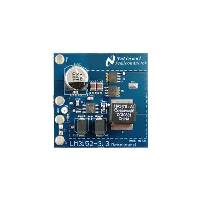
7.0 Board Photos
boardphoto4
FIGURE 3. LM3152-3.3 Demo Board Photo
www.national.com
4
�CONNECTOR POSTS DESCRIPTIONS
Vin: This post is used to connect to the input voltage supply
rail. Input voltage ranges between 6V and 24V and the max
nominal input current is 6A. Appropriate leads should be connected to this terminal that can handle this amount of input
current plus fault conditions which could have input currents
as high 10A peak. Therefore, it is recommended to use 16
gauge wire as a minimum for the input leads.
GND: There are two GND posts which are connected to the
ground of the IC. One should be used for the input voltage
supply and the other should be used for the output voltage.
The GND post closest to the input supply post Vin should be
used for the input supply ground, and likewise the GND post
closest to the output post Vo should be used for the Vo
ground. For the Vin ground connector lead it is recommended
to use 16 gauge wire or larger. Whereas the output ground
connector lead is recommended to use 15 gauge wire or larger.
Vo: This post connects to the output voltage of the
LM3152-3.3 Simple Controller. When connecting the load to
this post, it is recommended to use 15 gauge wire or larger.
The max average load current is designed for 10A with a cur-
MEASURING RIPPLE
To get an accurate measurement of the output ripple voltage
it is necessary to eliminate the long pig-tale from the scope
probe and use a short ground connector or just the shaft of
the barrel to connect to ground. This will minimize parasitic
inductance from the scope probe and allow for a more accurate measurement. The output voltage ripple measurement
should be taken directly across the output capacitors. As a
matter of convenience, the measurement can also be taken
across the output terminals if a ceramic 1µF capacitor is
mounted on Cf (1206 footprint) to minimize parasitic inductance from the terminals to the output capacitors.
COMPONENT TEMPERATURE RISE
The temperature rise of each device was measured on the
case of each device in still air at room temperature.
9.0 Layouts
layout7
FIGURE 4. Top Layer
layout8
FIGURE 5. Bottom Layer
5
www.national.com
RD-164
rent limit of 15A using the Rdson of the low side FET to set
the current limit trip point.
EN: This post is connected to the enable pin of the
LM3152-3.3 IC. When left floating a 1MΩ pull-up resistor to
Vin will enable the device.
8.0 Quick Start
�RD-164
layout9
FIGURE 6. Bottom Silkscreen
10.0 Waveforms
waveform1
FIGURE 7. Component Temp Rise vs Load Vin = 6V
waveform2
FIGURE 8. Component Temp Rise vs Load Vin = 12V
www.national.com
6
�RD-164
waveform3
FIGURE 9. Component Temp Rise vs Load Vin = 18V
waveform4
FIGURE 10. Component Temp Rise vs Load Vin = 24V
waveform7
FIGURE 11. Load Transient 0A to 8A
7
www.national.com
�RD-164
waveform8
FIGURE 12. Load Transient 3.6A to 8A
waveform9
FIGURE 13. Efficiency vs. Load Current
www.national.com
8
�RD-164
Notes
9
www.national.com
�LM3152-3.3 Demonstration Board
Notes
National Semiconductor's design tools attempt to recreate the performance of a substantially equivalent physical implementation of the
design. Reference designs are created using National's published specifications as well as the published specifications of other device
manufacturers. While National does update this information periodically, this information may not be current at the time the reference
design is built. National and/or its licensors do not warrant the accuracy or completeness of the specifications or any information contained
therein. National and/or its licensors do not warrant that any designs or recommended parts will meet the specifications you entered, will
be suitable for your application or fit for any particular purpose, or will operate as shown in the simulation in a physical implementation.
National and/or its licensors do not warrant that the designs are production worthy. You should completely validate and test your design
implementation to confirm the system functionality for your application.
National does not assume any responsibility for use of any circuitry described, no circuit patent licenses are implied and National reserves
the right at any time without notice to change said circuitry and specifications.
For the most current product information visit us at www.national.com.
LIFE SUPPORT POLICY
NATIONAL'S PRODUCTS ARE NOT AUTHORIZED FOR USE AS CRITICAL COMPONENTS IN LIFE SUPPORT DEVICES OR SYSTEMS WITHOUT THE EXPRESS WRITTEN APPROVAL OF THE PRESIDENT AND GENERAL COUNSEL OF NATIONAL SEMICONDUCTOR CORPORATION. As used herein:
1.
Life support devices or systems are devices or systems which, 2.
(a) are intended for surgical implant into the body, or (b) support
or sustain life, and whose failure to perform when properly used
in accordance with instructions for use provided in the labeling,
can be reasonably expected to result in a significant injury to
the user.
A critical component is any component of a life support device
or system whose failure to perform can be reasonably expected
to cause the failure of the life support device or system, or to
affect its safety or effectiveness.
BANNED SUBSTANCE COMPLIANCE
National Semiconductor certifies that the products and packing materials meet the provisions of the Customer Products Stewardship
Specification (CSP-9-111C2) and the Banned Substances and Materials of Interest Specification (CSP-9-111S2) and contain no "Banned
Substances" as defined in CSP-9-111S2.
Leadfree products are RoHS compliant.
RD-164
National Semiconductor
Americas Customer
Support Center
Email:
new.feedback@nsc.com
Tel: 1-800-272-9959
www.national.com
National Semiconductor Europe
Customer Support Center
Fax: +49 (0) 180-530-85-86
Email: europe.support@nsc.com
Deutsch Tel: +49 (0) 69 9508 6208
English Tel: +49 (0) 870 24 0 2171
Français Tel: +33 (0) 1 41 91 8790
National Semiconductor Asia
Pacific Customer Support Center
Email: ap.support@nsc.com
National Semiconductor Japan
Customer Support Center
Fax: 81-3-5639-7507
Email: jpn.feedback@nsc.com
Tel: 81-3-5639-7560
�IMPORTANT NOTICE
Texas Instruments Incorporated and its subsidiaries (TI) reserve the right to make corrections, modifications, enhancements, improvements,
and other changes to its products and services at any time and to discontinue any product or service without notice. Customers should
obtain the latest relevant information before placing orders and should verify that such information is current and complete. All products are
sold subject to TI’s terms and conditions of sale supplied at the time of order acknowledgment.
TI warrants performance of its hardware products to the specifications applicable at the time of sale in accordance with TI’s standard
warranty. Testing and other quality control techniques are used to the extent TI deems necessary to support this warranty. Except where
mandated by government requirements, testing of all parameters of each product is not necessarily performed.
TI assumes no liability for applications assistance or customer product design. Customers are responsible for their products and
applications using TI components. To minimize the risks associated with customer products and applications, customers should provide
adequate design and operating safeguards.
TI does not warrant or represent that any license, either express or implied, is granted under any TI patent right, copyright, mask work right,
or other TI intellectual property right relating to any combination, machine, or process in which TI products or services are used. Information
published by TI regarding third-party products or services does not constitute a license from TI to use such products or services or a
warranty or endorsement thereof. Use of such information may require a license from a third party under the patents or other intellectual
property of the third party, or a license from TI under the patents or other intellectual property of TI.
Reproduction of TI information in TI data books or data sheets is permissible only if reproduction is without alteration and is accompanied
by all associated warranties, conditions, limitations, and notices. Reproduction of this information with alteration is an unfair and deceptive
business practice. TI is not responsible or liable for such altered documentation. Information of third parties may be subject to additional
restrictions.
Resale of TI products or services with statements different from or beyond the parameters stated by TI for that product or service voids all
express and any implied warranties for the associated TI product or service and is an unfair and deceptive business practice. TI is not
responsible or liable for any such statements.
TI products are not authorized for use in safety-critical applications (such as life support) where a failure of the TI product would reasonably
be expected to cause severe personal injury or death, unless officers of the parties have executed an agreement specifically governing
such use. Buyers represent that they have all necessary expertise in the safety and regulatory ramifications of their applications, and
acknowledge and agree that they are solely responsible for all legal, regulatory and safety-related requirements concerning their products
and any use of TI products in such safety-critical applications, notwithstanding any applications-related information or support that may be
provided by TI. Further, Buyers must fully indemnify TI and its representatives against any damages arising out of the use of TI products in
such safety-critical applications.
TI products are neither designed nor intended for use in military/aerospace applications or environments unless the TI products are
specifically designated by TI as military-grade or "enhanced plastic." Only products designated by TI as military-grade meet military
specifications. Buyers acknowledge and agree that any such use of TI products which TI has not designated as military-grade is solely at
the Buyer's risk, and that they are solely responsible for compliance with all legal and regulatory requirements in connection with such use.
TI products are neither designed nor intended for use in automotive applications or environments unless the specific TI products are
designated by TI as compliant with ISO/TS 16949 requirements. Buyers acknowledge and agree that, if they use any non-designated
products in automotive applications, TI will not be responsible for any failure to meet such requirements.
Following are URLs where you can obtain information on other Texas Instruments products and application solutions:
Products
Applications
Audio
www.ti.com/audio
Automotive and Transportation www.ti.com/automotive
Amplifiers
amplifier.ti.com
Communications and Telecom www.ti.com/communications
Data Converters
dataconverter.ti.com
Computers and Peripherals
www.ti.com/computers
DLP® Products
www.dlp.com
Consumer Electronics
www.ti.com/consumer-apps
DSP
dsp.ti.com
Energy and Lighting
www.ti.com/energy
Clocks and Timers
www.ti.com/clocks
Industrial
www.ti.com/industrial
Interface
interface.ti.com
Medical
www.ti.com/medical
Logic
logic.ti.com
Security
www.ti.com/security
Power Mgmt
power.ti.com
Space, Avionics and Defense
www.ti.com/space-avionics-defense
Microcontrollers
microcontroller.ti.com
Video and Imaging
www.ti.com/video
RFID
www.ti-rfid.com
OMAP Mobile Processors
www.ti.com/omap
Wireless Connectivity
www.ti.com/wirelessconnectivity
TI E2E Community Home Page
e2e.ti.com
Mailing Address: Texas Instruments, Post Office Box 655303, Dallas, Texas 75265
Copyright © 2012, Texas Instruments Incorporated
�