Product
Folder
Sample &
Buy
Support &
Community
Tools &
Software
Technical
Documents
LM3560
SNOSB43C – SEPTEMBER 2011 – REVISED NOVEMBER 2016
LM3560 Synchronous Boost Flash Driver
With Dual 1-A High-Side Current Sources (2-A Total Flash Current)
1 Features
3 Description
•
The LM3560 is a 2-MHz fixed frequency synchronous
boost converter with two 1000-mA constant current
drivers for high-current white LEDs. The dual highside current sources allow for grounded cathode LED
operation and can be tied together for providing flash
currents at up to 2 A through a single LED. An
adaptive regulation method ensures the current for
each LED remains in regulation and maximizes
efficiency.
1
•
•
•
•
•
•
•
•
•
•
•
•
•
•
Dual High-Side Current Sources Allow for
Grounded Cathode LED Operation
Accurate and Programmable LED Current from
31.25 mA to 2 A
Independent LED Current Source Programmability
Up to 90% Efficient
Ultra-Small Solution Size: < 26 mm2
Four Operating Modes: Torch, Flash, Privacy
Indicate, and Message Indicator
4-Bit ADC for VLED Monitoring
LED Thermal Sensing and Current Scale-Back
Hardware Flash and Torch Enable
Dual Synchronization Inputs for RF Power
Amplifier Pulse Events
LED and Output Disconnect During Shutdown
Open and Short LED Detection
400-kHz I2C-Compatible Interface
Active Low Hardware Reset
−40°C to +85°C Ambient Temperature Range
The LM3560 is controlled via an I2C-compatible
interface. Features include an internal 4-bit ADC to
monitor the LED voltage, independent LED current
control, a hardware flash enable allowing a logic input
to trigger the flash pulse, dual TX inputs which force
the flash pulse into a low-current torch mode allowing
for synchronization to RF power amplifier events or
other high-current conditions, and an integrated
comparator designed to monitor an NTC thermistor
and provide an interrupt to the LED current.
Additionally, an active high HWEN input provides a
hardware shutdown during system software failures.
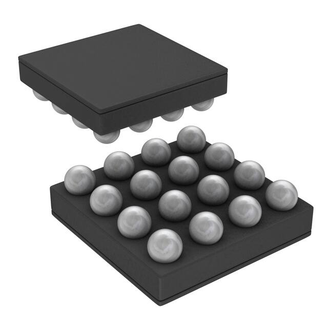
The device is available in an ultra-small 16-pin
DSBGA package. The 2-MHz switching frequency,
overvoltage protection and adjustable current limit
allow for the use of tiny, low-profile (1-µH and 2.2-µH)
inductors and ceramic (10-µF) capacitors.
2 Applications
•
•
Camera Phone LED Flash
White LED Biasing
Device Information(1)
PART NUMBER
LM3560
PACKAGE
DSBGA (16)
BODY SIZE (NOM)
1.96 mm × 1.96 mm
(1) For all available packages, see the orderable addendum at
the end of the data sheet.
Typical Application
1 PH/2.2 PH
SW
IN
2.5 V to 5.5 V
10 PF
OUT
10 PF
LM3560
LED1
HWEN
STROBE
LED2
Flash
LED2
TX1/TORCH
TX2
SDA
LEDI/NTC
SCL
GND
Flash
LED1
Optional Indicator Current
Source or Thermistor
Sensing Circuit
Copyright © 2016, Texas Instruments Incorporated
1
An IMPORTANT NOTICE at the end of this data sheet addresses availability, warranty, changes, use in safety-critical applications,
intellectual property matters and other important disclaimers. PRODUCTION DATA.
�LM3560
SNOSB43C – SEPTEMBER 2011 – REVISED NOVEMBER 2016
www.ti.com
Table of Contents
1
2
3
4
5
6
7
Features ..................................................................
Applications ...........................................................
Description .............................................................
Revision History.....................................................
Pin Configuration and Functions .........................
Specifications.........................................................
1
1
1
2
3
4
6.1
6.2
6.3
6.4
6.5
6.6
6.7
4
4
4
4
5
7
8
Absolute Maximum Ratings ......................................
ESD Ratings..............................................................
Recommended Operating Conditions.......................
Thermal Information ..................................................
Electrical Characteristics...........................................
I2C Timing Specifications (SCL, SDA) ......................
Typical Characteristics ..............................................
Detailed Description ............................................ 12
7.1
7.2
7.3
7.4
Overview .................................................................
Functional Block Diagram .......................................
Feature Description.................................................
Device Functional Modes........................................
12
13
14
22
7.5 I2C-Compatible Interface......................................... 28
7.6 Register Descriptions .............................................. 30
8
Application and Implementation ........................ 39
8.1 Application Information............................................ 39
8.2 Typical Application ................................................. 39
9 Power Supply Recommendations...................... 43
10 Layout................................................................... 44
10.1 Layout Recommendations .................................... 44
10.2 Layout Example .................................................... 45
11 Device and Documentation Support ................. 46
11.1
11.2
11.3
11.4
11.5
11.6
11.7
Device Support......................................................
Documentation Support ........................................
Receiving Notification of Documentation Updates
Community Resources..........................................
Trademarks ...........................................................
Electrostatic Discharge Caution ............................
Glossary ................................................................
46
46
46
46
46
46
46
12 Mechanical, Packaging, and Orderable
Information ........................................................... 46
4 Revision History
NOTE: Page numbers for previous revisions may differ from page numbers in the current version.
Changes from Revision B (August 2013) to Revision C
Page
•
Added Device Information and Pin Configuration and Functions sections, ESD Ratings and Thermal Information
tables, Feature Description, Device Functional Modes, Application and Implementation, Power Supply
Recommendations, Layout, Device and Documentation Support, and Mechanical, Packaging, and Orderable
Information sections................................................................................................................................................................ 1
•
Deleted Maximum Lead Temperature row per new TI data sheet standards ....................................................................... 4
•
Changed RθJA from "50.4°C/W" to "71.4°C/W"; add additional thermal values ...................................................................... 4
2
Submit Documentation Feedback
Copyright © 2011–2016, Texas Instruments Incorporated
Product Folder Links: LM3560
�LM3560
www.ti.com
SNOSB43C – SEPTEMBER 2011 – REVISED NOVEMBER 2016
5 Pin Configuration and Functions
YZR Package
16-Pin DSBGA
Top View
A1
A2
A3
A4
B1
B2
B3
B4
C1
C2
C3
C4
D1
D2
D3
D4
Pin Functions
PIN
TYPE
DESCRIPTION
NO.
NAME
A1
LED1
Power
High-side current source output for flash LED
OUT
Power
Step-up DC-DC converter output. Connect a 10-µF ceramic capacitor between this pin and
GND.
A2, B2
A3, B3
SW
Power
Drain connection for internal NMOS and synchronous PMOS switches.
A4, B4
GND
Ground
Ground
B1
LED2
Output
High-side current source output for flash LED
C1
LEDI/NTC
Power
Configurable as a high-side current source output for indicator LED or comparator input for
LED temperature sensing.
C2
TX1/TORCH/
GPIO1
Input/Output
STROBE
Input
Active high hardware flash enable. Drive STROBE high to turn on the flash pulse. This pin
has an internal 300-kΩ pulldown to GND.
IN
Power
Input voltage connection. Connect IN to the input supply, and bypass to GND with a minimum
10-µF ceramic capacitor.
TX2/INT/GPIO2
Input/Output
Configurable as a dual-polarity power amplifier synchronization Input, an Interrupt Output, or
as a general purpose logic I/O. This pin has an internal 300-kΩ pulldown to GND.
D2
SDA
Input/Output
Serial data input/output. High impedance in shutdown or in power down.
D3
SCL
Input
Serial clock input. High impedance in shutdown or in power down.
D4
HWEN
Input
Logic high hardware enable. HWEN is a high-impedance input and is normally connected
with an external pullup resistor to a logic high voltage.
C3
C4
D1
Configurable as a dual-polarity rf power amplifier synchronization input, an interrupt output, or
as a general purpose logic I/O. This pin has an internal 300-kΩ pulldown to GND.
Submit Documentation Feedback
Copyright © 2011–2016, Texas Instruments Incorporated
Product Folder Links: LM3560
3
�LM3560
SNOSB43C – SEPTEMBER 2011 – REVISED NOVEMBER 2016
www.ti.com
6 Specifications
6.1 Absolute Maximum Ratings
over operating free-air temperature range (unless otherwise noted) (1)
MIN
MAX
UNIT
VIN, VSW, VOUT
–0.3
6
V
VSCL, VSDA, VHWEN, VSTROBE, VTX1, VTX2, VLED1, VLED2, VLEDI/NTC
–0.3
to the lesser of (VIN + 0.3
V) with 6 V maximum
V
Continuous power dissipation (2)
Internally limited
Junction temperature, TJ-MAX
Storage temperature, Tstg
(1)
(2)
–65
150
°C
150
°C
Stresses beyond those listed under Absolute Maximum Ratings may cause permanent damage to the device. These are stress ratings
only, which do not imply functional operation of the device at these or any other conditions beyond those indicated under Recommended
Operating Conditions. Exposure to absolute-maximum-rated conditions for extended periods may affect device reliability.
Internal thermal shutdown circuitry protects the device from permanent damage. Thermal shutdown engages at TJ = 150°C (typical) and
disengages at TJ = 135°C (typical). Thermal shutdown is ensured by design.
6.2 ESD Ratings
V(ESD)
(1)
Electrostatic discharge
VALUE
UNIT
±2000
V
Human-body model (HBM), per ANSI/ESDA/JEDEC JS-001 (1)
JEDEC document JEP155 states that 500-V HBM allows safe manufacturing with a standard ESD control process.
6.3 Recommended Operating Conditions
over operating free-air temperature range (unless otherwise noted)
MIN
MAX
UNIT
Input voltage, VIN
2.5
5.5
V
Junction temperature, TJ
–40
125
°C
Ambient temperature, TA (1)
–40
85
°C
(1)
In applications where high power dissipation and/or poor package thermal resistance is present, the maximum ambient temperature may
have to be derated. Maximum ambient temperature (TA-MAX) is dependent on the maximum operating junction temperature (TJ-MAX-OP =
125°C), the maximum power dissipation of the device in the application (PD-MAX), and the junction-to-ambient thermal resistance of the
device package in the application (RθJA), as given by the following equation: TA-MAX = TJ-MAX-OP – (RθJA × PD-MAX).
6.4 Thermal Information
LM3560
THERMAL METRIC (1)
YZR (DSBGA)
UNIT
16 PINS
RθJA
Junction-to-ambient thermal resistance
71.4
°C/W
RθJC(top)
Junction-to-case (top) thermal resistance
0.4
°C/W
RθJB
Junction-to-board thermal resistance
12.4
°C/W
ψJT
Junction-to-top characterization parameter
0.3
°C/W
ψJB
Junction-to-board characterization parameter
12.6
°C/W
(1)
4
For more information about traditional and new thermal metrics, see Semiconductor and IC Package Thermal Metrics.
Submit Documentation Feedback
Copyright © 2011–2016, Texas Instruments Incorporated
Product Folder Links: LM3560
�LM3560
www.ti.com
SNOSB43C – SEPTEMBER 2011 – REVISED NOVEMBER 2016
6.5 Electrical Characteristics
Unless otherwise specified, VIN = 3.6 V, VHWEN = VIN, TA = 25°C. (1)
PARAMETER
(2)
TEST CONDITIONS
MIN
TYP
MAX
1000-mA flash current setting, per
current source
–3.5%
2000
3.5%
1000-mA flash current setting, per
current source
–40°C ≤ TA ≤ 85°C
–5%
UNIT
CURRENT SOURCE SPECIFICATIONS
Current source
accuracy
ILED
ILED1 + ILED2
3 V ≤ VIN ≤ 4.2 V
VOUT = 4.5 V
VOUT – VLED1/2
Current source
regulation voltage
VOVP
Output overvoltage
protection trip point (3)
mA
31.25-mA torch current, per
current source
31.25-mA torch current, per
current source
–40°C ≤ TA ≤ 85°C
5%
62.5
–10%
ILED = 2 A (ILED1 + ILED2), VOUT = 4.5 V
10%
300
ON threshold
mV
5
ON threshold, –40°C ≤ TA ≤ 85°C
4.925
OFF threshold
5.075
V
4.8
STEP-UP DC-DC CONVERTER SPECIFICATIONS
RPMOS
PMOS switch onresistance
IPMOS = 1 A
80
mΩ
RNMOS
NMOS switch onresistance
INMOS = 1 A
65
mΩ
CL bits = 00
1.6
CL bits = 00, 3 V ≤ VIN ≤ 4.2 V
–40°C ≤ TA ≤ 85°C
1.44
CL bits = 01
Switch current limit (4)
ICL
2.3
CL bits = 01, 3 V ≤ VIN ≤ 4.2 V
–40°C ≤ TA ≤ 85°C
2.02
CL bits = 10
2.64
CL bits = 11
VTRIP
(1)
(2)
(3)
(4)
Indicator current
Comparator trip
threshold
3.36
3.17
VOUT < 2.3 V
4.03
300
Message indicator register, bits[2:0] = 111
VLEDI/NTC = 2 V
ILEDI/NTC
A
3.6
CL bits = 11, 3 V ≤ VIN ≤ 4.2 V
–40°C ≤ TA ≤ 85°C
Output short-circuit
current limit
2.58
3
CL bits = 10, 3 V ≤ VIN ≤ 4.2 V
–40°C ≤ TA ≤ 85°C
IOUT_SC
1.76
Message indicator register, bits[2:0] = 111, 3 V ≤ VIN
≤ 4.2 V
VLEDI/NTC = 2 V, –40°C ≤ TA ≤ 85°C
18
mA
16
Configuration register 1, bit [4] = 1,
Configuration register 1, bit [4] = 1,
3 V ≤ VIN ≤ 4.2 V, –40°C ≤ TA ≤ 85°C
mA
20
1
0.97
1.03
V
All voltages are with respect to the potential at the GND pin.
Minimum (MIN) and maximum (MAX) limits are specified by design, test, or statistical analysis. Typical (TYP) numbers represent the
most likely norm. Unless otherwise stated, conditions for typical specifications are: VIN = 3.6 V and TA = 25°C.
The typical curve for overvoltage protection (OVP) is measured in closed loop using Figure 41 . The OVP value is found by forcing an
open circuit in the LED1 and LED2 path and recording the peak value of VOUT. The value given in Electrical Characteristics is found in
an open loop configuration by ramping the voltage at OUT until the OVP comparator trips. The closed loop data can appear higher due
to the stored energy in the inductor being dumped into the output capacitor after the OVP comparator trips. Worst case is an open circuit
condition where the output voltage can continue to rise after the OVP comparator trips by approximately IIN × sqrt(L/COUT).
The typical curve for current limit is measured in closed loop using Figure 41, and increasing IOUT until the peak inductor current stops
increasing. The value given in Electrical Characteristics is measured open loop and is found by forcing current into SW until the current
limit comparator threshold is reached. Closed loop data appears higher due to the delay between the comparator trip point and the
NFET turning off. This delay allows the closed loop inductor current to ramp higher after the trip point by approximately 20 ns × VIN/L.
Submit Documentation Feedback
Copyright © 2011–2016, Texas Instruments Incorporated
Product Folder Links: LM3560
5
�LM3560
SNOSB43C – SEPTEMBER 2011 – REVISED NOVEMBER 2016
www.ti.com
Electrical Characteristics (continued)
Unless otherwise specified, VIN = 3.6 V, VHWEN = VIN, TA = 25°C.(1) (2)
PARAMETER
ƒSW
Switching frequency
tTIMEOUT
Timeout duration (5) (6)
IQ
Quiescent supply
current
TEST CONDITIONS
MIN
3 V ≤ VIN ≤ 4.2 V, –40°C ≤ TA ≤ 85°C
1.8
MAX
2.2
–10%
10%
2
3 V ≤ VIN ≤ 4.2 V
UNIT
MHz
ms
Device not switching, VOUT = 3 V
900
µA
Device switching, VOUT = 4.5 V
1.97
mA
Indicate mode, message indicator register bits [2:0] =
111
590
µA
3 V ≤ VIN ≤ 4.2 V
0.02
ISHDN
Shutdown supply
current
ISTBY
Standby supply
current
VIN_TH
VIN monitor threshold
VIN_FLASH_TH
VIN flash monitor
threshold
VIN monitor register = 0x08
Flash-to-torch LED
current settling time
TX_ Low to high
ILED1 + ILED2 = 2 A to 187.5 mA
Torch-to-flash LED
current Settling
TX_High to low
ILED1 + ILED2 = 187.5 mA to 2 mA
Time from when ILED
hits target until VLED
data is available
ADC delay register bit [5] = 1
tD
VF_ADC
ADC threshold
tTX
TYP
3 V ≤ VIN ≤ 4.2 V, –40°C ≤ TA ≤ 85°C
1.25
1.25
3 V ≤ VIN ≤ 4.2 V, –40°C ≤ TA ≤ 85°C
2
VIN monitor register = 0x01
VIN monitor register = 0x01, –40°C ≤ TA ≤ 85°C
VIN monitor register = 0x08, –40°C ≤ TA ≤ 85°C
2.9
2.85
2.95
2.9
2.85
2.95
µA
V
V
2
µs
160
16
ADC delay register bit [5] = 0
ADC delay register bits [4:0] = 0000
250
VLED monitor register bits [3:0] = 1111
4.2
VLED monitor register bits [3:0] = 1111
3 V ≤ VIN ≤ 4.2 V, –40°C ≤ TA ≤ 85°C
µA
4.05
µs
4.35
V
HWEN, STROBE, TX1/TORCH/GPIO1, TX2/INT/GPIO2 VOLTAGE SPECIFICATIONS
VIL
Input logic low
2.7 V ≤ VIN ≤ 4.2 V, –40°C ≤ TA ≤ 85°C
0
0.4
V
VIH
Input logic high
2.7 V ≤ VIN ≤ 4.2 V, –40°C ≤ TA ≤ 85°C
1.2
VIN
V
RPD
Internal pulldown
resistance on TX1,
TX2, STROBE
300
kΩ
I2C-COMPATIBLE VOLTAGE SPECIFICATIONS (SCL, SDA)
VIL
Input logic low
2.7 V ≤ VIN ≤ 4.2 V, –40°C ≤ TA ≤ 85°C
0
0.4
V
VIH
Input logic high
2.7 V ≤ VIN ≤ 4.2 V, –40°C ≤ TA ≤ 85°C
1.3
VIN
V
VOL
Output logic low
(SDA)
ILOAD = 3 mA
2.7 V ≤ VIN ≤ 4.2 V, –40°C ≤ TA ≤ 85°C
0.4
V
(5)
(6)
6
Specified by design. Not production tested.
The timeout period is a divided down representation of the 2-MHz clock; thus, the accuracy specification is the same as the switching
frequency.
Submit Documentation Feedback
Copyright © 2011–2016, Texas Instruments Incorporated
Product Folder Links: LM3560
�LM3560
www.ti.com
SNOSB43C – SEPTEMBER 2011 – REVISED NOVEMBER 2016
6.6 I2C Timing Specifications (SCL, SDA)
All minimum and maximum values apply over –40°C ≤ TA ≤ 85°C and are specified by design (not production tested); see (1)
MIN
MAX
UNIT
ƒSCL
SCL (clock frequency)
0
400
kHz
tRISE
Rise time of both SDA and SCL
20 ns + 0.1 × CBUS
300
ns
tFALL
Fall time of both SDA and SCL
20 ns + 0.1 × CBUS
300
tLOW
Low period of SCL clock
1.3
µs
tHIGH
High period of SCL clock
600
ns
tHD;STA
Hold time for start (or repeated start) condition
600
ns
tSU:STA
Set-up time for a repeated start
600
ns
tHD:DAT
Data hold time
0
ns
tSU:DAT
Data set-up time
100
ns
tSU:STO
Set-up time for stop condition
600
ns
tVD:DAT
Data valid time
900
tVD;ACK
Data valid acknowledge time
900
tBUF
Bus-free time between a start and stop condition
(1)
1.3
ns
ns
ns
µs
Specified by design, not production tested.
Submit Documentation Feedback
Copyright © 2011–2016, Texas Instruments Incorporated
Product Folder Links: LM3560
7
�LM3560
SNOSB43C – SEPTEMBER 2011 – REVISED NOVEMBER 2016
www.ti.com
6.7 Typical Characteristics
VIN = 3.6 V, COUT = 10 µF, CIN = 10 µF, L = 1 µH (TOKO FDSD0312-1R0, RL = 43 mΩ), TA = 25°C, ILED = ILED1 + ILED2, unless
otherwise noted.
1.60
2.03
Code 1111
1.55
1.99
Code 1110
1.45
1.91
Code 1010
1.40
1.87
1.83
Code 1101
1.79
1.75
1.71
1.35
ILED (A)
ILED (A)
Code 1011
1.50
1.95
1.30
1.20
Code 1100
1.67
1.15
1.63
1.10
1.59
1.05
1.55
2.5
2.9
3.3
3.7
4.1
Code 1001
1.25
Code 1000
1.00
2.5
4.5
2.9
3.3
Highest 4 Flash Brightness Codes
0.490
0.450
0.95
Code 0011
0.410
Code 0110
0.370
ILED (A)
0.90
ILED (A)
4.9
0.530
Code 0111
1.00
0.85
0.80
Code 0101
0.75
0.330
Code 0010
0.290
0.250
0.210
0.70
Code 0001
0.170
Code 0100
0.65
0.130
0.60
0.090
0.55
2.5
2.9
3.3
3.7
4.1
4.5
Code 0000
0.050
2.5
4.9
VIN (V)
Figure 3. ILED vs VIN, ILED1 + ILED2
3.7
4.1
4.5
4.9
Figure 4. ILED vs VIN, ILED1 + ILED2
10.0
9.0
Code 111
19.0
Code 011
8.0
17.0
Indicate Current (mA)
18.0
Code 110
16.0
15.0
Code 101
14.0
13.0
12.0
7.0
Code 010
6.0
5.0
4.0
Code 001
3.0
2.0
Code 100
Code 000
1.0
11.0
0.24
0.28
0.32
0.36
0.40
0.0
0.00 0.03 0.05 0.08 0.10 0.13 0.15 0.18 0.20
Headroom Voltage (VIN - VLED)
Headroom Voltage (VIN - VLED)
VLED = 2.5 V
3.3
Lowest 4 Flash Brightness Codes
20.0
10.0
0.20
2.9
VIN (V)
Lower Middle 4 Flash Brightness Codes
Indicate Current (mA)
4.5
Figure 2. ILED vs VIN, ILED1 + ILED2
1.10
Indicate Codes 100 - 111
Figure 5. Indicator Current vs Headroom Voltage
8
4.1
Upper Middle 4 Flash Brightness Codes
Figure 1. ILED vs VIN, ILED1 + ILED2
1.05
3.7
VIN (V)
VIN (V)
VLED = 2.5 V
Indicate Codes 000 - 011
Figure 6. Indicator Currents vs Headroom Voltage
Submit Documentation Feedback
Copyright © 2011–2016, Texas Instruments Incorporated
Product Folder Links: LM3560
�LM3560
www.ti.com
SNOSB43C – SEPTEMBER 2011 – REVISED NOVEMBER 2016
Typical Characteristics (continued)
VIN = 3.6 V, COUT = 10 µF, CIN = 10 µF, L = 1 µH (TOKO FDSD0312-1R0, RL = 43 mΩ), TA = 25°C, ILED = ILED1 + ILED2, unless
otherwise noted.
1.7
2.00
1.5
1.96
Stand-by Current (#A)
Switching Frequency (MHz)
25°C
1.98
-40°C
1.94
85°C
2.8
3.2
3.5
1.3
1.0
25°C
-40°C
0.8
1.92
1.90
2.5
85°C
3.9
0.6
2.5
4.2
3.0
3.5
4.1
4.6
5.1
VIN (V)
VIN (V)
HWEN = VIN
Figure 7. Switching Frequency vs VIN
Figure 8. Stand-By Supply Current vs VIN
HWEN = GND
Figure 9. Shutdown Supply Current vs VIN
VIN_FLASH_TH = 3.2 V
Circuit Of Figure 27 (Note 1)
TX2 Set For Interrupt Output (INT)
Figure 10. Strobe-to-Flash LED Current Response
VIN_TH = 3.2 V
Circuit of Figure 27 (Note 2)
Figure 11. VIN Flash Monitor Operation
TX2 Set For Interrupt Output (INT)
Force Torch Mode
Figure 12. VIN Monitor Operation
Submit Documentation Feedback
Copyright © 2011–2016, Texas Instruments Incorporated
Product Folder Links: LM3560
9
�LM3560
SNOSB43C – SEPTEMBER 2011 – REVISED NOVEMBER 2016
www.ti.com
Typical Characteristics (continued)
VIN = 3.6 V, COUT = 10 µF, CIN = 10 µF, L = 1 µH (TOKO FDSD0312-1R0, RL = 43 mΩ), TA = 25°C, ILED = ILED1 + ILED2, unless
otherwise noted.
TX2 Set for Interrupt Output (INT)
Circuit of Figure 42
R3 = 1.3 kΩ
RNTC = 10 kΩ at
25°C
Beta = 3380 k
NTC Set to Force Torch Mode
Figure 14. AET Operation
Figure 13. NTC Operation
Force Torch
Figure 16. TX1 Interrupt
Figure 15. HWEN Operation Device Enabled in Flash Mode
3.90
3.34
3.31
3.85
Current Limit (A)
Current Limit (A)
3.29
3.80
-40°C
3.75
25°C
-40°C
3.23
25°C
3.21
3.18
3.70
3.16
85°C
3.65
2.6
3.26
2.9
3.2
3.6
3.9
85°C
3.13
2.6
4.2
2.9
3.2
VIN (V)
3.6-A Setting
See Note 1
3-A Setting
Figure 17. Closed Loop Current Limit vs VIN
10
3.6
3.9
4.2
VIN (V)
See Note 1
Figure 18. Closed Loop Current Limit vs VIN
Submit Documentation Feedback
Copyright © 2011–2016, Texas Instruments Incorporated
Product Folder Links: LM3560
�LM3560
www.ti.com
SNOSB43C – SEPTEMBER 2011 – REVISED NOVEMBER 2016
Typical Characteristics (continued)
VIN = 3.6 V, COUT = 10 µF, CIN = 10 µF, L = 1 µH (TOKO FDSD0312-1R0, RL = 43 mΩ), TA = 25°C, ILED = ILED1 + ILED2, unless
otherwise noted.
1.91
2.75
1.87
-40°C
2.70
1.84
Current Limit (A)
Current Limit (A)
-40°C
2.65
2.60
25°C
2.55
1.81
1.78
25°C
1.75
85°C
1.71
2.50
1.68
85°C
2.45
2.6
2.9
3.2
3.6
3.9
1.65
2.6
4.2
2.3-A Setting
2.9
3.2
3.6
3.9
4.2
VIN (V)
VIN (V)
See Note 2
1.6-A Setting
Figure 19. Closed Loop Current Limit vs VIN
See Note 2
Figure 20. Closed Loop Current Limit vs VIN
(1)
The typical curve for current limit is measured in closed loop using Figure 41, and increasing IOUT until the peak
inductor current stops increasing. The value given in Electrical Characteristics is measured open loop and is found
by forcing current into SW until the current limit comparator threshold is reached. Closed loop data appears higher
due to the delay between the comparator trip point and the NFET turning off. This delay allows the closed loop
inductor current to ramp higher after the trip point by approximately 20 ns × VIN/L.
(2)
The typical curve for overvoltage protection (OVP) is measured in closed loop using Figure 41 . The OVP value is
found by forcing an open circuit in the LED1 and LED2 path and recording the peak value of VOUT. The value given
in Electrical Characteristics is found in an open loop configuration by ramping the voltage at OUT until the OVP
comparator trips. The closed loop data can appear higher due to the stored energy in the inductor being dumped
into the output capacitor after the OVP comparator trips. Worst case is an open circuit condition where the output
voltage can continue to rise after the OVP comparator trips by approximately IIN × sqrt(L/COUT).
Submit Documentation Feedback
Copyright © 2011–2016, Texas Instruments Incorporated
Product Folder Links: LM3560
11
�LM3560
SNOSB43C – SEPTEMBER 2011 – REVISED NOVEMBER 2016
www.ti.com
7 Detailed Description
7.1 Overview
The LM3560 is a high-power white-LED flash driver capable of delivering up to 2 A of LED current into a single
LED or up to 1 A into two parallel LEDs. The device incorporates a 2-MHz constant frequency, a synchronous
boost converter, and two high-side current sources to regulate the LED current over the 2.5-V to 5.5-V input
voltage range.
During operation when the output voltage is greater than VIN – 150 mV the boost converter switches and
maintains at least 300 mV across both current sources (LED1 and LED2). This minimum headroom voltage
ensures that the current sources remain in regulation. When the input voltage rises above the LED voltage +
current source headroom voltage, the device stops switching and turns the PFET on continuously (pass mode).
In pass mode the difference between (VIN – ILED × RON_P) and the voltage across the LEDs is dropped across the
current sources.
Four hardware control pins provide control of the LM3560. These include a hardware flash enable (STROBE),
dual flash Interrupt inputs (TX1 and TX2) designed to interrupt the flash pulse during high battery current
conditions, and a logic high hardware enable (HWEN) that can be pulled low to rapidly place the device into
shutdown. Additional features of the LM3560 include an internal 4-bit ADC for LED voltage monitoring, an
internal comparator for LED thermal sensing via an external NTC thermistor, an input voltage monitor that can
reduce the flash current during input undervoltage conditions, a low-power message indicator LED current
source, and a mode for utilizing the flash LEDs as a privacy indicator.
Control of the LM3560 is done via an I2C-compatible interface. This includes adjustment of the flash and torch
current levels, adjustment of the indicator LED currents, changing the flash timeout duration, changing the switch
current limit, and reading back the ADC results. Additionally, there are 8 flag bits that indicate flash current timeout, LED overtemperature, LED failure (LED short or output OVP condition), device thermal shutdown, VIN
undervoltage condition, VIN flash monitor undervoltage condition, and the occurrence of a TX1 or TX2 interrupt.
12
Submit Documentation Feedback
Copyright © 2011–2016, Texas Instruments Incorporated
Product Folder Links: LM3560
�LM3560
www.ti.com
SNOSB43C – SEPTEMBER 2011 – REVISED NOVEMBER 2016
7.2 Functional Block Diagram
SW
Over Voltage
Comparator
2 MHz
Oscillator
VREF
+
-
IN
80 mW
VIN Flash
Monitor
Threshold
VIN Monitor
Threshold
V OVP
OUT
ILED1
ILED2
+
-
+
-
PWM
Control
LED1
65 mW
ILEDI
Thermal
Shutdown
o
+150 C
LEDI/NTC
+
-
Error
Amplifier
LED2
V HR
+
-
+
-
Current Sense/
Current Limit
Max
VLED
1V
Slope
Compensation
SDA
2
SCL
I C
Interface
Soft-Start
Control
Logic/
Registers
ADC
4 Bits
HWEN
TX1/TORCH/
GPIO1
STROBE
TX2/INT/
GPIO2
GND
Copyright © 2016, Texas Instruments Incorporated
Submit Documentation Feedback
Copyright © 2011–2016, Texas Instruments Incorporated
Product Folder Links: LM3560
13
�LM3560
SNOSB43C – SEPTEMBER 2011 – REVISED NOVEMBER 2016
www.ti.com
7.3 Feature Description
7.3.1 Power Amplifier Synchronization (Tx1)
The TX1/TORCH/GPIO1 pin has a triple function. With configuration register 1 bit [7] = 0 (default)
TX1/TORCH/GPIO1 is a power amplifier synchronization input (TX1 mode). This mode is designed to reduce the
flash LED current when TX1 is driven high (active high polarity) or driven low (active low polarity). When the
LM3560 is engaged in a flash event and TX1/TORCH is driven high, the active current sources (LED1 and/or
LED2) are forced into torch mode at the programmed torch current setting. If TX1 is then pulled low before the
flash pulse terminates, the LED current returns to the previous flash current level. At the end of the flash timeout,
whether the TX1/TORCH pin is high or low, the LED current turns off.
The polarity of TX1 can be changed from active high to active low by writing a 0 to bit [5] of Configuration
Register 1. With this bit set to 0 the LM3560 is forced into torch mode when TX1/TORCH is pulled low. Figure 21
details the functionality of the TX1 Interrupt.
7.3.1.1 TX1 Shutdown
TX1 also has the capability to force shutdown. Bit [4] of configuration register 2 set to a 1, changes TX1 from a
force torch when active to a force shutdown when active. For example, if TX1/TORCH/GPIO1 is configured for
TX1 mode with active high polarity, and bit[4] of configuration register 2 is set to 1, then when TX1 is driven high,
the active current sources (LED1 and/or LED2) is forced into shutdown. Once the active current sources are
forced into shutdown by activating TX1, the current sources can only be re-enabled into flash mode if TX1 is
pulled low and the flags register is read back. If only the flags register is read back and TX1 is kept high the
device is re-enabled into torch mode and not shutdown. This occurs because the TX1 shutdown feature is an
edge-triggered event. With active high polarity the TX1 shutdown requires a rising edge at TX1 in order to force
the current source into shutdown. Once shut down, it takes a read back of the flags register and another rising
edge at TX1 to force shutdown again. Figure 34 details the different responses of the TX1 shutdown mode.
Flash Timeout
IFLASH
ITORCH
STROBE
TX1 or TX2 set
for Active High
Figure 21. TX1 or TX2 Interrupt (Force Torch) Response
7.3.2 Independent LED Control
Bits [4:3] of the eenable register provide for independent turnon and turnoff of the LED1 or LED2 current
sources. Once enabled, the LED current is adjusted by writing to the torch brightness or flash brightness
registers depending on whether flash or torch mode is selected. Both the torch brightness and the flash
brightness registers provide for independent current programming for the LED currents in either LED1 or LED2.
(See Torch Brightness Register Descriptions (Address 0xA0) and Flash Brightness Register (Address 0xB0).)
14
Submit Documentation Feedback
Copyright © 2011–2016, Texas Instruments Incorporated
Product Folder Links: LM3560
�LM3560
www.ti.com
SNOSB43C – SEPTEMBER 2011 – REVISED NOVEMBER 2016
Feature Description (continued)
7.3.3 Hardware Torch
With configuration register 1 Bit [7] = 1, TX1/TORCH/GPIO1 is configured as a hardware torch mode enable. In
this mode, a high at TX1/TORCH turns on the LED current at the programmed torch current setting. The
STROBE input and I2C-enabled flash takes precedence over torch mode. In hardware torch mode, both LED1
and LED2 current sources turn off after a flash event and configuration register 1 Bit [7] is reset to 0. In this
situation, to re-enter torch mode via hardware torch, the hardware torch enable bit (configuration register 1 Bit
[7]) must be reset to 1. Figure 22 details the functionality of hardware torch mode.
Flash Duration
IFLASH
ITORCH
STROBE
TORCH
Figure 22. Hardware Torch Mode
7.3.4 Fault Protections
7.3.4.1 Overvoltage Protection
The output voltage is limited to typically 5 V (5.075 V maximum). In situations such as the current source open,
the LM3560 raises the output voltage to try to keep the LED current at its target value. When VOUT reaches 5 V,
the overvoltage comparator trips and turns off both the internal NFET and PFET. When VOUT falls below 4.8 V
(typical), the LM3560 begins switching again.
7.3.4.2 Current Limit
The LM3560 features 4 selectable current limits: 1.6 A, 2.3 A, 3 A, and 3.6 A. These are programmable through
the I2C-compatible interface via bits [6:5] of the flash duration register. When the current limit is reached, the
LM3560 stops switching for the remainder of the switching cycle.
Because the current limit is sensed in the NMOS switch there is no mechanism to limit the current when the
device operates in pass mode. In situations where there could potentially be large load currents at OUT, and the
LM3560 device is operating in pass mode, the load current must be limited to 3 A. In boost mode or pass mode if
VOUT falls below approximately 2.3 V, the device stops switching and the PFET operates as a current source,
limiting the current to typically 350 mA. This prevents damage to the LM3560 and excessive current draw from
the battery during output short-circuit conditions.
7.3.4.3 Flash Timeout
The flash-timeout period sets the amount of time that the flash current is being sourced from current sources
LED1 and LED2. Bits [4:0] of the flash duration register set the flash-timeout period. There are 32 different flashtimeout durations in steps of 32 ms giving a flash timeout range of 32 ms to 1024 ms (see Table 15).
7.3.4.4 Indicator LED/Thermistor (LED1/NTC)
The LEDI/NTC pin serves a dual function: either as a programmable LED message indicator driver or as a
comparator input for negative temperature coefficient (NTC) thermistors.
Submit Documentation Feedback
Copyright © 2011–2016, Texas Instruments Incorporated
Product Folder Links: LM3560
15
�LM3560
SNOSB43C – SEPTEMBER 2011 – REVISED NOVEMBER 2016
www.ti.com
Feature Description (continued)
7.3.4.4.1 Message Indicator Current Source (LEDI/NTC)
LEDI/NTC is configured as a message indicator current source by setting configuration register 1 bit [4] = (0)
default. The indicator current source is enabled/disabled via the enable register bit [6] = (1). Bit [7] of the enable
register enables the message Indicator in blink mode. If the message indicator is set for blinking mode, the
pattern programmed into the indicator register, and indicator blinking register is output on the Indicator current
source.
The indicator blinking register controls the following (see Table 6):
1. Number of blank periods (BLANK #). This has 16 settings. tBLANK = tACTIVE × BLANK# , where tACTIVE =
tPERIOD × PERIOD#
2. Pulse width (tPULSE) has 16 settings between 0 and 480 ms in steps of 32 ms. The pulse width is the duration
that the indicator current is at its programmed set point at the end of the ramp-up time.
The indicator register controls the following (see Table 5):
1. Indicator current level (IIND). There are 8 indicator current levels from 2.25 mA to 18 mA in steps of 2.25 mA.
2. Number of periods (PERIOD #). This has 8 steps. A period (tPERIOD) is found by
tPERIOD = tR + tF + 2 x tPULSE. (see Figure 23 for indicator timing).
3. Ramp times (tR or tF) for turnon and turnoff of the indicator current source. Four programmable times of 78
ms, 156 ms, 312 ms, and 624 ms are available. The ramp times apply for both ramp-up and ramp-down and
are not independently changeable.
tPERIOD
tBLANK
tPERIOD
tPULSE
tPULSE
IIND
tR
tF
tR
tPULSE
tF
tPULSE
Figure 23. Message Indicator Timing Diagram
7.3.4.4.1.1 Message Indicator Example 1 (Single Pulse With Dead Time):
As an example, to set up the message indicator for a 312-ms ramp-up and ramp-down, 192-ms pulse width, and
1 pulse followed by a 5-s delay. The indicator settings is as follows. tR = tF = 312 ms, tWIDTH = 192 ms (tPERIOD =
312 ms × 2 + 192 ms × 2 = 1016 ms). BLANK# setting is: 5s/1016 ms × 1 (PERIOD# = 1). Giving a BLANK#
setting of 5. The resulting waveform appears as:
tPERIOD
(1.016s)
tBLANK
(5.08s)
Figure 24. Message Indicator Example 1
7.3.4.4.1.2 Message Indicator Example 2 (Multiple Pulses With Dead Time):
Another example has the same tR, tF, tPULSE, and tBLANK times as before, but this time the PERIOD# is set to 3.
Now the tACTIVE time is tPERIOD × 3 = 1016 ms × 3 = 3048 ms. This results in a blank time of tBLANK = tACTIVE ×
BLANK# = 3.048 s × 5 = 15.24 s
16
Submit Documentation Feedback
Copyright © 2011–2016, Texas Instruments Incorporated
Product Folder Links: LM3560
�LM3560
www.ti.com
SNOSB43C – SEPTEMBER 2011 – REVISED NOVEMBER 2016
Feature Description (continued)
tACTIVE
(3.048s)
tPERIOD
(1.016s)
tPERIOD
(1.016s)
tPERIOD
(1.016s)
tBLANK
(15.24s)
Figure 25. Message Indicator Example 2
7.3.4.4.2 Updating The Message Indicator
The best way to update the message indicator is to disable the message indicator output via the enable register
bit [6], then write the new sequence to the indicator register and/or indicator blinking register, and then re-enable
the message indicator. Updating the indicator registers while it is active can lead to long delays between pattern
changes. This is especially true if the PERIOD#, or BLANK# setting is changed from a high setting to a lower
setting.
7.3.5 Input Voltage Monitor
The LM3560 has an internal comparator at IN which monitors the input voltage and can force the LED current
into torch mode or into shutdown if VIN falls below the programmable VIN monitor threshold. Bit 0 in the VIN
monitor register enables or disables this feature. When enabled, Bits [2:1] program the 4 adjustable thresholds of
2.9 V, 3 V, 3.1 V, and 3.2 V. Bit 3 in configuration register 2 selects whether a VIN monitor event forces torch
mode or forces LED1 and/or LED2 into shutdown. See Table 11 for additional information. When the input
voltage monitor is active, and VIN falls below the programmed VIN monitor threshold, the LEDs turns off or is
forced into the torch current setting. To reset the LED current to its previous level, two things must occur. First,
VIN must go above the VIN monitor threshold, and the flags register must be read back. See Figure 26 for the VIN
monitor timing waveform.
To avoid noise from falsely triggering the VIN monitor, this mode incorporates a 250 µs de-glitch timer. With the
VIN monitor active, VIN must go below the VIN monitor threshold (VIN_TH), and remain below it, for 250 µs before
the LEDs are forced into torch mode (or shutdown) and the VIN monitor flag is written.
Deglitch Time
(250 Ps)
Flash Timeout
IFLASH
LED
Current
ITORCH
Input
Voltage
VIN_MON_TH
STROBE
Figure 26. VIN Monitor Waveform
Submit Documentation Feedback
Copyright © 2011–2016, Texas Instruments Incorporated
Product Folder Links: LM3560
17
�LM3560
SNOSB43C – SEPTEMBER 2011 – REVISED NOVEMBER 2016
www.ti.com
Feature Description (continued)
RS
SW
IN
RPU
RL
OUT
COUT
LM3560
2A
+
Q1
-
VBATT
CIN
TX2/
INT
ILED1
ILED2
GND
Copyright © 2016, Texas Instruments Incorporated
(1)
For the VIN flash monitor test, when the 2-A flash starts up the voltage at IN begins to drop via the rising input current
ramp and the source resistance RS As soon as the input voltage crosses the programmed VIN flash monitor threshold
the flash current ramp is stopped, and the LM3560 flashes at the reduced current
(2)
For the VIN monitor test, with a 2-A flash current the voltage at IN is VBATT – IBATT × RS. When Q1 turns on the added
load causes VIN to drop by the additional current (VIN / RL) which flows through RS. When VIN drops the programmed
VIN monitor threshold is crossed, and the flash current pulse steps to the programmed torch current level causing VIN
to step up.
Figure 27. VIN Monitor/VIN Flash Monitor Test Circuit
7.3.5.1 Input Voltage Flash Monitor (Flash Current Rising)
A second comparator at the IN pin is available to monitor the input voltage during the flash current turnon (Input
voltage flash monitor). Bit [3] of the VIN monitor register enables/disables this feature. With this bit set to 1, the
VIN flash monitor is active, and bits [5:4] of the VIN monitor register program the 4 selectable thresholds of (2.9 V,
3 V, 3.1 V, and 3.2 V). The VIN flash monitor operates as follows: during flash current turnon the current sources
transitions through each of the lower flash current levels until the target flash current is reached. With the input
voltage flash monitor active, if during the flash current turnon the input voltage falls below the VIN flash monitor
threshold, the flash current is stopped at the level that the current ramp had risen to, at the time of the VIN flash
monitor event. The VIN flash monitor only operates during the ramping up of the flash LED current.
The VIN flash monitor ignores the first 2 flash codes during the flash current turnon. As a result, if the VIN flash
monitor is enabled and VIN were to fall below the VIN flash threshold as the LED current ramps up through either
of the first two levels, then the flash pulse would not be halted until code number 3 (168.75 mA per current
source).
To avoid noise from falsely triggering the VIN flash monitor, this mode incorporates an 8µs de-glitch timer as well
as an internal analog filter at the input of the VIN flash monitor comparator. With the VIN flash monitor active, VIN
must go below the VIN flash monitor threshold (VIN_FLASH), and remain below it, for 8 µs before the flash current
ramp is halted and the VIN flash monitor flag is written.
7.3.6 Last Flash Register
Once the VIN flash monitor is tripped, the flash code that corresponded to the LED current at which the flash
current ramp was halted is written to the last flash register. The last flash register is a read-only register and has
the lower 4 bits available to latch the code for LED1 and the upper 4 bits to latch the code for LED2.
For example, suppose that the LM3560 is set up for a single LED with a target flash current of 1250 mA and the
VIN flash monitor is enabled with the VIN flash monitor threshold set to 3 V (VIN monitor register bits [5:4] = 0, 1).
When the STROBE input is brought high, the LED current begins ramping up through the torch and flash current
codes at 32 µs/code. As the input current increases, the input voltage at the IN pin of the LM3560 device begins
to fall due to the source impedance of the battery. By the time the LED current has reached 1000 mA (code 0x77
or 500 mA per current source), VIN falls below 3 V. The VIN flash monitor then stops the flash current ramp, and
the LM3560 continues to proceed with the flash pulse, but at 1000 mA instead of 1250 mA. Figure 28 details this
sequence.
18
Submit Documentation Feedback
Copyright © 2011–2016, Texas Instruments Incorporated
Product Folder Links: LM3560
�LM3560
www.ti.com
SNOSB43C – SEPTEMBER 2011 – REVISED NOVEMBER 2016
Feature Description (continued)
Flash Current Target = 1250 mA
Flash Current Limited to 1000 mA
LED Current
0
32 Ps
VIN
VIN Flash Monitor
Threshold
Figure 28. VIN Flash Monitor Example
7.3.7 LED Voltage Monitor
The LM3560 includes a 4-bit ADC which monitors the LED forward voltage (VLED) and stores the digitized value
in bits [3:0] of the VLED monitor register. The highest voltage of VLED1 or VLED2 is automatically sensed and that
becomes the sample point for the ADC. Bit 5, the ADC shutdown bit, enables/disables the ADC with the default
state set to enable (bit [5] = 0).
7.3.8 ADC Delay
The ADC delay register provides for a programmable delay from 250 µs to 8 ms in steps of 250 µs. This delay is
the delay from when the EOC bit goes low to when the VLED monitor samples the LED voltage. In automatic
mode the EOC bit goes low when the flash LED current hits its target. In Manual mode the EOC bit goes low at
the end of a read back of the VLED monitor register (or when the manual mode bit (bit 4) is re-written with a 1).
EOC Bit
is set to 0
tCONV = 16 Ps
tDELAY
LED Voltage
(The higher of
VLED1 or VLED2)
EOC Bit
is set to 1
(Data Valid)
STROBE
(Level/Edge Bit
set to Level)
Figure 29. VLED Monitor Automatic Mode
Submit Documentation Feedback
Copyright © 2011–2016, Texas Instruments Incorporated
Product Folder Links: LM3560
19
�LM3560
SNOSB43C – SEPTEMBER 2011 – REVISED NOVEMBER 2016
www.ti.com
Feature Description (continued)
EOC Bit
is set to 1
(Data Valid)
EOC Bit
is set to 0
tDELAY
tDELAY
tCONV = 16 Ps I2C READ ACK
I2C WRITE ACK
EOC Bit
is set to 1
(Data Valid)
EOC Bit
is set to 0
tCONV = 16 Ps
LED Voltage
(The higher of
VLED1 or VLED2)
Figure 30. VLED Monitor Manual Mode
7.3.9 Flags Register and Fault Indicators
Eight fault flags are available in the LM3560. These include a flash timeout, a thermal shutdown, an LED failure
flag (LED shorted or output going OVP indicating LED open), an LED thermal flag (NTC threshold tripping), a VIN
monitor flag, and a VIN flash monitor flag. Additionally, two LED interrupt flag bits (TX1 interrupt and TX2
interrupt) are set when the corresponding interrupt is activated. Reading back a 1 indicates the flagged event has
happened. A read of the flags register resets these bits.
7.3.9.1 Flash Timeout
The timeout (TO) flag, (bit [0] of the flags register) reads back a 1 if the LM3560 is active in flash mode and the
timeout period expires before the flash pulse is terminated. The flash pulse can be terminated before the timeout
period expires by pulling the STROBE pin low (with enable register bit [5] = 0), or by writing a (0,0) to bit [1:0] of
the enable register. The TO flag is reset to 0 by pulling HWEN low, removing power to the LM3560, or reading
the flags register.
7.3.9.2 Thermal Shutdown
The LM3560 features a thermal shutdown threshold of typically 150°C. When the devices die temperature
reaches 150°C the active current sources (LED1 and/or LED2) shuts down, and the TSD flag in the flags register
is written high. The device cannot be started up again until the flags register is read back. Once the flags register
is read back either current source can be re-enabled into privacy, torch, or flash mode. The thermal shutdown
(TSD) circuitry has an internal 250 µs de-glitch timer which helps prevent unwanted noise from falsely triggering
a TSD event. However, when the LM3560 is in boost mode at higher flash currents, the de-glitch timer can get
reset by the high currents in the GND of the LM3560 device. As a result the internal de-glitch timer of the thermal
shutdown can be reset before the TSD event can get latched in. This prevents a TSD event from being triggered
until the flash pulse of the LM3560 reaches the end of the flash duration, when the noisy currents have dropped
to a lower level. However, once the noise is lower, and a TSD event is triggered, the next flash pulse is not
allowed until the flags register is read back. In pass mode the boost switcher is off and the lower noise
environment allows the devices TSD circuitry to shut down immediately when the die temperature reaches
150°C.
7.3.9.3 LED Fault
The LED fault flag (bit 2 of the flags register) reads back a 1 if the part is active in flash or torch mode and either
LED1 or LED2 experience an open or short condition. An LED open condition is signaled if the OVP threshold is
crossed at the OUT pin while the device is in flash, torch, or privacy mode. An LED short condition is signaled if
the voltage at LED1 or LED2 goes below 500 mV while the device is in flash, torch, or privacy mode. In an LED
open condition there is a 2-µs deglitch time from when the output voltage crosses the OVP threshold to when the
LED fault flag is triggered. In an LED short condition there is a 250-µs deglitch time from when the LED voltage
falls below 500 mV until the LED fault flag is set. The LED fault flag can only be reset to 0 by pulling HWEN low,
cycling power, or by removing the fault condition and reading back the flags register.
20
Submit Documentation Feedback
Copyright © 2011–2016, Texas Instruments Incorporated
Product Folder Links: LM3560
�LM3560
www.ti.com
SNOSB43C – SEPTEMBER 2011 – REVISED NOVEMBER 2016
Feature Description (continued)
7.3.9.4 TX1 and TX2 Interrupt Flags
The TX1 and TX2 interrupt flags (bits [3] and [4]) indicate an interrupt event has occurred on the respective TX
inputs. Bit 3 reads back a 1 if TX1 is in TX mode and there has been a TX1 event since the last read of the flags
register. Bit 4 reads back a 1 if TX2 is in TX mode and there has been a TX2 event since the last read of the
flags register. A read of the flags register automatically resets these bits. A TX event on TX1 or TX2, can be a
high-to-low transition or a low-to-high transition depending on the setting of the TX1 and TX2 polarity bits (see
Configuration Register 1 (Address 0xE0) bits [6:5]).
7.3.9.5 LED Thermal Fault (NTC Flag)
The NTC flag (bit [5] of the flags register) reads back a 1 if the LM3560 is active in flash or torch mode, the
device is in NTC mode, and the voltage at LEDI/NTC has fallen below VTRIP (1V typical). When this has
happened, and the LM3560 has been forced into torch mode or LED shutdown (depending on the state of
configuration register 2 bit [1), the flags register must be read, and VLEDI/NTC must go above 1 V in order to place
the device back in normal operation. (see NTC Mode for more details).
7.3.9.6 VIN Flash Monitor Fault
The VIN flash monitor flag (bit [6] of the flags register) reads back a 1 if the VIN flash monitor is enabled and VIN
falls below the programmed VIN flash monitor threshold. This flag must be read back in order to resume normal
operation after the LED current has been forced to the lower flash current setting.
7.3.9.7 VIN Monitor Fault
The VIN monitor flag (bit [7] of the flag register) reads back a 1 when the VIN monitor is enabled and VIN falls
below the programmed VIN monitor threshold. This flag must be read back and VIN must go above the VIN
monitor threshold in order to resume normal operation after the LED current has been forced to torch mode or
turned off due to a VIN monitor event.
Submit Documentation Feedback
Copyright © 2011–2016, Texas Instruments Incorporated
Product Folder Links: LM3560
21
�LM3560
SNOSB43C – SEPTEMBER 2011 – REVISED NOVEMBER 2016
www.ti.com
7.4 Device Functional Modes
7.4.1 Start-Up (Enabling the Device)
Turnon of the LM3560 is done through bits [1:0] of the enable register. These bits enable the device in torch
mode, flash mode, or privacy Indicate mode. Additionally, bit 6 of the enable register enables the message
indicator at the LEDI/NTC pin. On start-up, when VOUT is less than VIN, the internal synchronous PFET turns on
as a current source and delivers 350 mA to the output capacitor. During this time both current sources (LED1,
and LED2) are off. When the voltage across the output capacitor reaches 2.2 V the current sources can turn on.
At turnon the current sources step through each FLASH and TORCH level until their target LED current is
reached (32 µs/step). This gives the device a controlled turnon and limits inrush current from the VIN supply.
7.4.2 Pass Mode
On turnon, when the output voltage charges up to VIN – 150 mV, the LM3560 operates in either pass mode or
boost mode. If the voltage difference between VOUT and VLED is less then 300 mV, the device operates in boost
mode. If the difference between VOUT and VLED is greater then 300 mV, the device operates in pass mode. In
pass mode the boost converter stops switching and the synchronous PFET turns fully on bringing VOUT up to
VIN – IIN × RPMOS where RPMOS = 80 mΩ. In pass mode the inductor current is not limited by the peak current
limit. In this situation the output current must be limited to 3 A.
7.4.3 Flash Mode
In flash mode the LED current sources (LED1 and LED2) each provide 16 different current levels from typically
62.5 mA (total) to 2 A (total) in steps of 62.5 mA. The flash currents are adjusted via the flash brightness register.
Flash mode is activated by writing a (1, 1) to bits [1:0] of the enable register or by enabling the hardware flash
input (STROBE) via bit [2] of Configuration Register 1, and then pulling the STROBE pin high (high polarity).
Once the flash sequence is activated the active current sources (LED1 and/or LED2) ramps up to their
programmed flash current level by stepping through all torch and flash levels (32 µs/step) until the programmed
current is reached.
Bit [5] of the enable register (STROBE level/edge bit) determines how the flash pulse terminates after STROBE
goes high. With the level/edge bit = 1, the flash current only terminates when it reaches the end of the flash
timeout period. With the level/edge bit = 0, flash mode can be terminated by pulling STROBE low, programming
bits [1:0] of the enable register with (0,0), or by allowing the flash timeout period to elapse. If the level/edge bit =
0 and STROBE is toggled before the end of the flash timeout period, the timeout period resets. Figure 31 and
Figure 32 detail the flash pulse termination for the different level/edge bit settings.
Timeout Duration
32 Ps
LED Current
STROBE
(Level/Edge Bit
set to Level)
Figure 31. LED Current for Strobe (Level Triggered, Enable Register Bit 5 = 0)
22
Submit Documentation Feedback
Copyright © 2011–2016, Texas Instruments Incorporated
Product Folder Links: LM3560
�LM3560
www.ti.com
SNOSB43C – SEPTEMBER 2011 – REVISED NOVEMBER 2016
Device Functional Modes (continued)
Timeout Duration
32 Ps
LED
Current
STROBE
(Level/Edge Bit
Set to Edge)
Figure 32. LED Current for Strobe (Edge Triggered, Enable Register Bit 5 = 1)
After the flash pulse terminates, either by a flash timeout, pulling STROBE low, or disabling it via the I2Ccompatible interface, LED1 and LED2 turn completely off. This happens even when torch is enabled via the I2Ccompatible interface and the flash pulse is turned on by toggling STROBE. After a flash event ends, bits [1:0] of
the enable register are automatically reset with (0, 0). The exception occurs when the privacy terminate bit is low
(bit [3]) in the privacy register. In this case, the specific current source that is enabled for privacy mode turns
back on after the flash pulse.
7.4.4 Torch Mode
In torch mode the current sources LED1 and LED2 each provide 8 different current levels (Torch Brightness
Register Descriptions (Address 0xA0)). Torch mode is activated by setting enable register bits [1:0] to (1, 0).
Once torch mode is enabled, the current sources ramps up to the programmed torch current level by stepping
through all of the torch currents at (32 µs/step) until the programmed torch current level is reached.
7.4.5 Privacy Indicator Mode
The current sources (LED1 and/or LED2) can also be used as a privacy indicator before and after flash mode.
Privacy indicate mode is enabled by setting the enable register bit [1:0] to (0, 1). Privacy mode is configured via
the privacy register. This allows the selection of which current source to use as the privacy indicator (either
LED1, LED2, or both), whether or not the privacy indicate mode turns off at the end of the flash pulse, the 3
selectable privacy blink periods (tBLINK), and the 8 duty cycle settings for the privacy indicator average current.
The intensity of the LEDs in privacy indicate mode is set by PWM controlling either the lowest torch current level
(31.25 mA per current source) or the highest torch current level (250 mA per current source). Bit [2] in the enable
register selects between these two levels. Bits [2:0] in the privacy register select the 8 different duty cycles of
10%, 20%, 30%, 40%, 50%, 60%, 70%, and 80%. This enables privacy mode to have a PWM-controlled torch
current with a wide number of values (see Table 1 ). The privacy blink options (tBLINK) are set via bit [7:6] of the
privacy register. Selectable options are 128 ms, 256 ms, 512 ms, or always on. The blink pulse period is set to 2
× tBLINK. Figure 33 details the timing for the privacy indicate mode timing on ILED1 or ILED2.
Submit Documentation Feedback
Copyright © 2011–2016, Texas Instruments Incorporated
Product Folder Links: LM3560
23
�LM3560
SNOSB43C – SEPTEMBER 2011 – REVISED NOVEMBER 2016
www.ti.com
Device Functional Modes (continued)
tBLINK
Duty
Cycle
tPWM
ITORCH_MIN
or ITORCH_MAX
x
x
tBLINK set via bits [7:6] of Privacy Register
Duty cycle set via bits [2:0] of Privacy Register
x
tPWM set via bits[2:0] of the Privacy PWM Register
Figure 33. Privacy Indicate Timing
Table 1. Privacy Indicate (With PWM Torch) Possible Current Settings (1)
PRIVACY CURRENT SETTING
(ENABLE REGISTER BIT [2])
0 = 31.2 5mA peak
1 = 250 mA peak
PRIVACY INDICATE DUTY
CYCLE
PRIVACY REGISTER BITS [2:0]
see (Table 4)
ILED1 or ILED2
(SINGLE LED)
0
000
3.125 mA
0
001
6.25 mA
0
010
9.375 mA
0
011
12.5 mA
0
100
15.625 mA
0
101
18.75 mA
0
110
21.875 mA
0
111
25 mA
1
000
25 mA
1
001
50 mA
1
010
75 mA
1
011
100 mA
1
100
125 mA
1
101
150 mA
1
110
175 mA
1
111
200 mA
(1)
24
The listed current is with 1 current source active
Submit Documentation Feedback
Copyright © 2011–2016, Texas Instruments Incorporated
Product Folder Links: LM3560
�LM3560
www.ti.com
SNOSB43C – SEPTEMBER 2011 – REVISED NOVEMBER 2016
7.4.6 GPIO1 Mode
With bit [0] of the GPIO register set to 1, the TX1/TORCH/GPIO1 pin is configured as a logic I/O. In this mode
the TX1/TORCH/GPIO1 pin is readable and writable as a logic input/output via bits [2:1] of the GPIO register
(see GPIO Register (Address 0x20) for programming the GPIO1 output).
7.4.7 TX2/INT/GPIO2
The TX2/INT/GPIO2 pin has a triple function. In TX2 mode (default) the TX2/INT/GPIO2 pin is an active high
flash interrupt. With GPIO register bit [3] = 1 the TX2/INT/GPIO2 pin is configured as general purpose logic I/O.
With GPIO register bit [6] = 1, and with the TX2/INT/GPIO2 pin configured as a GPIO2 output, the
TX2/INT/GPIO2 pin is an interrupt output.
7.4.8 TX2 Mode
In TX2 mode, when configuration register 1, bit [6] = 0, TX2 is an active low flash interrupt. Under this condition
when the LM3560 is engaged in a flash event and TX2 is pulled low, the active current source (LED1 and/or
LED2) are forced into torch mode. In TX2 mode with configuration register 1, bit [6] = 1, TX2 is configured for
active high polarity. Under this condition, when the LM3560 is engaged in a flash event and TX2 is driven high,
the active current source (LED1 and/or LED2) are forced into torch mode. During a TX2 interrupt event, if the
TX2 input is disengaged, the LED current returns to the previous flash current level. Figure 21 details the
functionality of the TX2 interrupt.
7.4.8.1 TX2 Shutdown
TX2 also has the capability to force shutdown. When bit [0] of configuration register 2 is set to a 1, TX2 forces
shutdown when active. For example, if TX2 is configured for TX2 mode with active high polarity, and bit [0] of
Configuration Register 2 is set to 1 then when TX2 is driven high, the active current sources (LED1 and/or LED2)
is forced into shutdown. Once the active current sources are forced into shutdown by activating TX2, the current
sources can only be re-enabled in flash mode if TX2 is pulled low and the flags register is read back. If only the
flags register is read back and TX2 is kept high, the device is re-enabled into torch mode and not shut down.
This occurs because the TX2 shutdown feature is an edge-triggered event. With active high polarity the TX2
shutdown requires a rising edge at TX2 in order to force the current sources into shutdown. Once shut down, it
takes a read back of the flags register and another rising edge at TX2 to force shutdown again. Figure 34 details
TX2 shutdown mode.
STROBE
Programmed Flash
Setting
32 Ps per step
Programmed Torch
Setting
ILED
32 Ps per step
TX1/TX2
Flags Register Read
Back
Figure 34. TX1 or TX2 (Force Shutdown) Response
7.4.9 GPIO2 Mode
With bit [3] of the GPIO fegister set to 1, the TX2/INT/GPIO2 pin is configured as a logic I/O. In this mode the
TX2/INT/GPIO2 pin is readable and writable as a logic input/output via bits [5:4] of the GPIO register. See
Table 8 for programming the GPIO2 output.
Submit Documentation Feedback
Copyright © 2011–2016, Texas Instruments Incorporated
Product Folder Links: LM3560
25
�LM3560
SNOSB43C – SEPTEMBER 2011 – REVISED NOVEMBER 2016
www.ti.com
7.4.10 Interrupt Output (INT Mode)
The TX2/INT/GPIO2 pin can be reconfigured as an active low interrupt output by setting bit [6] in the GPIO
register to 1 and configuring TX2/INT/GPIO2 as a GPIO2 output (bits [4:3] of GPIO register = 11). In this mode,
TX2/INT/GPIO2 pulls low when any of these conditions exist:
1. The LM3560 is configured for NTC mode (configuration register 1 bit [4] = 1), and the voltage at LEDI/NTC
has fallen below VTRIP (1 V typical).
2. The LM3560 is configured for VIN monitor mode (VIN monitor register bit [0] = 1), and VIN falls below the
programmed VIN monitor threshold.
3. The LM3560 is configured for VIN flash monitor mode (VIN monitor register bit [3] = 1), and VIN falls below the
programmed VIN flash monitor threshold.
Once INT is pulled low due to any of the above conditions having been met, INT only goes high again if any of
the conditions are no longer true and the flags register is read.
250 Ps
Deglitch Time
Flash Timeout
IFLASH
LED Current
ITORCH
STROBE
TX2
(Interrupt Output)
LEDI/NTC
(Comparator Input)
VLEDI/NTC
(1V Typical)
Figure 35. TX2 as an Interrupt Output (During an NTC Event)
7.4.11 NTC Mode
Writing a (1) to configuration register 1 bit [4] configures the LEDI/NTC pin for NTC mode. In this mode the
indicator current source is disabled, and LEDI/NTC becomes the positive input to the an internal comparator.
NTC mode operates as a LED current interrupt that is triggered when the voltage at LEDI/NTC goes below 1 V.
Two actions can be taken when the NTC comparator is tripped. With configuration register 2 bit [1] set to 0 the
NTC interrupt forces the LED current from flash mode into torch mode. with configuration register 2 bit [1] set to
1, the NTC interrupt forces the LED current into shutdown.
Whether in NTC force torch or NTC shutdown, in order to re-enter flash mode after an NTC event, two things
must occur. First, the NTC input must be above the 1-V threshold. Secondly, the flags register must be read.
To avoid noise from falsely triggering the NTC comparator, this mode incorporates a 250 µs de-glitch timer. With
NTC mode active, VLEDI/NTC must go below the trip point (VTRIP) and remain below it for 250 µs before the LEDs
are forced into torch mode (or shutdown) and the NTC flag is written.
26
Submit Documentation Feedback
Copyright © 2011–2016, Texas Instruments Incorporated
Product Folder Links: LM3560
�LM3560
www.ti.com
SNOSB43C – SEPTEMBER 2011 – REVISED NOVEMBER 2016
7.4.12 Alternate External Torch (AET) Mode
With configuration register 2 bit [2] set to 1, the LM3560 is configured for AET mode, and the operation of
TX1/TORCH becomes dependent on its occurrence relative to the STROBE input. In this mode, if TX1/TORCH
goes high first, then STROBE goes high, the LEDs are forced into torch mode with no timeout. In this mode, if
TX1/TORCH goes high after STROBE has gone high, then the TX1/TORCH pin operates as a normal LED
current interrupt (TX1), and the LEDs turn off at the end of the timeout duration (see Figure 36).
Timeout Duration
IFLASH
LED Current
ITORCH
TX1/TORCH
STROBE
Figure 36. AET Mode Timing
7.4.13 Automatic Conversion Mode
With the ADC enabled, a conversion is performed each time a flash pulse is started. When a flash pulse is
started bit [6] of the VLED monitor register end-of-conversion (EOC) bit is automatically written with a 0. At the
end of the conversion, bit [6] goes high signaling that the VLED data is valid. A read back of the VLED monitor
register clears the EOC bit. Figure 26 shows the VLED monitor automatic conversion.
7.4.14 Manual Conversion Mode
When this bit is set high the EOC bit (bit [6]) goes low, and a conversion is performed. When the conversion is
complete, the EOC bit goes high again. Subsequent conversions are performed in manual mode by reading back
the VLED monitor register, which resets the EOC bit and starts another conversion (see Figure 30).
Submit Documentation Feedback
Copyright © 2011–2016, Texas Instruments Incorporated
Product Folder Links: LM3560
27
�LM3560
SNOSB43C – SEPTEMBER 2011 – REVISED NOVEMBER 2016
www.ti.com
7.5 I2C-Compatible Interface
7.5.1 START and STOP Conditions
The LM3560 is controlled via an I2C-compatible interface. START and STOP conditions classify the beginning
and end of the I2C session. A START condition is defined as SDA transitioning from HIGH-to-LOW while SCL is
HIGH. A STOP condition is defined as SDA transitioning from LOW-to-HIGH while SCL is HIGH. The I2C master
always generates the START and STOP conditions.
SDA
SCL
S
P
Start Condition
Stop Condition
Figure 37. START and STOP Sequences
The I2C bus is considered busy after a START condition and free after a STOP condition. During data
transmission the I2C master can generate repeated START conditions. A START and a repeated START
condition are equivalent function-wise. The data on SDA must be stable during the HIGH period of the clock
signal (SCL). In other words, the state of SDA can only be changed when SCL is LOW. Figure 38 shows the
SDA and SCL signal timing for the I2C-compatible bus. See Electrical Characteristics for timing values.
tFALL
tSU;DAT
tRISE
70%
70%
70%
SDA
30%
30%
30%
tHD;DAT
tRISE
tFALL
70%
30%
tVD;DAT
tHIGH
70%
70%
SCL
30%
30%
30%
30%
9th Clock
Pulse
1/fSCL
tHD;STA
tLOW
Start
tBUF
70%
70%
SDA
(Continued)
70%
30%
30%
tHD;STA
tSU;STA
70%
70%
tVD;ACK
tSU;STO
70%
70%
SCL
(Continued)
30%
h
Repeated
Start
9t Clock
Pulse
Stop
Start
Figure 38. I2C-Compatible Timing
28
Submit Documentation Feedback
Copyright © 2011–2016, Texas Instruments Incorporated
Product Folder Links: LM3560
�LM3560
www.ti.com
SNOSB43C – SEPTEMBER 2011 – REVISED NOVEMBER 2016
I2C-Compatible Interface (continued)
7.5.2 I2C-Compatible Chip Address
The device address for the LM3560 is 1010011 (0xA7 for read and 0xA6 for write). After the START condition,
the I2C master sends the 7-bit address followed by an eighth read or write bit (R/W). R/W = 0 indicates a WRITE
and R/W = 1 indicates a READ. The second byte following the device address selects the register address to
which the data is written. The third byte contains the data for the selected register.
MSB
1
Bit 7
LSB
0
Bit 6
1
Bit 5
0
Bit 4
0
Bit 3
1
Bit 2
1
Bit 1
R/W
Bit 0
2
I C Slave Address (chip address)
Figure 39. Device Address
7.5.3 Transferring Data
Every byte on the SDA line must be eight bits long, with the most significant bit (MSB) transferred first. Each byte
of data must be followed by an acknowledge bit (ACK). The acknowledge related clock pulse (9th clock pulse) is
generated by the master. The master releases SDA (HIGH) during the 9th clock pulse (write mode). The LM3560
pulls down SDA during the 9th clock pulse, signifying an acknowledge. An acknowledge is generated after each
byte has been received.
Submit Documentation Feedback
Copyright © 2011–2016, Texas Instruments Incorporated
Product Folder Links: LM3560
29
�LM3560
SNOSB43C – SEPTEMBER 2011 – REVISED NOVEMBER 2016
www.ti.com
7.6 Register Descriptions
Table 2. LM3560 Internal Registers
INTERNAL HEX ADDRESS
POWER ON/RESET VALUE
Enable
REGISTER NAME
0x10
0x18
Privacy
0x11
0x58
Indicator
0x12
0x00
Indicator Blinking
0x13
0x00
Privacy PWM
0x14
0xF8
GPIO
0x20
0x80
VLED Monitor (ADC)
0x30
0x80
ADC Delay
0x31
0x90
VIN Monitor
0x80
0xC0
Last Flash
0x81
0x00
Torch Brightness
0xA0
0x52
Flash Brightness
0xB0
0xDD
Flash Duration
0xC0
0xEF
Flags
0xD0
0x00
Configuration 1
0xE0
0x6B
Configuration 2
0xF0
0xE0
7.6.1 Enable Register (Address 0x10)
Bits [1:0] of the enable register controls the on/off state of torch mode, flash mode, and privacy indicate mode. Bit
2 selects the peak current setting for privacy indicate mode (maximum or minimum torch current). Bits [4:3] turn
on/off the main current sources (LED1 and LED2). Bit [5] sets the level or edge control for the STROBE input.
Bits 7 and 6 control the Indicator current source (see Table 3).
Table 3. Enable Register Descriptions
Bit 7
(EN Blink)
Bit 6
(EN Message
Indicator)
Bit 5
(STROBE
Level/Edge)
0 = Message
indicator
blinking
function is
disabled (1)
(default)
1 = Message
indicator
blinking
function is
enabled. the
message
indicator blinks
the pattern
programmed in
the indicator
register and
indicator
blinking
register
0 = Message
Indicator is
disabled
(Default)
1= Message
Indicator is
enabled.
0 = (Level Sensitive)
0 = LED2 off
When STROBE goes
1 = LED2 on
high, the flash current
(default)
turns on and remain on
for the duration the
STROBE pin is held high
or when the flash
timeout occurs,
whichever comes first.
(default)
1 = (Edge Triggered)
When STROBE goes
high, the flash current
turns on and remain on
for the duration of the
flash time-out.
(1)
30
Bit 4
(LED2
ENABLE)
Bit 3
(LED1
Enable)
Bit 2
(Privacy
Mode Peak
Current
Setting)
Bit 1
(EN1)
Bit 0
(EN0)
0 = LED1 off
1 = LED1 on
(default)
0 = 31.25 mA Enable Bits
(default)
00 = Current sources are
1 = 250 mA
shutdown (default)
01 = Privacy indicator mode
10 = Torch mode
11 = Flash mode (bits reset
at timeout)
Bit 7 enables/disables the message indicator blinking function. With this bit set to 0 and Bit 6 set to 1, the message indicator turns on
constantly at the programmed current as set in indicator register bits [2:0].
Submit Documentation Feedback
Copyright © 2011–2016, Texas Instruments Incorporated
Product Folder Links: LM3560
�LM3560
www.ti.com
SNOSB43C – SEPTEMBER 2011 – REVISED NOVEMBER 2016
7.6.2 Privacy Register (Address 0x11)
The privacy register contains the bits that control which current source is used for the privacy indicator (LED1 or
LED2 or both), whether the privacy indicator turns off or remains on after the flash pulse terminates, and the duty
cycle settings (between 10% and 80%) for setting the average privacy LED current (see Table 4 ).
Table 4. Privacy Register
Bit 7
(Blink 2)
Bit 6
(Blink 1)
tBLINK
00 = No Blinking
01 = 128 ms Blink Period
(Default)
10 = 256 ms Blink Period
11 = 512 ms Blink Period
Bit 5
(LED2 Privacy)
Bit 4
(LED1 Privacy)
Bit 3
(Privacy
Terminate)
Bit 2 (PD2)
Bit 1 (PD1)
Bit 0 (PD0)
0 = LED2 is off
for privacy
mode (Default)
1 = LED2 is on
for privacy
mode
0 = LED1 is off
for privacy
mode
1 = LED1 is on
for privacy
mode (Default)
0 = Privacy
mode turns
back on at the
end of the flash
pulse
1 = Privacy
mode remains
off at the end of
the flash pulse
(Default)
Privacy mode current levels (% of minimum or
maximum torch current, depending on bit [2] of
enable register)
000 = 10% (Default)
001 = 20%
010 = 30%
011 = 40%
100 = 50%
101 = 60%
110 = 70%
111 = 80%
Submit Documentation Feedback
Copyright © 2011–2016, Texas Instruments Incorporated
Product Folder Links: LM3560
31
�LM3560
SNOSB43C – SEPTEMBER 2011 – REVISED NOVEMBER 2016
www.ti.com
7.6.3 Indicator Register (Address 0x12)
The Indicator register contains the bits which control the following:
1. Indicator current level
2. Pulse width
3. Ramp times for turnon and turnoff of the indicator current source (see Figure 40 for the message indicator
timing diagram).
Table 5. Indicator Register
Bit 7 (R2)
Bit 6 (R1)
(tR and tF)
00 = 78 ms (default)
01 = 156 ms
10 = 312 ms
11 = 624 ms
Bit 5 (P3)
Bit 4 (P2)
Bit 3 (P1)
(PERIOD#)
000 = 0 (default)
001 = 1
010 = 2
011 = 3
100 = 4
101 = 5
110 = 6
111 = 7
Bit 2 (I3)
Bit 1 (I2)
Bit 0 (I1)
(IIND)
000 = 2.25 mA (default)
001 = 4.5 mA
010 = 6.75 mA
011 = 9 mA
100 = 11.25 mA
101 = 13.5 mA
110 = 15.75 mA
111 = 18 mA
7.6.4 Indicator Blinking Register (Address 0x13)
The indicator blinking register contains the bits which control the following:
1. Number of periods (tPERIOD = tR + tF + 2 × tPULSE )
2. Active Time (tACTIVE = tPERIOD × PERIOD# )
3. Blank Time (tBLANK = tACTIVE × BLANK#)
– (see Figure 40)
Table 6. Indicator Blinking Register
Bit 7 (N/A)
Not used
Bit 6 (M3)
Bit 5 (M2)
Bit 4 (M1)
BLANK#
0000 = 0 (default)
0001 = 1
0010 = 2
0011 = 3
0100 = 4
0101 = 5
0110 = 6
0111 = 7
1000 = 8
1001 = 9
1010 = 10
1011 = 11
1100 = 12
1101 = 13
1110 = 14
1111 = 15
Bit 3 (PW4)
Bit 2 (PW3)
Bit 1 (PW2)
Bit 0 (PW1)
Pulse time (tPULSE)
0000 = 0 (default)
0001 = 32 ms
0010 = 64 ms
0011 = 92 ms
0100 = 128 ms
0101 = 160 ms
0110 = 196 ms
0111 = 224 ms
1000 = 256 ms
1001 = 288 ms
1010 = 320 ms
1011 = 352 ms
1100 = 384 ms
1101 = 416 ms
1110 = 448 ms
1111 = 480 ms
tPERIOD
tBLANK
tPERIOD
tPULSE
tPULSE
IIND
tR
tF
tPULSE
tR
tF
tPULSE
Figure 40. Message Indicator Timing Diagram
32
Submit Documentation Feedback
Copyright © 2011–2016, Texas Instruments Incorporated
Product Folder Links: LM3560
�LM3560
www.ti.com
SNOSB43C – SEPTEMBER 2011 – REVISED NOVEMBER 2016
7.6.5 Privacy PWM Period Register (Address 0x14)
The privacy PWM register contains the bits to control the PWM period for the privacy indicate mode (see
Table 7).
Table 7. Privacy PWM Period Register
Bits 7-3
(Not Used)
Bit 2
(P3)
Bit 1
(P2)
Bit 0
(P1)
000 = 5.12 ms (default)
001 = 2.56 ms
010 = 1.28 ms
011 = 640 µs
1XX = 320 µs
7.6.6 GPIO Register (Address 0x20)
The GPIO register contains the control bits which change the state of the TX1/TORCH/GPIO1 pin and the
TX2/INT/GPIO2 pins to general purpose I/Os (GPIOs). Additionally, bit 6 of this register contains the interrupt
configuration bit. Table 8 describes the bit description and functionality of the GPIO register. To configure the
TX1 or TX2 pins as GPIO outputs an initial double write is required to register 0x20. For example, to configure
TX2 to output a logic high, an initial write of 0xB8 would need to occur twice, to force GPIO2 low. Subsequent
writes to GPIO2 after the initial set-up, only requires a single write. To read back the GPIO inputs, a write then a
read of register 0x20 must occur each time the data is read. For example, if GPIO2 is set up as a GPIO input
and the GPIO2 input has then changed state, first a write to 0x20 must occur, then the following read back of
register 0x20 shows the updated data. When configuring TX2 as an interrupt output, the TX2/GPIO2/INT pin
must first be configured as a GPIO output (double write). For example, to configure TX2/GPIO2/INT for INT
mode a write of 0xF8 to register 0x20 must be done twice.
Table 8. GPIO Register
Bit 7
(Not
Used)
Bit 6
Bit 5
(TX2/INT/GPIO2 (TX2/INT/GPI
Interrupt Enable) O2 data)
Bit 4
(TX2/INT/GPI
O2 data
direction)
Bit 3
(TX2/INT/GPIO2
Control)
Bit 2
(TX1/TORCH/G
PIO1 data)
Bit 1
(TX1/TORCH/G
PIO1 data
direction)
Bit 0
(TX1/TORCH/G
PIO1 Control)
N/A
0=
TX2/INT/GPIO2
is configured
according to bit 3
of this register
(default)
0=
TX2/INT/GPIO
2 is a GPIO
Input (default)
0=
TX2/INT/GPIO is
configured as a
TX interrupt
(default)
This bit is the
read or write
data for the
GPIO1 pin in
GPIO mode
0=
TX1/TORCH/GP
IO1 is a GPIO
input (default)
0=
TX1/TORCH/GP
IO1 pin is
configured as
TX
interrupt(default
)
1=
TX2/INT/GPIO
2 is a GPIO
output
1=
TX2/INT/GPIO2
is configured as a
GPIO
This bit is the
read or write
data for the
TX2/INT/GPIO
2 pin in GPIO
mode
1 = with bits [4:3]
= 11,
TX2/INT/GPIO2
is an interrupt
output. See
Interrupt Output
(INT Mode).
1
1=
TX1/TORCHGPI TX1/TORCH/GP
O1 is an output IO1 pin is
configured as a
GPIO
7.6.7 LED Forward Voltage ADC (VLED Monitor Register, Address 0x30)
The VLED monitor register controls the internal 4 bit analog to digital converter. Bits [3:0] of this register contain
the 4-bit data of the LED voltage. This data is the digitized voltage of the highest of either VLED1 to GND or VLED2
to GND. Bit [4] is the manual mode enable which provides for a manual conversion of the ADC. In manual mode
the automatic conversion is still performed. In automatic conversion mode a conversion is performed each time a
flash pulse is initiated. Bit [5] is the ADC shutdown bit. Bit [6] signals the end of conversion. This is a read-only
bit that goes high when a conversion is complete and data is ready. A read of the VLED monitor register clears
the end-of-conversion bit (see Table 9).
Submit Documentation Feedback
Copyright © 2011–2016, Texas Instruments Incorporated
Product Folder Links: LM3560
33
�LM3560
SNOSB43C – SEPTEMBER 2011 – REVISED NOVEMBER 2016
www.ti.com
Table 9. VLED Monitor Register Descriptions
Bit 7
(Not
Used)
Bit 6
(End of
Conversion)
N/A
0 = Conversion in 0 = ADC is enabled
progress(default) (default)
1 = Conversion
done
Bit 5
(ADC Shutdown)
Bit 4
(Manual Mode
Enable)
Bit 3
(ADC3)
Bit 2
(ADC2)
Bit 1
(ADC1)
Bit 0
(ADC0)
0 = Manual mode 0000 = (VLED < 2.8 V) (default)
disabled
0001 = (2.8 V ≤ VLED < 2.9 V)
(default)
0010 = (2.9 V ≤ VLED < 3 V)
0011 = (3 V ≤ VLED < 3.1 V)
1 = ADC is shutdown, 1 = manual mode
0100 = (3.1 V ≤ VLED < 3.2 V)
no conversion is
is enabled
0101 = (3.2 V ≤ VLED < 3.3 V)
performed
0110 = (3.3 V ≤ VLED < 3.4 V)
0111 = (3.4 V ≤ VLED < 3.5 V)
1000 = (3.5 V ≤ VLED < 3.6 V)
1001 = (3.6 V ≤ VLED < 3.7 V)
1010 = (3.7 V ≤ VLED < 3.8 V)
1011 = (3.8 V ≤ VLED < 3.9 V)
1100 = (3.9 V ≤ VLED < 4 V)
1101 = (4.0 V ≤ VLED < 4.1 V)
1110 = (4.1 V ≤ VLED < 4.2 V)
1111 = (4.2 V ≤ VLED)
7.6.8 ADC Delay Register (Address 0x31)
The ADC delay register programs the delay from when the EOC bit goes low to when a conversion is initiated.
This delay applies to both manual mode and automatic mode. Bit 5 is the no-delay bit and can set the delay to
effectively 0.
Table 10. ADC Delay Register Descriptions
Bit 7
(Not
Used)
Bit 6
(Not used)
Bit 5 (No Delay)
Bit 4 (D1)
Bit 3 (D2)
Bit 2 (D3)
Bit 1 (D4)
Bit 0
(D5)
0 = Delay is set by bits
[4:0](default)
Bits [4:0] programs the delay from when the EOC bit goes low to when a
conversion is started (250 µs/step).
00000 = 250 µs
1 = no delay from when the EOC
:
goes low to when the conversion is
01111 = 4 ms (default)
started.
:
11111 = 8 ms
N/A
7.6.9 VIN Monitor Register (Address 0x80)
The VIN monitor register controls the enable bit for the VIN monitor, the threshold select for the VIN monitor, the
enable bit for the VIN flash monitor, and the threshold select for the VIN flash monitor (see Table 11).
Table 11. VIN Monitor Register Descriptions
Bit 7
(Not used)
N/A
Bit 6
(Not used)
Bit 5
(VIN Flash
Monitor
Threshold 1)
Bit 4
(VIN Flash
Monitor
Threshold 2)
00= 2.9 V (default)
01 = 3.0V
10 = 3.1V
11 = 3.2V
Bit 3
(VIN Flash
Monitor
enable)
0 = VIN flash
monitor is
disabled
(default)
1 = VIN flash
monitor is
enabled
Bit 2
(VIN Monitor
Threshold1)
Bit 1
(VIN Monitor
Threshold0)
00 = 2.9 V Default
01= 3.0V
10 = 3.1V
11 = 3.2V
Bit 0
(VIN Monitor
Enable)
0 = VIN monitor
disabled (default)
1 = VIN monitor is
enabled
7.6.10 Last Flash Register (Address 0x81)
The last flash register is a read-only register, which is loaded with the flash code corresponding to the flash level
that the LM3560 device was at if any of the following events happen:
1. Voltage at LEDI/NTC falling below VTRIP with the device in NTC mode (configuration register 1 bit [4] = 1);
2. Input voltage falling below the programmed VIN monitor threshold with device in VIN monitor mode (VIN
34
Submit Documentation Feedback
Copyright © 2011–2016, Texas Instruments Incorporated
Product Folder Links: LM3560
�LM3560
www.ti.com
SNOSB43C – SEPTEMBER 2011 – REVISED NOVEMBER 2016
monitor register bit [0] = 1); or
3. Input voltage falling below the programmed VIN flash monitor threshold with the device in VIN flash monitor
mode (VIN monitor register bit [3] = 1).
The last flash register is updated at the same time that the corresponding flag bit is written to the flags register.
This results in a delay of 250 µs from when VLEDI/NTC (NTC mode) crosses VTRIP, or VIN (VIN monitor enabled)
crosses the VIN_TH. During VIN flash monitor there is a 8-µs deglitch time so the VIN flash monitor flag is written
(and the last flash register is updated) 8 µs after VIN falls below VIN_FLASH.
Table 12. Last Flash Register Descriptions
Bit 7
(LF2A)
Bit 6
(LF2B)
Bit 5
(LF2C)
Bit 4
(LF2D)
These bits are read only and represent the flash current code for
LED2 that the LM3560 was at during the interrupt.
0000 = 62.5 mA
0001 = 125 mA
0010 = 187.5 mA
0011 = 250 mA
0100 = 312.5 mA
0101 = 375 mA
0110 = 437.5 mA
0111 = 500 mA
1000 = 562.5 mA
1001 = 625 mA
1010 = 687.5 mA
1011 = 750 mA
1100 = 812.5 mA
1101 = 875 mA
1110 = 937.5 mA
1111 = 1000 mA
Bit 3
(LF1A)
Bit 2
(LF1B)
Bit 1
(LF1C)
Bit 0
(LF1D)
These bits are read only and represent the flash current code for LED1
that the LM3560 was at during the interrupt.
0000 = 62.5 mA
0001 = 125 mA
0010 = 187.5 mA
0011 = 250 mA
0100 = 312.5 mA
0101 = 375 mA
0110 = 437.5 mA
0111 = 500 mA
1000 = 562.5 mA
1001 = 625 mA
1010 = 687.5 mA
1011 = 750 mA
1100 = 812.5 mA
1101 = 875 mA
1110 = 937.5 mA
1111 = 1000 mA
7.6.11 Torch Brightness Register Descriptions (Address 0xA0)
Bits [2:0] of the torch brightness register set the torch current for LED1. Bits [5:3] set the torch current for LED2
(see Table 13).
Table 13. Torch Brightness Register Descriptions
Bit 7
(N/A)
(Not Used)
Bit 6
(N/A)
Bit 5
(TC2A)
Bit 4
(TC2B)
Bit 3
(TC2C)
LED2 Torch Current Select Bits
000 = 31.25 mA (62.5 mA total)
001 = 62.5 mA (125 mA total)
010 =93.75 mA (187.5 mA total) default
011 = 125 mA (250 mA total)
100 = 156.25 mA (312.5 mA total)
101 = 187.5 mA (375 mA total)
110 = 218.75 mA (437.5 mA total)
111 = 250 mA (500 mA total)
Bit 2
(TC1A)
Bit 1
(TC1B)
Bit 0
(TC1C)
LED1 Torch Current Select Bits
000 = 31.25 mA (62.5 mA total)
001 = 62.5 mA (125 mA total)
010 =93.75 mA (187.5 mA total) default
011 = 125 mA (250 mA total)
100 = 156.25 mA (312.5 mA total)
101 = 187.5 mA (375 mA total)
110 = 218.75 mA (437.5 mA total)
111 = 250 mA (500 mA total)
Submit Documentation Feedback
Copyright © 2011–2016, Texas Instruments Incorporated
Product Folder Links: LM3560
35
�LM3560
SNOSB43C – SEPTEMBER 2011 – REVISED NOVEMBER 2016
www.ti.com
7.6.12 Flash Brightness Register (Address 0xB0)
Bits [3:0] of the flash brightness register set the flash current for LED1. Bits [7:4] set the flash current for LED2
(see Table 14).
Table 14. Flash Brightness Register Descriptions
Bit 7
(FC2A)
Bit 6
(FC2B)
Bit 5
(FC2C )
Bit 4
(FC2D)
Flash Current Select Bits
0000 = 62.5 mA
0001 = 125 mA
0010 = 187.5 mA
0011 = 250 mA
0100 = 312.5 mA
0101 = 375 mA
0110 = 437.5 mA
0111 = 500 mA
1000 = 562.5 mA
1001 = 625 mA
1010 = 687.5 mA
1011 = 750 mA
1100 = 812.5 mA
1101 = 875 mA (default)
1110 = 937.5 mA
1111 = 1000 mA
Bit 3
(FC1A )
Bit 2
(FC1B)
Bit 1
(FC1C)
Bit 0
(FC1D)
Flash Current Select Bits
0000 = 62.5 mA
0001 = 125 mA
0010 = 187.5 mA
0011 = 250 mA
0100 = 312.5 mA
0101 = 375 mA
0110 = 437.5 mA
0111 = 500 mA
1000 = 562.5 mA
1001 = 625 mA
1010 = 687.5 mA
1011 = 750 mA
1100 = 812.5 mA
1101 = 875 mA (default)
1110 = 937.5 mA
1111 = 1000 mA
7.6.13 Flash Duration Register (Address 0xC0)
Bits [4:0] of the flash duration register set the flash timeout duration. Bits [6:5] set the switch current limit (see
Table 15).
Table 15. Flash Duration Register Descriptions
Bit 7
(Not used)
N/A
36
Bit 6
(CL1)
Bit 5
(CL0)
Current Limit Select Bits
00 = 1.6-A peak current limit
01 = 2.3-A peak current limit
10 = 3-A peak current limit
11 = 3.6-A peak current limit
(default)
Bit 4
(T4)
Bit 3
(T3)
Bit 2
(T2)
Bit 1
(T1)
Bit 0
(T0)
Flash Time-out Select Bits
00000 = 32 ms time-out
00001 = 64 ms time-out
00010 = 96 ms time-out
00011 = 128 ms time-out
00100 = 160 ms time-out
00101 = 192 ms time-out
00110 = 224 ms time-out
00111 = 256 ms time-out
01000 = 288 ms time-out
01001 = 320 ms time-out
01010 = 352 ms time-out
01011 = 384 ms time-out
01100 = 416 ms time-out
01101 = 448 ms time-out
01110 = 480 ms time-out
01111 = 512 ms time-out (default)
10000 = 544 ms time-out
10001 = 576 ms time-out
10010 = 608 ms time-out
10011 = 640 ms time-out
10100 = 672 ms time-out
10101 = 704 ms time-out
10110 = 736 ms time-out
10111 = 768 ms time-out
11000 = 800 ms time-out
11001 = 832 ms time-out
11010 = 864 ms time-out
11011 = 896 ms time-out
11100 = 928 ms time-out
11101 = 960 ms time-out
11110 = 992 ms time-out
11111 = 1024 ms time-out
Submit Documentation Feedback
Copyright © 2011–2016, Texas Instruments Incorporated
Product Folder Links: LM3560
�LM3560
www.ti.com
SNOSB43C – SEPTEMBER 2011 – REVISED NOVEMBER 2016
7.6.14 Flags Register (Address 0xD0)
The flags register holds the flag bits indicating flash timeout, thermal shutdown, LED fault (open or short), TX
interrupts (TX1 and TX2), LED thermal fault (NTC), VIN monitor trip, and VIN flash monitor trip. All flags are
cleared on read back of the flags register. (See Table 16).
Table 16. Flags Register Descriptions
Bit 7
(VIN Monitor)
Bit 6
(VIN Flash
Monitor)
Bit 5
(NTC Fault)
Bit 4
(TX2
Interrupt)
Bit 3
(TX1 Interrupt )
Bit 2
(LED Fault)
Bit 1
(Thermal
Shutdown)
Bit 0
(Flash Timeout)
0 = Die
temperature
below thermal
shutdown limit
(default)
0 = Flash timeout did not
expire (default)
0 = VIN is
above the VIN
monitor
threshold or
VIN monitor
threshold is
disabled.
(default)
VIN did not fall 0 = LEDI/NTC
below the VIN
pin is above 1
flash monitor
V(default)
threshold
during flash
pulse turnon or
VIN flash
monitor is
disabled
(default)
0 = TX2 has
not changed
state (default)
0 = TX1 has not
changed state
(default)
0 = Proper
LED operation
(default)
1 = VIN monitor
is enabled and
VIN has fallen
below the
programmed
threshold
1 = VIN flash
monitor is
enabled and
VIN fell below
the
programmed
VIN monitor
threshold
during flash
pulse turn-on
1 = TX2 has
changed state
(TX2 mode
only)
1 = TX1 has
changed state
(TX1 mode only)
1 = LED Failed 1 = die
(Open or
temperature
Short)
has crossed
the thermal
shutdown
threshold
1 = NTC mode
is enabled and
LEDI/NTC has
fallen below 1
V
1 = Flash timeout expired
7.6.15 Configuration Register 1 (Address 0xE0)
Configuration register 1 holds the STROBE Enable bit, the STROBE polarity bit, the NTC Enable bit, the polarity
selection bit for TX1 and TX2, and the hardware torch enable bit (see Table 17).
Table 17. Configuration Register 1 Descriptions
Bit 7
(Hardware
Torch Mode
Enable)
Bit 6
(TX2 Polarity)
Bit 5
(TX1 Polarity)
Bit 4
(NTC Mode
Enable)
Bit 3
(STROBE
Polarity)
Bit 2
(STROBE
Input Enable)
0=
TX1/TORCH is
a TX input
(default)
0 = TX2 is
configured for
active low
polarity
0 = TX1 is
configured for
active low
polarity
0 = LEDI/NTC
pin is
configured as
an indicator
output (default)
0 = STROBE
Input Enable is
active low.
Pulling
STROBE low
turns on flash
current
0 = STROBE
input disabled
(Default)
1=
TX1/TORCH
pin is a
hardware
TORCH
enable. This bit
is reset to 0
after a flash
pulse.
1 =TX2 pin is
configured for
active high
polarity
(default)
1 = TX1 is
configured for
active high
polarity
(default)
1 = LEDI/NTC
is configured as
a comparator
input for an
NTC thermistor
1 = STROBE
Input is active
high. Pulling
STROBE high
turns on flash
current
(default)
1 = STROBE
Input Enabled
Bit 1
(Not Used)
N/A
Bit 0
(Not Used)
N/A
Submit Documentation Feedback
Copyright © 2011–2016, Texas Instruments Incorporated
Product Folder Links: LM3560
37
�LM3560
SNOSB43C – SEPTEMBER 2011 – REVISED NOVEMBER 2016
www.ti.com
7.6.16 Configuration Register 2 (Address 0xF0)
Configuration register 2 holds the TX2 shutdown select bit, the NTC shutdown select bit, the AET mode select
bit, the VIN monitor shutdown bit, and the TX1 shutdown bit (see Table 18).
Table 18. Configuration Register 2 Bit Descriptions
Bit 7
(Not used)
N/A
38
Bit 6
(Not used)
N/A
Bit 5
(Not used)
N/A
Bit 4
(TX1
Shutdown)
Bit 3
(VIN Monitor
Shutdown)
Bit 2
(AET mode)
0 = TX1
interrupt forces
the LED current
to the
programmed
torch current
level (default)
0 = VIN falling
below the
programmed
VIN monitor
threshold
forces the LED
current into the
programmed
torch current
level (default)
1 = TX1
interrupt forces
the LED current
into shutdown.
1 = VIN falling
below the
programmed
VIN monitor
threshold
forces the LED
current into
shutdown.
Submit Documentation Feedback
Bit 1
(NTC
Shutdown)
Bit 0
(TX2
Shutdown)
0 = AET abled
(default)
0 = Voltage at
LEDI/NTC
falling below
VTRIP forces the
LED current to
the
programmed
torch current
level.(default)
0 = TX2
interrupt forces
the LED current
to the
programmed
torch current
level (default)
1 = AET mode
enabled
1 = Voltage at
LEDI/NTC
falling below
VTRIP forces the
LED current
into shutdown.
1 = TX2
interrupt forces
the LED current
into shutdown.
Copyright © 2011–2016, Texas Instruments Incorporated
Product Folder Links: LM3560
�LM3560
www.ti.com
SNOSB43C – SEPTEMBER 2011 – REVISED NOVEMBER 2016
8 Application and Implementation
NOTE
Information in the following applications sections is not part of the TI component
specification, and TI does not warrant its accuracy or completeness. TI’s customers are
responsible for determining suitability of components for their purposes. Customers should
validate and test their design implementation to confirm system functionality.
8.1 Application Information
The LM3560 is a synchronous boost flash driver with dual 1000-mA high-side current sources. The 2-MHz DCDC boost regulator allows for the use of small external components. The device operates from a typical input
voltage from 2.5 V to 5.5 V and an ambient temperature range of –40°C to +85°C.
8.2 Typical Application
8.2.1 LM3560 Typical Application
1 PH/2.2 PH
SW
IN
2.5 V to 5.5 V
10 PF
OUT
10 PF
LM3560
LED1
HWEN
STROBE
LED2
LEDI/NTC
SCL
Flash
LED1
Flash
LED2
TX1/TORCH
TX2
SDA
Optional Indicator Current
Source or Thermistor
Sensing Circuit
GND
Copyright © 2016, Texas Instruments Incorporated
Figure 41. LM3560 Typical Application
8.2.1.1 Design Requirements
For typical synchronous boost flash driver applications, use the parameters listed in Table 19.
Table 19. Design Parameters
DESIGN PARAMETER
EXAMPLE VALUE
Minimum input voltage
2.5 V
Minimum output voltage
1.8 V
Maximum output current
5V
Maximum output current
1.8 A
Switching frequency
2 MHz
Submit Documentation Feedback
Copyright © 2011–2016, Texas Instruments Incorporated
Product Folder Links: LM3560
39
�LM3560
SNOSB43C – SEPTEMBER 2011 – REVISED NOVEMBER 2016
www.ti.com
8.2.1.2 Detailed Design Procedure
8.2.1.2.1 Output Capacitor Selection
The LM3560 is designed to operate with at least a 10-µF ceramic output capacitor. When the boost converter is
running the output capacitor supplies the load current during the boost converters on-time. When the NMOS
switch turns off the inductor energy is discharged through the internal PMOS switch, supplying power to the load
and restoring charge to the output capacitor. This causes a sag in the output voltage during the NFET on-time
and a rise in the output voltage during the NFET off-time. Therefore chose the output capacitor to limit the output
ripple to an acceptable level depending on load current and input/output voltage differentials and also to ensure
the converter remains stable.
For proper operation the output capacitor must be at least a 10-µF ceramic. Larger capacitors such as a 22 µF or
multiple capacitors in parallel can be used if lower output voltage ripple is desired. To estimate the output voltage
ripple considering the ripple due to capacitor discharge (ΔVQ) and the ripple due to the equivalent series
resistance (ESR) (ΔVESR) of the capacitor use Equation 1 and Equation 2:
For continuous conduction mode, the output voltage ripple due to the capacitor discharge is:
'VQ =
ILED x (VOUT - VIN)
fSW x VOUT x COUT
(1)
The output voltage ripple due to the output capacitors ESR is found by:
'VESR = R ESR x §
©
where
'IL =
I LED x VOUT·
VIN
¹
+ 'I L
VIN x (VOUT - VIN )
2 x f SW x L x VOUT
(2)
In ceramic capacitors the ESR is very low so a close approximation is to assume that 80% of the output voltage
ripple is due to capacitor discharge and 20% from ESR. Table 20 lists different manufacturers for various output
capacitors and their case sizes suitable for use with the LM3560.
8.2.1.2.2 Input Capacitor Selection
Choosing the correct size and type of input capacitor helps minimize the input voltage ripple caused by the
switching of the LM3560’s boost converter, and reduces noise on the boost converters input terminal that can
feed through and disrupt internal analog signals. In Figure 41 a 10-µF ceramic input capacitor works well. It is
important to place the input capacitor as close as possible to the input (IN) pins of the LM3560 device. This
reduces the series resistance and inductance that can inject noise into the device due to the input switching
currents. Table 20 lists various input capacitors that are recommended for use with the LM3560.
Table 20. Recommended Input/Output Capacitors (X5r Dielectric)
MANUFACTURER
TDK Corporation
TDK Corporation
Murata
40
PART NUMBER
VALUE
CASE SIZE
VOLTAGE RATING
C1608JB0J106M
10 µF
0603 (1.6 mm × 0.8mm × 0.8 mm)
6.3 V
C2012JB1A106M
10 µF
0805 (2 mm ×1.25 mm × 1.25 mm)
10 V
GRM21BR61A106KE19
10 µF
0805 (2 mm × 1.25 mm × 1.25 mm)
10 V
Submit Documentation Feedback
Copyright © 2011–2016, Texas Instruments Incorporated
Product Folder Links: LM3560
�LM3560
www.ti.com
SNOSB43C – SEPTEMBER 2011 – REVISED NOVEMBER 2016
8.2.1.2.3 Inductor Selection
The LM3560 is designed to use a 1-µH or 2.2-µH inductor. Table 21 lists various inductors and their
manufacturers that can work well with the LM3560. When the device is boosting (VOUT > VIN) the inductor is
typically the largest area of efficiency loss in the circuit. Therefore, choosing an inductor with the lowest possible
series resistance is important. Additionally, the saturation rating of the inductor must be greater than the
maximum operating peak current of the LM3560. This prevents excess efficiency loss that can occur with
inductors that operate in saturation. For proper inductor operation and circuit performance, ensure that the
inductor saturation and the peak current limit setting of the LM3560 are greater than IPEAK in the following
calculation:
IPEAK =
I LOAD VOUT
V x (VOUT - VIN)
x
+ 'IL where 'IL = IN
K
VIN
2 x f SW x L x VOUT
where
•
•
ƒSW = 2MHz
efficiency can be found in Typical Characteristics
(3)
Table 21. Recommended Inductors
MANUFACTURER
L
PART NUMBER
DIMENSIONS (L × W × H)
ISAT
RDC
TOKO
2.2 µH
FDSD0312-H-2R02M
3 mm × 3.2 mm × 1.2 mm
2.3 A
105 mΩ
TOKO
1 µH
FDSD0312-H-1R0M
3 mm × 3.2 mm × 1.2 mm
3.4 A
43 mΩ
TDK
1 µH
VLS252012T-1R0N
2 mm × 2.5 mm × 1.2 mm
2.45 A
73 mΩ
TDK
1 µH
VLS4012ET-1R0N
4 mm × 4 mm × 1.2 mm
2.8 A
50 mΩ
8.2.2 NTC Thermistor Application
Programming bit [4] of Configuration register 1 with a 1 selects NTC mode and makes the LEDI/NTC pin a
comparator input for flash LED thermal sensing. Figure 42 shows the LM3560 using the NTC thermistor circuit.
The thermal sensor resistor divider is composed of R3 and R(T), where R(T) is the negative temperature
coefficient thermistor, VBIAS is the bias voltage for the resistive divider, and R3 is used to linearize the response
of the NTC around the NTC comparators trip point. CBYP is used to filter noise at the NTC input.
1 PH/2.2 PH
SW
IN
OUT
VBIAS
10 PF
10 PF
LM3560
R3
LED1
HWEN
STROBE
LED2
Flash
LED
TX1/TORCH
TX2
SDA
Low Thermal
Impedance Between
R(T) and LED
R(T)
LEDI/NTC
SCL
GND
CBYP
Copyright © 2016, Texas Instruments Incorporated
Figure 42. Typical Application Circuit With Thermistor
In designing the NTC circuit, values for VBIAS, R(T) and R3, must be chosen. To begin with, NTC thermistors
have a non-linear relationship between temperature and resistance:
E
R(T) = R25°C x e
§ 1 ± 1·
©T °C+ 273 298¹
where
Submit Documentation Feedback
Copyright © 2011–2016, Texas Instruments Incorporated
Product Folder Links: LM3560
41
�LM3560
SNOSB43C – SEPTEMBER 2011 – REVISED NOVEMBER 2016
•
•
www.ti.com
β is given in the thermistor data sheet
R25C is the value of the thermistor at 25°C
(4)
R3 is chosen so that the temperature to resistance relationship becomes more linear and can be found by
solving for R3 in the R(T) and R3 resistive divider:
R3 =
RT( TRIP) (VBIAS - VTRIP )
VTRIP
where
•
•
R(T)TRIP is the thermistor's value at the temperature trip point
VTRIP = 1V (typical)
(5)
As an example, with VBIAS = 2.5 V and a thermistor whose nominal value at 25°C is 100 kΩ and a β = 4500 K,
the trip point is chosen to be 93°C. The value of R(T) at 93°C is:
R (T ) = 100kW ´ e
R3 is then :
1
1 ö
æ
bç
÷
è 93 + 273 298 ø
= 6.047kW
6.047kW ´ (2.5 V - 1V )
1V
= 9.071kW
(6)
Figure 43 shows the linearity of the thermistor resistive divider of the previous example.
1.5
VBIAS = 2.5V,
RTHERMISTOR = 100 k:
@ +25°C, B = 4500,
R3 = 9 k:
1.4
1.3
V LEDI/NTC (V)
1.2
1.1
1
0.9
0.8
0.7
0.6
0.5
70
75
80
85
90
95
100 105 110
TEMPERATURE (°C)
Figure 43. Thermistor Resistive Divider Response vs Temperature
42
Submit Documentation Feedback
Copyright © 2011–2016, Texas Instruments Incorporated
Product Folder Links: LM3560
�LM3560
www.ti.com
SNOSB43C – SEPTEMBER 2011 – REVISED NOVEMBER 2016
8.2.3 Application Curves
88
89
Code 1100
86
82
Efficiency (%)
Efficiency (%)
85
79
76
Code 1111
Code 1110
Code 1000
83
80
77
Code 1010
74
73
Code 1101
Code 1011
Code 1001
71
70
2.7 2.9 3.1 3.3 3.5 3.7 3.9 4.1 4.3 4.5
68
2.5
2.8
3.1
Highest 4 Flash Brightness Codes
95
90
Efficiency (%)
Efficiency (%)
4.6
Code 0011
Code 0010
85
81
78
Code 0101
72
4.3
100
Code 0100
84
Code 0110
Code 0111
69
80
75
70
65
60
Code 0001
55
66
Code 0000
50
63
60
2.5
4.0
Figure 45. LED Efficiency vs VIN, LED1 and LED2
87
75
3.7
Upper Middle 4 Flash Brightness Codes
Figure 44. LED Efficiency vs VIN, LED1 and LED2
90
3.4
VIN (V)
VIN (V)
45
2.8
3.1
3.4
3.7
4.0
4.3
40
2.5
4.6
3.0
3.5
4.1
4.6
VIN (V)
VIN (V)
Lower Middle 4 Flash Brightness Codes
Lowest 4 Flash Brightness Codes
Figure 46. LED Efficiency vs VIN, LED1 and LED2
Figure 47. LED Efficiency vs VIN, LED1 and LED2
9 Power Supply Recommendations
The LM3560 is designed to operate from an input supply range of 2.5 V to 5.5 V. This input supply must be well
regulated and provide the peak current required by the LED configuration and inductor selected.
Submit Documentation Feedback
Copyright © 2011–2016, Texas Instruments Incorporated
Product Folder Links: LM3560
43
�LM3560
SNOSB43C – SEPTEMBER 2011 – REVISED NOVEMBER 2016
www.ti.com
10 Layout
10.1 Layout Recommendations
The high switching frequency and large switching currents of the LM3560 make the choice of layout important.
Use the following steps as a reference to ensure the device is stable and maintains proper LED current
regulation across its intended operating voltage and current range.
1. Place CIN on the top layer (same layer as the LM3560) and as close as possible to the device. The input
capacitor conducts the driver currents during the low side MOSFET turnon and turnoff and can detect current
spikes over 1 A in amplitude. Connecting the input capacitor through short wide traces to both the IN and
GND pins reduces the inductive voltage spikes that occur during switching and which can corrupt the VIN
line.
2. Place COUT on the top layer (same layer as the LM3560) and as close as possible to the OUT and GND pins.
The returns for both CIN and COUT should come together at one point, and as close as possible to the GND
pin. Connecting COUT through short wide traces reduce the series inductance on the OUT and GND pins that
can corrupt the VOUT and GND line and cause excessive noise in the device and surrounding circuitry.
3. Connect the inductor on the top layer close to the SW pin. There must be a low-impedance connection from
the inductor to SW due to the large DC inductor current, and at the same time the area occupied by the SW
node must be small so as to reduce the capacitive coupling of the high dV/dt present at SW that can couple
into nearby traces.
4. Avoid routing logic traces near the SW node so as to avoid any capacitively coupled voltages from SW onto
any high-impedance logic lines such as TX1/TORCH/GPIO1, TX2/INT/GPIO2, HWEN, LEDI/NTC (NTC
mode), SDA, and SCL. A good approach is to insert an inner layer GND plane underneath the SW node and
between any nearby routed traces. This creates a shield from the electric field generated at SW.
5. Terminate the flash LED cathodes directly to the GND pin of the LM3560. If possible, route the LED returns
with a dedicated path to keep the high amplitude LED currents out of the GND plane. For flash LEDs that are
routed relatively far away from the LM3560, a good approach is to sandwich the forward and return current
paths over the top of each other on two layers. This helps reduce the inductance of the LED current paths.
6. The NTC thermistor is intended to have its return path connected to the LEDs cathode. This allows the
thermistor resistive divider voltage (VNTC) to trip the comparators threshold as VNTC is falling. Additionally, the
thermistor-to-LED cathode junction should be connected as close as possible in order to reduce the thermal
impedance from the LED and the thermistor. The drawback is that the thermistor's return detects the
switching currents from the boost converter of the device. Because of this, it is necessary to have a filter
capacitor at the NTC pin which terminates close to the GND of the LM3560 (see CBYP in Figure 42).
44
Submit Documentation Feedback
Copyright © 2011–2016, Texas Instruments Incorporated
Product Folder Links: LM3560
�LM3560
www.ti.com
SNOSB43C – SEPTEMBER 2011 – REVISED NOVEMBER 2016
LED1
LED2
LEDI/NTC
TX2
10.2 Layout Example
TX1
COUT
(0603)
STROBE
Inductor
(FDSD0312)
SDA
3.5 mm
SCL
HWEN
CIN
(0603)
6.7 mm
Figure 48. LM3560 Layout
Submit Documentation Feedback
Copyright © 2011–2016, Texas Instruments Incorporated
Product Folder Links: LM3560
45
�LM3560
SNOSB43C – SEPTEMBER 2011 – REVISED NOVEMBER 2016
www.ti.com
11 Device and Documentation Support
11.1 Device Support
11.1.1 Third-Party Products Disclaimer
TI'S PUBLICATION OF INFORMATION REGARDING THIRD-PARTY PRODUCTS OR SERVICES DOES NOT
CONSTITUTE AN ENDORSEMENT REGARDING THE SUITABILITY OF SUCH PRODUCTS OR SERVICES
OR A WARRANTY, REPRESENTATION OR ENDORSEMENT OF SUCH PRODUCTS OR SERVICES, EITHER
ALONE OR IN COMBINATION WITH ANY TI PRODUCT OR SERVICE.
11.2 Documentation Support
11.2.1 Related Documentation
For additional information, see the following:
AN-1112 DSBGA Wafer Level Chip Scale Package
11.3 Receiving Notification of Documentation Updates
To receive notification of documentation updates — go to the product folder for your device on ti.com. In the
upper right-hand corner, click the Alert me button to register and receive a weekly digest of product information
that has changed (if any). For change details, check the revision history of any revised document.
11.4 Community Resources
The following links connect to TI community resources. Linked contents are provided "AS IS" by the respective
contributors. They do not constitute TI specifications and do not necessarily reflect TI's views; see TI's Terms of
Use.
TI E2E™ Online Community TI's Engineer-to-Engineer (E2E) Community. Created to foster collaboration
among engineers. At e2e.ti.com, you can ask questions, share knowledge, explore ideas and help
solve problems with fellow engineers.
Design Support TI's Design Support Quickly find helpful E2E forums along with design support tools and
contact information for technical support.
11.5 Trademarks
E2E is a trademark of Texas Instruments.
All other trademarks are the property of their respective owners.
11.6 Electrostatic Discharge Caution
This integrated circuit can be damaged by ESD. Texas Instruments recommends that all integrated circuits be handled with
appropriate precautions. Failure to observe proper handling and installation procedures can cause damage.
ESD damage can range from subtle performance degradation to complete device failure. Precision integrated circuits may be more
susceptible to damage because very small parametric changes could cause the device not to meet its published specifications.
11.7 Glossary
SLYZ022 — TI Glossary.
This glossary lists and explains terms, acronyms, and definitions.
12 Mechanical, Packaging, and Orderable Information
The following pages include mechanical, packaging, and orderable information. This information is the most
current data available for the designated devices. This data is subject to change without notice and revision of
this document. For browser-based versions of this data sheet, refer to the left-hand navigation.
46
Submit Documentation Feedback
Copyright © 2011–2016, Texas Instruments Incorporated
Product Folder Links: LM3560
�PACKAGE OPTION ADDENDUM
www.ti.com
10-Dec-2020
PACKAGING INFORMATION
Orderable Device
Status
(1)
Package Type Package Pins Package
Drawing
Qty
Eco Plan
(2)
Lead finish/
Ball material
MSL Peak Temp
Op Temp (°C)
Device Marking
(3)
(4/5)
(6)
LM3560TLE-20/NOPB
ACTIVE
DSBGA
YZR
16
250
RoHS & Green
SNAGCU
Level-1-260C-UNLIM
-40 to 85
D73B
LM3560TLX-20/NOPB
ACTIVE
DSBGA
YZR
16
3000
RoHS & Green
SNAGCU
Level-1-260C-UNLIM
-40 to 85
D73B
LM3560TLX/NOPB
ACTIVE
DSBGA
YZR
16
3000
RoHS & Green
SNAGCU
Level-1-260C-UNLIM
-40 to 85
3560
(1)
The marketing status values are defined as follows:
ACTIVE: Product device recommended for new designs.
LIFEBUY: TI has announced that the device will be discontinued, and a lifetime-buy period is in effect.
NRND: Not recommended for new designs. Device is in production to support existing customers, but TI does not recommend using this part in a new design.
PREVIEW: Device has been announced but is not in production. Samples may or may not be available.
OBSOLETE: TI has discontinued the production of the device.
(2)
RoHS: TI defines "RoHS" to mean semiconductor products that are compliant with the current EU RoHS requirements for all 10 RoHS substances, including the requirement that RoHS substance
do not exceed 0.1% by weight in homogeneous materials. Where designed to be soldered at high temperatures, "RoHS" products are suitable for use in specified lead-free processes. TI may
reference these types of products as "Pb-Free".
RoHS Exempt: TI defines "RoHS Exempt" to mean products that contain lead but are compliant with EU RoHS pursuant to a specific EU RoHS exemption.
Green: TI defines "Green" to mean the content of Chlorine (Cl) and Bromine (Br) based flame retardants meet JS709B low halogen requirements of