LM4041
LM4041
SLCS146F – FEBRUARY 2005 – REVISED SEPTEMBER
2020
SLCS146F – FEBRUARY 2005 – REVISED SEPTEMBER 2020
www.ti.com
LM4041 Precision Micropower Shunt Voltage Reference
1 Features
3 Description
•
The LM4041 series of shunt voltage references are
versatile, easy-to-use references suitable for a wide
array of applications. They require no external
capacitors for operation and are stable with all
capacitive loads. Additionally, the reference offers low
dynamic impedance, low noise, and a low
temperature coefficient to ensure a stable output
voltage over a wide range of operating currents and
temperatures. The LM4041 uses fuse and Zener-zap
reverse breakdown voltage trim during wafer sort to
offer four output voltage tolerances, ranging from
0.1% (max) for the A grade to 1% (max) for the
D grade. Thus, a great deal of flexibility is offered to
designers in choosing the best cost-to-performance
ratio for their applications. The LM4041 is available in
a fixed (1.225 V nominal) or an adjustable version
(which requires an external resistor divider to set the
output to a value between 1.225 V and 10 V).
•
•
•
•
•
1.225-V Fixed and Adjustable Outputs
(1.225 V to 10 V)
Tight Output Tolerances and Low Temperature
Coefficient
– Max 0.1%, 100 ppm/°C – A Grade
– Max 0.2%, 100 ppm/°C – B Grade
– Max 0.5%, 100 ppm/°C – C Grade
– Max 1.0%, 150 ppm/°C – D Grade
Low Output Noise . . . 20 μVRMS (Typ)
Wide Operating Current Range . . .
45 μA (Typ) to 12 mA
Stable With All Capacitive Loads; No Output
Capacitor Required
Available in
– Industrial Temperature: –40°C to 85°C
– Extended Temperature: –40°C to 125°C
2 Applications
•
•
•
•
•
•
•
•
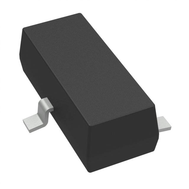
Packaged in space-saving SC-70 and SOT-23-3 and
requiring a minimum current of 45 μA (typ), the
LM4041 also is ideal for portable applications. The
TO-92 package also is available for through-hole
packaging needs. The LM4041xI is characterized for
operation over an ambient temperature range of –
40°C to 85°C. The LM4041xQ is characterized for
operation over an ambient temperature range of –
40°C to 125°C.
Data-Acquisition Systems
Power Supplies and Power-Supply Monitors
Instrumentation and Test Equipment
Process Control
Precision Audio
Automotive Electronics
Energy Management/Metering
Battery-Powered Equipment
1.2 V . . . DBZ (SOT-23) PACKAGE
(TOP VIEW)
CATHODE
1
ANODE
3 *
CATHODE 3
* Pin 3 must be connected to
ANODE or left open.
Adjustable . . . DBZ (SOT-23) PACKAGE
(TOP VIEW)
CATHODE
3
5
NC
4
NC
NC − No internal connection
* Pin 2 must be connected to
ANODE or left open.
Adjustable . . . DCK (SC-70) PACKAGE
(TOP VIEW)
NC 1
1
2
1
* 2
ANODE 2
FB
1.2 V . . . DCK (SC-70) PACKAGE
(TOP VIEW)
ANODE
ANODE
5 FB
1.2 V . . . LP (TO-92/TO-226) PACKAGE
(TOP VIEW)
ANODE
CATHODE
NC
NC − No internal connection
Adjustable . . . LP (TO-92/TO-226) PACKAGE
(TOP VIEW)
ANODE
2
CATHODE 3
CATHODE
4 NC
FB
NC − No internal connection
An IMPORTANT NOTICE at the end of this data sheet addresses availability, warranty, changes, use in safety-critical applications,
Submit Document Feedback
Copyright
© 2020 Texas
Instruments
Incorporated
intellectual
property
matters
and other important disclaimers. PRODUCTION DATA.
Product Folder Links: LM4041
1
�LM4041
www.ti.com
SLCS146F – FEBRUARY 2005 – REVISED SEPTEMBER 2020
4 Functional Block Diagram
CATHODE
+
_
VREF(1)
(2)
FB(1)
(2)
ANODE
(1) LM4041x (ADJ) only
(2) LM4041x12 only
Figure 4-1. Functional Block Diagram
5 Absolute Maximum Ratings
over free-air temperature range (unless otherwise noted)
MIN
VZ
Continuous cathode voltage
IZ
Continuous cathode current
θJA
TJ
Operating virtual junction temperature
Tstg
Storage temperature range
(1)
(2)
(3)
2
Package thermal impedance(2) (3)
–10
MAX (1)
V
25
mA
DBZ package
206
DCK package
252
LP package
156
–65
UNIT
15
°C/W
150
°C
150
°C
Stresses beyond those listed under "absolute maximum ratings" may cause permanent damage to the device. These are stress ratings
only, and functional operation of the device at these or any other conditions beyond those indicated under "recommended operating
conditions" is not implied. Exposure to absolute-maximum-rated conditions for extended periods may affect device reliability.
Maximum power dissipation is a function of TJ(max), θJA, and TA. The maximum allowable power dissipation at any allowable ambient
temperature is PD = (TJ(max) – TA)/θJA. Operating at the absolute maximum TJ of 150°C can affect reliability.
The package thermal impedance is calculated in accordance with JESD 51-7.
Submit Document Feedback
Copyright © 2020 Texas Instruments Incorporated
Product Folder Links: LM4041
�LM4041
www.ti.com
SLCS146F – FEBRUARY 2005 – REVISED SEPTEMBER 2020
6 Recommended Operating Conditions
IZ
Cathode current
VZ
Reverse breakdown voltage (adjustable version)
TA
(1)
Free-air temperature
MIN
MAX
(1)
12
mA
10
V
LM4041 (I temperature)
–40
85
LM4041 (Q temperature)
–40
125
UNIT
°C
See parametric tables
7 LM4041x12I Electrical Characteristics
full-range TA = –40°C to 85°C (unless otherwise noted)
PARAMETER
VZ
TEST CONDITIONS
Reverse breakdown
voltage
IZ = 100 μA
Reverse breakdown
voltage tolerance
IZ = 100 μA
IZ,min
Minimum cathode
current
αVZ
Average temperature
coefficient of reverse
breakdown voltage
TYP
MAX
1.225
–1.2
1.2
–2.4
2.4
9.2
–10.4
10.4
45
45
80
25°C
±20
25°C
±15
±15
25°C
0.7
Full range
mV
μA
±20
±15
±100
ppm/°C
±15
1.5
0.7
2
4
75
80
±100
25°C
25°C
75
UNIT
V
–9.2
Full range
1 mA < IZ < 12 mA
TYP
25°C
Full range
IZ,min < IZ < 1 mA
MIN
Full range
25°C
IZ = 1 mA
LM4041B12I
MAX
1.225
Full range
IZ = 100 μA
ΔVZ/ΔIZ
LM4041A12I
MIN
25°C
IZ = 10 mA
Reverse breakdown
voltage change with
cathode current change
TA
6
1.5
2
4
8
6
mV
8
ZZ
Reverse dynamic
impedance
IZ = 1 mA, f = 120 Hz,
IAC = 0.1 IZ
25°C
0.5
eN
Wideband noise
IZ = 100 μA,
10 Hz ≤ f ≤ 10 kHz
25°C
20
20
μVRMS
Long-term stability of
reverse breakdown
voltage
t = 1000 h,
TA = 25°C ± 0.1°C,
IZ = 100 μA
25°C
120
120
ppm
1.5
0.5
1.5
Ω
Submit Document Feedback
Copyright © 2020 Texas Instruments Incorporated
Product Folder Links: LM4041
3
�LM4041
www.ti.com
SLCS146F – FEBRUARY 2005 – REVISED SEPTEMBER 2020
8 LM4041x12I Electrical Characteristics
full-range TA = –40°C to 85°C (unless otherwise noted)
PARAMETER
VZ
TEST CONDITIONS
Reverse breakdown
voltage
IZ = 100 μA
Reverse breakdown
voltage tolerance
IZ = 100 μA
IZ,min
Minimum cathode
current
αVZ
Average temperature
coefficient of reverse
breakdown voltage
4
TYP
MAX
1.225
–12
12
Full range
–14
14
–24
24
45
45
80
25°C
±20
25°C
±15
±15
25°C
0.7
Full range
mV
μA
±20
±15
±150
ppm/°C
±15
1.5
0.7
2
2.5
75
80
±100
25°C
25°C
75
UNIT
V
6
Full range
1 mA < IZ < 12 mA
TYP
–6
Full range
IZ,min < IZ < 1 mA
MIN
25°C
Full range
IZ = 1 mA
LM4041D12I
MAX
1.225
25°C
IZ = 100 μA
ΔVZ/ΔIZ
LM4041C12I
MIN
25°C
IZ = 10 mA
Reverse breakdown
voltage change with
cathode current change
TA
6
2
2.5
2.5
8
8
mV
10
ZZ
Reverse dynamic
impedance
IZ = 1 mA, f = 120 Hz,
IAC = 0.1 IZ
25°C
0.5
eN
Wideband noise
IZ = 100 μA,
10 Hz ≤ f ≤ 10 kHz
25°C
20
20
μVRMS
Long-term stability of
reverse breakdown
voltage
t = 1000 h,
TA = 25°C ± 0.1°C,
IZ = 100 μA
25°C
120
120
ppm
Submit Document Feedback
1.5
0.5
2
Ω
Copyright © 2020 Texas Instruments Incorporated
Product Folder Links: LM4041
�LM4041
www.ti.com
SLCS146F – FEBRUARY 2005 – REVISED SEPTEMBER 2020
9 LM4041x12Q Electrical Characteristics
full-range TA = –40°C to 125°C (unless otherwise noted)
PARAMETER
VZ
TEST CONDITIONS
Reverse breakdown
voltage
IZ = 100 μA
Reverse breakdown
voltage tolerance
IZ = 100 μA
IZ,min
Minimum cathode
current
αVZ
Average temperature
coefficient of reverse
breakdown voltage
25°C
Full range
TYP
MAX
1.225
12
–18.4
18.4
–31
31
45
±20
25°C
±15
±15
25°C
0.7
Full range
mV
μA
±20
±15
±150
ppm/°C
±15
1.5
0.7
2
2.5
75
80
±100
25°C
25°C
45
80
25°C
25°C
75
UNIT
V
–12
Full range
1 mA < IZ < 12 mA
TYP
6
Full range
IZ,min < IZ < 1 mA
MIN
–6
Full range
IZ = 1 mA
LM4041D12Q
MAX
1.225
25°C
IZ = 100 μA
ΔVZ/ΔIZ
LM4041C12Q
MIN
25°C
IZ = 10 mA
Reverse breakdown
voltage change with
cathode current change
TA
6
2.5
2.5
8
0.5
2
8
mV
10
0.5
ZZ
Reverse dynamic
impedance
IZ = 1 mA, f = 120 Hz,
IAC = 0.1 IZ
eN
Wideband noise
IZ = 100 μA,
10 Hz ≤ f ≤ 10 kHz
25°C
20
20
μVRMS
Long-term stability of
reverse breakdown
voltage
t = 1000 h,
TA = 25°C ± 0.1°C,
IZ = 100 μA
25°C
120
120
ppm
Full range
1.5
2
Ω
Submit Document Feedback
Copyright © 2020 Texas Instruments Incorporated
Product Folder Links: LM4041
5
�LM4041
www.ti.com
SLCS146F – FEBRUARY 2005 – REVISED SEPTEMBER 2020
10 LM4041xI (Adjustable Version) Electrical Characteristics
full-range TA = –40°C to 85°C (unless otherwise noted)
PARAMETER
VREF
Reference voltage
Reference voltage
tolerance(1)
IZ,min
Minimum cathode
current
ΔVREF/ΔIZ
Reference voltage
change with cathode
current change
ΔVREF/ΔVKA
Reference voltage
change with output
voltage change
IFB
Feedback current
αVREF
Average temperature
coefficient of
reference voltage(1)
TEST CONDITIONS
IZ = 100 μA, VZ = 5 V
IZ = 100 μA, VZ = 5 V
eN
(1)
6
LM4041BI
MIN
25°C
TYP
1 mA < IZ < 12 mA
1.233
MAX
1.233
6.2
Full range
–10.5
10.5
–14
14
45
25°C
0.7
1.5
2
4
0.7
2
–2
Full range
100
–1.55
±20
25°C
±15
Full range
4
mV
–2
–2.5
60
120
25°C
μA
6
–2.5
60
mV
1.5
2
6
–1.55
75
80
2
Full range
25°C
45
80
Full range
25°C
75
UNIT
V
–6.2
Full range
IZ = 1 mA, VZ = 5 V
TYP
2.5
25°C
IZ = 1 mA
MIN
–2.5
Full range
IZ,min < IZ < 1 mA
LM4041CI
MAX
25°C
25°C
IZ = 10 mA, VZ = 5 V
ZZ
TA
100
120
mV/V
nA
±20
±15
±100
±100
ppm/°C
IZ = 100 μA, VZ = 5 V
25°C
±15
±15
IZ = 1 mA, f = 120 Hz,
IAC = 0.1 IZ, VZ = VREF
25°C
0.3
0.3
IZ = 1 mA, f = 120 Hz,
IAC = 0.1 IZ, VZ = 10 V
25°C
2
2
Wideband noise
IZ = 100 μA, VZ = VREF,
10 Hz ≤ f ≤ 10 kHz
25°C
20
20
μVRMS
Long-term stability of
reverse breakdown
voltage
t = 1000 h,
TA = 25°C ± 0.1°C,
IZ = 100 μA
25°C
120
120
ppm
Reverse dynamic
impedance
Ω
Reference voltage tolerance and average temperature coefficient change with output voltage (VZ). See Typical Characteristics.
Submit Document Feedback
Copyright © 2020 Texas Instruments Incorporated
Product Folder Links: LM4041
�LM4041
www.ti.com
SLCS146F – FEBRUARY 2005 – REVISED SEPTEMBER 2020
11 LM4041xI (Adjustable Version) Electrical Characteristics
full-range TA = –40°C to 85°C (unless otherwise noted)
PARAMETER
VREF
Reference voltage
Reference voltage tolerance(1)
IZ,min
TEST CONDITIONS
IZ = 100 μA, VZ = 5 V
IZ = 100 μA, VZ = 5 V
Reference voltage change
with cathode current change
Reference voltage change
with output voltage change
IFB
Feedback current
IZ,min < IZ < 1 mA
IZ = 1 mA
ZZ
eN
(1)
Average temperature coefficient
of reference voltage(1)
1.233
Full range
–24
24
45
25°C
0.7
75
μA
2
2.5
2
Full range
25°C
mV
80
Full range
mV
6
8
–1.55
Full range
25°C
IZ = 1 mA, VZ = 5 V
V
12
25°C
UNIT
MAX
–12
–2
mV/V
–3
60
Full range
IZ = 10 mA, VZ = 5 V
αVREF
25°C
TYP
Full range
1 mA < IZ < 12 mA
ΔVREF/ΔVKA
LM4041DI
MIN
25°C
25°C
Minimum cathode current
ΔVREF/ΔIZ
TA
150
nA
200
25°C
±20
25°C
±15
Full range
±150
ppm/°C
IZ = 100 μA, VZ = 5 V
25°C
±15
IZ = 1 mA, f = 120 Hz,
IAC = 0.1 IZ, VZ = VREF
25°C
0.3
IZ = 1 mA, f = 120 Hz,
IAC = 0.1 IZ, VZ = 10 V
25°C
2
Wideband noise
IZ = 100 μA, VZ = VREF,
10 Hz ≤ f ≤ 10 kHz
25°C
20
μVRMS
Long-term stability
of reverse breakdown voltage
t = 1000 h,
TA = 25°C ± 0.1°C,
IZ = 100 μA
25°C
120
ppm
Reverse dynamic impedance
Ω
Reference voltage tolerance and average temperature coefficient change with output voltage (VZ). See Typical Characteristics.
Submit Document Feedback
Copyright © 2020 Texas Instruments Incorporated
Product Folder Links: LM4041
7
�LM4041
www.ti.com
SLCS146F – FEBRUARY 2005 – REVISED SEPTEMBER 2020
12 LM4041xQ (Adjustable Version) Electrical Characteristics
full-range TA = –40°C to 125°C (unless otherwise noted)
PARAMETER
VREF
Reference voltage
Reference voltage
tolerance(1)
IZ,min
Minimum cathode
current
ΔVREF/ΔIZ
Reference voltage
change with cathode
current change
ΔVREF/ΔVKA
Reference voltage
change with output
voltage change
IFB
Feedback current
αVREF
Average temperature
coefficient of
reference voltage(1)
TEST CONDITIONS
IZ = 100 μA, VZ = 5 V
IZ = 100 μA, VZ = 5 V
eN
(1)
8
LM4041CQ
MIN
25°C
TYP
1 mA < IZ < 12 mA
1.233
MAX
1.233
12
Full range
–18
18
–30
30
45
25°C
0.7
1.5
2
4
0.7
2
–2
Full range
100
–1.55
±20
25°C
±15
Full range
6
mV
–2.5
–4
60
120
25°C
μA
10
–3
60
mV
2
2.5
8
–1.55
75
80
2
Full range
25°C
45
80
Full range
25°C
75
UNIT
V
–12
Full range
IZ = 1 mA, VZ = 5 V
TYP
6.2
25°C
IZ = 1 mA
MIN
–6.2
Full range
IZ,min < IZ < 1 mA
LM4041DQ
MAX
25°C
25°C
IZ = 10 mA, VZ = 5 V
ZZ
TA
150
200
mV/V
nA
±20
±15
±100
±150
ppm/°C
IZ = 100 μA, VZ = 5 V
25°C
±15
±15
IZ = 1 mA, f = 120 Hz,
IAC = 0.1 IZ, VZ = VREF
25°C
0.3
0.3
IZ = 1 mA, f = 120 Hz,
IAC = 0.1 IZ, VZ = 10 V
25°C
2
2
Wideband noise
IZ = 100 μA, VZ = VREF,
10 Hz ≤ f ≤ 10 kHz
25°C
20
20
μVRMS
Long-term stability of
reverse breakdown
voltage
t = 1000 h,
TA = 25°C ± 0.1°C,
IZ = 100 μA
25°C
120
120
ppm
Reverse dynamic
impedance
Ω
Reference voltage tolerance and average temperature coefficient change with output voltage (VZ). See Typical Characteristics.
Submit Document Feedback
Copyright © 2020 Texas Instruments Incorporated
Product Folder Links: LM4041
�LM4041
www.ti.com
SLCS146F – FEBRUARY 2005 – REVISED SEPTEMBER 2020
13 Typical Characteristics
1000
0.5
IZ = 150 mA
VREF = 1.2 V
0.4
0.3
800
0.2
Noise Voltage (nV//Hz)
Reference Voltage (V)
−9.9 ppm/5C
2.7 ppm/5C
0.1
0
−0.1
21 ppm/5C
−0.2
−0.3
600
400
200
−0.4
−0.5
−40
−20
0
20
40
60
80
0
100
1
10
Temperature (5C)
3
15
2.5
10
10k
Figure 13-2. Noise Voltage vs Frequency
1.235
LM4041 (Adj)
IZ = 1 mA
1.2345
1255C
1.234
1.5
0
−5
VZ
−10
0.5
VIN (V)
5
Reference Voltage (V)
VIN
2
VZ (V)
1k
Frequency (Hz)
Figure 13-1. Temperature Drift for Different
Average Temperature Coefficients
1
100
855C
1.2335
−405C
255C
1.233
1.2325
1.232
1.2315
−15
0
−0.5
−2
2
6
10
14
18
22
−20
26
1.231
1.2305
0
2
4
6
8
10
Reverse (Output) Voltage (V)
Time (ms)
Figure 13-3. Start-Up Characteristics
Figure 13-4. Reference Voltage vs Reverse
(Output) Voltage (for Different Temperatures)
Submit Document Feedback
Copyright © 2020 Texas Instruments Incorporated
Product Folder Links: LM4041
9
�LM4041
www.ti.com
SLCS146F – FEBRUARY 2005 – REVISED SEPTEMBER 2020
100
1.235
LM4041 (Adj)
IZ = 1 mA
1.2345
90
VREF
Feedback Current (nA)
Reference Voltage (V)
1255C
855C
80
1.234
1.2335
1.233
5V
1.2325
1.232
1.2315
10 V
255C
70
−405C
60
50
40
30
20
1.231
10
0
1.2305
−40
−20
0
20
40
60
80
100
0
2
4
6
8
10
Reverse (Output) Voltage (V)
Temperature (5C)
Figure 13-5. Reference Voltage vs Temperature (for
Different Reverse Voltages)
Figure 13-6. Feedback Current vs Reverse (Output)
Voltage (for Different Temperatures)
1000
1000
LM4041 (Adj)
IZ = 1 mA
DIZ = 0.1 IZ
Tj = 255C
Capacitor
Line
100
CL = 0 mF
10
10 V
5V
Impedance (Ω)
100
Impedance (W)
LM4041 (Adj)
IZ = 1 mA
CL = 0 mF
Capacitor
Line
LM4041 (Adj)
IZ = 150 mA
DIZ = 0.1 IZ
Tj = 25°C
10 V
10
5V
CL = 1 mF
CL = 1 mF
1.23 V
1
1
2.5 V
1.23 V
2.5 V
0.1
100
1k
10k
100k
1M
0.1
100
Frequency (Hz)
10k
100k
1M
Frequency (Hz)
Figure 13-7. Output Impedance vs Frequency
10
1k
Figure 13-8. Output Impedance vs Frequency
Submit Document Feedback
Copyright © 2020 Texas Instruments Incorporated
Product Folder Links: LM4041
�LM4041
www.ti.com
SLCS146F – FEBRUARY 2005 – REVISED SEPTEMBER 2020
FB Steps (V)
(see Figure 12)
0
100
2
100
4
6
90
8
80
Reverse Current (mA)
90
80
Reverse Current (mA)
LM4041 (Adj)
VZ = 1.23 V (nominal)
70
60
50
40
30
70
60
50
40
30
20
20
10
LM4041 (Adj)
IZ = 1 mA
10
0
0
0
0
1
2
3
4
5
6
7
8
9
0.6
0.8
1
1.2
1.4
1.6
1.8
2
Figure 13-10. Reverse Characteristics and
Minumum Operating Current
Figure 13-9. Reverse Characteristics
LM4041 (Adj)
VAdj = VREF + 5 mV
1.4
1.2
Output Saturation (V)
0.4
Reverse (Output) Voltage (V)
Reverse (Output) Voltage (V)
1.6
0.2
10
−405C
1
255C
855C
0.8
1255C
0.6
0.4
0.2
0
0
1
2
3
4
5
6
7
8
9
10 11
12
Output Current (mA)
Figure 13-11. Output Saturation vs Output Current
Submit Document Feedback
Copyright © 2020 Texas Instruments Incorporated
Product Folder Links: LM4041
11
�LM4041
www.ti.com
SLCS146F – FEBRUARY 2005 – REVISED SEPTEMBER 2020
14 Application Information
RS 30 kW
VIN
LM4041-1.2
VZ
1-Hz rate
Figure 14-1. Startup Characteristics Test Circuit
IR
(+)
LM4041 (Adj)
(−)
2 V/step
V
Figure 14-2. Reverse Characteristics Test Circuit
14.1 Output Capacitor
The LM4041 does not require an output capacitor across CATHODE and ANODE for stability. However, if an
output bypass capacitor is desired, the LM4041 is designed to be stable with all capacitive loads.
14.2 SOT-23 and SC-70 Pin Connections
There is a parasitic Schottky diode connected between pins 2 and 3 of the SOT-23 packaged device. Thus, pin 3
of the SOT-23 package must be left floating or connected to pin 2. Similarly, pin 2 of the SC-70 package also
must be left floating or connected to pin 1.
12
Submit Document Feedback
Copyright © 2020 Texas Instruments Incorporated
Product Folder Links: LM4041
�LM4041
www.ti.com
SLCS146F – FEBRUARY 2005 – REVISED SEPTEMBER 2020
14.3 Adjustable Version
The adjustable version allows VZ to be set by a user-defined resistor divider. The output voltage, VZ, is set
according to the equation shown in Figure 14-3.
VS
RS
ǒ
VREF
LM4041
Ǔ
VZ = VREF 1 ) R2
R1
+
R1
−
(Adjustable)
R2
Figure 14-3. Adjustable Shunt Regulator
14.4 Cathode and Load Currents
In a typical shunt regulator configuration (see Figure 14-4), an external resistor, RS, is connected between the
supply and the cathode of the LM4041. RS must be set properly, as it sets the total current available to supply
the load (IL) and bias the LM4041 (IZ). In all cases, IZ must stay within a specified range for proper operation of
the reference. Taking into consideration one extreme in the variation of the load and supply voltage (maximum IL
and minimum VS), RS must be small enough to supply the minimum IZ required for operation of the regulator, as
given by data sheet parameters. At the other extreme, maximum VS and minimum IL, RS must be large enough
to limit IZ to less than its maximum recommended rating of 12 mA.
RS is calculated as shown in Equation 1.
RS +
ǒVS * VZǓ
(I L ) I Z)
(1)
VS
RS
IZ + IL
IL
VZ
IZ
LM4041
Figure 14-4. Shunt Regulator
Submit Document Feedback
Copyright © 2020 Texas Instruments Incorporated
Product Folder Links: LM4041
13
�LM4041
www.ti.com
SLCS146F – FEBRUARY 2005 – REVISED SEPTEMBER 2020
15 Revision History
NOTE: Page numbers for previous revisions may differ from page numbers in the current version.
Changes from Revision E (February 2006) to Revision F (September 2020)
Page
• Updated the numbering format for tables, figures and cross-references throughout the document...................1
• Deleted Ordering Information table. See Mechanical, Packaging, and Orderable Information at the end of the
data sheet........................................................................................................................................................... 2
14
Submit Document Feedback
Copyright © 2020 Texas Instruments Incorporated
Product Folder Links: LM4041
�www.ti.com
LM4041
SLCS146F – FEBRUARY 2005 – REVISED SEPTEMBER 2020
16 Mechanical, Packaging, and Orderable Information
The following pages include mechanical, packaging, and orderable information. This information is the most
current data available for the designated devices. This data is subject to change without notice and revision of
this document. For browser-based versions of this data sheet, refer to the left-hand navigation.
Submit Document Feedback
Copyright © 2020 Texas Instruments Incorporated
Product Folder Links: LM4041
15
�PACKAGE OPTION ADDENDUM
www.ti.com
9-Aug-2022
PACKAGING INFORMATION
Orderable Device
Status
(1)
Package Type Package Pins Package
Drawing
Qty
Eco Plan
(2)
Lead finish/
Ball material
MSL Peak Temp
Op Temp (°C)
Device Marking
(3)
Samples
(4/5)
(6)
LM4041A12IDBZR
ACTIVE
SOT-23
DBZ
3
3000
RoHS & Green
NIPDAU
Level-1-260C-UNLIM
-40 to 85
(4MK3, 4MKU)
Samples
LM4041A12IDBZRG4
ACTIVE
SOT-23
DBZ
3
3000
RoHS & Green
NIPDAU
Level-1-260C-UNLIM
-40 to 85
(4MK3, 4MKU)
Samples
LM4041A12IDBZT
ACTIVE
SOT-23
DBZ
3
250
RoHS & Green
NIPDAU
Level-1-260C-UNLIM
-40 to 85
(4MK3, 4MKU)
Samples
LM4041A12IDCKR
ACTIVE
SC70
DCK
5
3000
RoHS & Green
NIPDAU
Level-1-260C-UNLIM
-40 to 85
MKU
Samples
LM4041B12IDBZR
ACTIVE
SOT-23
DBZ
3
3000
RoHS & Green
NIPDAU
Level-1-260C-UNLIM
-40 to 85
(4ML3, 4MLU)
Samples
LM4041B12IDBZT
ACTIVE
SOT-23
DBZ
3
250
RoHS & Green
NIPDAU
Level-1-260C-UNLIM
-40 to 85
(4ML3, 4MLU)
Samples
LM4041B12IDCKR
ACTIVE
SC70
DCK
5
3000
RoHS & Green
NIPDAU
Level-1-260C-UNLIM
-40 to 85
MLU
Samples
LM4041BIDBZR
ACTIVE
SOT-23
DBZ
3
3000
RoHS & Green
NIPDAU
Level-1-260C-UNLIM
-40 to 85
(4MG3, 4MGU)
Samples
LM4041BIDBZT
ACTIVE
SOT-23
DBZ
3
250
RoHS & Green
NIPDAU
Level-1-260C-UNLIM
-40 to 85
(4MG3, 4MGU)
Samples
LM4041BIDCKR
ACTIVE
SC70
DCK
5
3000
RoHS & Green
NIPDAU
Level-1-260C-UNLIM
-40 to 85
MGU
Samples
LM4041BIDCKT
ACTIVE
SC70
DCK
5
250
RoHS & Green
NIPDAU
Level-1-260C-UNLIM
-40 to 85
MGU
Samples
LM4041C12IDBZR
ACTIVE
SOT-23
DBZ
3
3000
RoHS & Green
NIPDAU
Level-1-260C-UNLIM
-40 to 85
(4MM3, 4MMU)
Samples
LM4041C12IDBZRG4
ACTIVE
SOT-23
DBZ
3
3000
RoHS & Green
NIPDAU
Level-1-260C-UNLIM
-40 to 85
(4MM3, 4MMU)
Samples
LM4041C12IDBZT
ACTIVE
SOT-23
DBZ
3
250
RoHS & Green
NIPDAU
Level-1-260C-UNLIM
-40 to 85
(4MM3, 4MMU)
Samples
LM4041C12IDCKR
ACTIVE
SC70
DCK
5
3000
RoHS & Green
NIPDAU
Level-1-260C-UNLIM
-40 to 85
MMU
Samples
LM4041C12IDCKRE4
ACTIVE
SC70
DCK
5
3000
RoHS & Green
NIPDAU
Level-1-260C-UNLIM
-40 to 85
MMU
Samples
LM4041C12IDCKRG4
ACTIVE
SC70
DCK
5
3000
RoHS & Green
NIPDAU
Level-1-260C-UNLIM
-40 to 85
MMU
Samples
LM4041C12ILP
ACTIVE
TO-92
LP
3
1000
RoHS & Green
SN
N / A for Pkg Type
-40 to 85
NPC12I
Samples
LM4041C12ILPR
ACTIVE
TO-92
LP
3
2000
RoHS & Green
SN
N / A for Pkg Type
-40 to 85
NPC12I
Samples
LM4041C12QDBZR
ACTIVE
SOT-23
DBZ
3
3000
RoHS & Green
NIPDAU
Level-1-260C-UNLIM
-40 to 125
(4MS3, 4MSU)
Samples
Addendum-Page 1
�PACKAGE OPTION ADDENDUM
www.ti.com
9-Aug-2022
Orderable Device
Status
(1)
Package Type Package Pins Package
Drawing
Qty
Eco Plan
(2)
Lead finish/
Ball material
MSL Peak Temp
Op Temp (°C)
Device Marking
(3)
Samples
(4/5)
(6)
LM4041C12QDBZT
ACTIVE
SOT-23
DBZ
3
250
RoHS & Green
NIPDAU
Level-1-260C-UNLIM
-40 to 125
(4MS3, 4MSU)
Samples
LM4041CIDBZR
ACTIVE
SOT-23
DBZ
3
3000
RoHS & Green
NIPDAU
Level-1-260C-UNLIM
-40 to 85
(4MH3, 4MHU)
Samples
LM4041CIDBZT
ACTIVE
SOT-23
DBZ
3
250
RoHS & Green
NIPDAU
Level-1-260C-UNLIM
-40 to 85
(4MH3, 4MHU)
Samples
LM4041CIDCKR
ACTIVE
SC70
DCK
5
3000
RoHS & Green
NIPDAU
Level-1-260C-UNLIM
-40 to 85
MHU
Samples
LM4041CIDCKT
ACTIVE
SC70
DCK
5
250
RoHS & Green
NIPDAU
Level-1-260C-UNLIM
-40 to 85
MHU
Samples
LM4041CILP
ACTIVE
TO-92
LP
3
1000
RoHS & Green
SN
N / A for Pkg Type
-40 to 85
NPCI
Samples
LM4041CILPE3
ACTIVE
TO-92
LP
3
1000
RoHS & Green
SN
N / A for Pkg Type
-40 to 85
NPCI
Samples
LM4041CILPR
ACTIVE
TO-92
LP
3
2000
RoHS & Green
SN
N / A for Pkg Type
-40 to 85
NPCI
Samples
LM4041CQDBZR
ACTIVE
SOT-23
DBZ
3
3000
RoHS & Green
NIPDAU
Level-1-260C-UNLIM
-40 to 125
(4MP3, 4MPU)
Samples
LM4041CQDBZT
ACTIVE
SOT-23
DBZ
3
250
RoHS & Green
NIPDAU
Level-1-260C-UNLIM
-40 to 125
(4MP3, 4MPU)
Samples
LM4041D12IDBZR
ACTIVE
SOT-23
DBZ
3
3000
RoHS & Green
NIPDAU
Level-1-260C-UNLIM
-40 to 85
(4MN3, 4MNU)
Samples
LM4041D12IDBZRG4
ACTIVE
SOT-23
DBZ
3
3000
RoHS & Green
NIPDAU
Level-1-260C-UNLIM
-40 to 85
(4MN3, 4MNU)
Samples
LM4041D12IDBZT
ACTIVE
SOT-23
DBZ
3
250
RoHS & Green
NIPDAU
Level-1-260C-UNLIM
-40 to 85
(4MN3, 4MNU)
Samples
LM4041D12IDCKR
ACTIVE
SC70
DCK
5
3000
RoHS & Green
NIPDAU
Level-1-260C-UNLIM
-40 to 85
MNU
Samples
LM4041D12ILP
ACTIVE
TO-92
LP
3
1000
RoHS & Green
SN
N / A for Pkg Type
-40 to 85
NPD12I
Samples
LM4041D12ILPE3
ACTIVE
TO-92
LP
3
1000
RoHS & Green
SN
N / A for Pkg Type
-40 to 85
NPD12I
Samples
LM4041D12ILPR
ACTIVE
TO-92
LP
3
2000
RoHS & Green
SN
N / A for Pkg Type
-40 to 85
NPD12I
Samples
LM4041D12QDBZR
ACTIVE
SOT-23
DBZ
3
3000
RoHS & Green
NIPDAU
Level-1-260C-UNLIM
-40 to 125
(4MT3, 4MTU)
Samples
LM4041DIDBZR
ACTIVE
SOT-23
DBZ
3
3000
RoHS & Green
NIPDAU
Level-1-260C-UNLIM
-40 to 85
(4MJ3, 4MJU)
Samples
LM4041DIDBZRG4
ACTIVE
SOT-23
DBZ
3
3000
RoHS & Green
NIPDAU
Level-1-260C-UNLIM
-40 to 85
(4MJ3, 4MJU)
Samples
LM4041DIDBZT
ACTIVE
SOT-23
DBZ
3
250
RoHS & Green
NIPDAU
Level-1-260C-UNLIM
-40 to 85
(4MJ3, 4MJU)
Samples
Addendum-Page 2
�PACKAGE OPTION ADDENDUM
www.ti.com
9-Aug-2022
Orderable Device
Status
(1)
Package Type Package Pins Package
Drawing
Qty
Eco Plan
(2)
Lead finish/
Ball material
MSL Peak Temp
Op Temp (°C)
Device Marking
(3)
Samples
(4/5)
(6)
LM4041DIDCKR
ACTIVE
SC70
DCK
5
3000
RoHS & Green
NIPDAU
Level-1-260C-UNLIM
-40 to 85
MJU
Samples
LM4041DILP
ACTIVE
TO-92
LP
3
1000
RoHS & Green
SN
N / A for Pkg Type
-40 to 85
NPDI
Samples
LM4041DILPR
ACTIVE
TO-92
LP
3
2000
RoHS & Green
SN
N / A for Pkg Type
-40 to 85
NPDI
Samples
LM4041DQDBZR
ACTIVE
SOT-23
DBZ
3
3000
RoHS & Green
NIPDAU
Level-1-260C-UNLIM
-40 to 125
(4MR3, 4MRU)
Samples
LM4041DQDBZRG4
ACTIVE
SOT-23
DBZ
3
3000
RoHS & Green
NIPDAU
Level-1-260C-UNLIM
-40 to 125
(4MR3, 4MRU)
Samples
LM4041DQDBZT
ACTIVE
SOT-23
DBZ
3
250
RoHS & Green
NIPDAU
Level-1-260C-UNLIM
-40 to 125
(4MR3, 4MRU)
Samples
(1)
The marketing status values are defined as follows:
ACTIVE: Product device recommended for new designs.
LIFEBUY: TI has announced that the device will be discontinued, and a lifetime-buy period is in effect.
NRND: Not recommended for new designs. Device is in production to support existing customers, but TI does not recommend using this part in a new design.
PREVIEW: Device has been announced but is not in production. Samples may or may not be available.
OBSOLETE: TI has discontinued the production of the device.
(2)
RoHS: TI defines "RoHS" to mean semiconductor products that are compliant with the current EU RoHS requirements for all 10 RoHS substances, including the requirement that RoHS substance
do not exceed 0.1% by weight in homogeneous materials. Where designed to be soldered at high temperatures, "RoHS" products are suitable for use in specified lead-free processes. TI may
reference these types of products as "Pb-Free".
RoHS Exempt: TI defines "RoHS Exempt" to mean products that contain lead but are compliant with EU RoHS pursuant to a specific EU RoHS exemption.
Green: TI defines "Green" to mean the content of Chlorine (Cl) and Bromine (Br) based flame retardants meet JS709B low halogen requirements of