LM45
www.ti.com
SNIS117C – AUGUST 1999 – REVISED FEBRUARY 2013
LM45 SOT-23 Precision Centigrade Temperature Sensors
Check for Samples: LM45
FEATURES
DESCRIPTION
•
•
•
•
•
•
•
•
•
•
•
The LM45 series are precision integrated-circuit
temperature sensors, whose output voltage is linearly
proportional to the Celsius (Centigrade) temperature.
The LM45 does not require any external calibration or
trimming to provide accuracies of ±2°C at room
temperature and ±3°C over a full −20 to +100°C
temperature range. Low cost is assured by trimming
and calibration at the wafer level. The LM45's low
output impedance, linear output, and precise inherent
calibration make interfacing to readout or control
circuitry especially easy. It can be used with a single
power supply, or with plus and minus supplies. As it
draws only 120 μA from its supply, it has very low
self-heating, less than 0.2°C in still air. The LM45 is
rated to operate over a −20° to +100°C temperature
range.
1
2
Calibrated Directly in ° Celsius (Centigrade)
Linear + 10.0 mV/°C Scale Factor
±3°C Accuracy Guaranteed
Rated for Full −20° to +100°C Range
Suitable for Remote Applications
Low Cost Due to Wafer-Llevel Trimming
Operates from 4.0V to 10V
Less than 120 μA Current Drain
Low Self-Heating, 0.20°C in Still Air
Nonlinearity Only ±0.8°C Max Over Temp
Low Impedance Output, 20Ω for 1 mA Load
APPLICATIONS
•
•
•
•
•
•
•
•
•
Battery Management
FAX Machines
Printers
Portable Medical Instruments
HVAC
Power Supply Modules
Disk Drives
Computers
Automotive
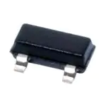
Connection Diagram
Figure 1. SOT-23
Top View
Package Number DBZ0003A
1
2
Please be aware that an important notice concerning availability, standard warranty, and use in critical applications of
Texas Instruments semiconductor products and disclaimers thereto appears at the end of this data sheet.
All trademarks are the property of their respective owners.
PRODUCTION DATA information is current as of publication date.
Products conform to specifications per the terms of the Texas
Instruments standard warranty. Production processing does not
necessarily include testing of all parameters.
Copyright © 1999–2013, Texas Instruments Incorporated
�LM45
SNIS117C – AUGUST 1999 – REVISED FEBRUARY 2013
www.ti.com
Typical Applications
Figure 2. Basic Centigrade Temperature Sensor (+2.5°C to +100°C)
Choose R1 = −VS/50 μA
VOUT = (10 mV/°C × Temp °C)
VOUT = +1,000 mV at +100°C
= +250 mV at +25°C
= −200 mV at −20°C
Figure 3. Full-Range Centigrade Temperature Sensor (−20°C to +100°C)
These devices have limited built-in ESD protection. The leads should be shorted together or the device placed in conductive foam
during storage or handling to prevent electrostatic damage to the MOS gates.
Absolute Maximum Ratings (1)
Supply Voltage
+12V to −0.2V
Output Voltage
+V S + 0.6V to −1.0V
Output Current
10 mA
−65°C to +150°C
Storage Temperature
ESD Susceptibility (2)
Human Body Model
Machine Model
(1)
(2)
2000V
250V
Absolute Maximum Ratings indicate limits beyond which damage to the device may occur. DC and AC electrical specifications do not
apply when operating the device beyond its rated operating conditions.
Human body model, 100 pF discharged through a 1.5 kΩ resistor. Machine model, 200 pF discharged directly into each pin.
Operating Ratings (1) (2) (3)
Specified Temperature Range (4)
TMIN to TMAX
−20°C to +100°C
LM45B, LM45C
Operating Temperature Range
−40°C to +125°C
LM45B, LM45C
Supply Voltage Range (+VS)
(1)
(2)
(3)
(4)
2
+4.0V to +10V
Absolute Maximum Ratings indicate limits beyond which damage to the device may occur. DC and AC electrical specifications do not
apply when operating the device beyond its rated operating conditions.
Soldering process must comply with Reflow Temperature Profile specifications. Refer to http://www.ti.com/packaging.
Reflow temperature profiles are different for lead-free and non-lead-free packages.
Thermal resistance of the SOT-23 package is 260°C/W, junction to ambient when attached to a printed circuit board with 2 oz. foil as
shown in Figure 15.
Submit Documentation Feedback
Copyright © 1999–2013, Texas Instruments Incorporated
Product Folder Links: LM45
�LM45
www.ti.com
SNIS117C – AUGUST 1999 – REVISED FEBRUARY 2013
Electrical Characteristics
Unless otherwise noted, these specifications apply for +VS = +5Vdc and ILOAD = +50 μA, in the circuit of Figure 3. These
specifications also apply from +2.5°C to TMAX in the circuit of Figure 2 for +VS = +5Vdc. Boldface limits apply for TA = T J =
TMIN to TMAX ; all other limits TA = TJ = +25°C, unless otherwise noted.
Parameter
Conditions
LM45B
Typical
Accuracy (2)
LM45C
Limit (1)
Typical
Limit (1)
T A=+25°C
±2.0
±3.0
T A=TMAX
±3.0
±4.0
T A=TMIN
±3.0
±4.0
Nonlinearity (3)
T MIN≤TA≤TMAX
±0.8
±0.8
Sensor Gain (Average Slope)
T MIN≤TA≤TMAX
Load Regulation (4)
0≤I L≤ +1 mA
Line Regulation (4)
+4.0V≤+V S≤+10V
Quiescent Current (5)
Change of Quiescent Current (5)
Minimum Temperature for Rated
Accuracy
Long Term Stability
(1)
(2)
(3)
(4)
(5)
(6)
(6)
+9.7
mV/°C (min)
+10.3
mV/°C (max)
mV/mA (max)
±35
±0.80
±1.2
±1.2
+4.0V≤+V S≤+10V, +25°C
120
120
+4.0V≤+V S≤+10V
160
160
4.0V≤+V S≤10V
2.0
2.0
+2.0
T J=TMAX, for 1000 hours
+2.5
±0.12
mV/V (max)
μA (max)
μA (max)
μA/°C
+2.0
+2.5
±0.12
°C (max)
+9.7
±35
In circuit of Figure 2, IL=0
°C (max)
+10.3
±0.80
Temperature Coefficient of
Quiescent Current
Units
(Limit)
°C (min)
°C
Limits are guaranteed to TI's AOQL (Average Outgoing Quality Level).
Accuracy is defined as the error between the output voltage and 10 mv/°C times the device's case temperature, at specified conditions
of voltage, current, and temperature (expressed in °C).
Nonlinearity is defined as the deviation of the output-voltage-versus-temperature curve from the best-fit straight line, over the device's
rated temperature range.
Regulation is measured at constant junction temperature, using pulse testing with a low duty cycle. Changes in output due to heating
effects can be computed by multiplying the internal dissipation by the thermal resistance.
Quiescent current is measured using the circuit of Figure 2.
For best long-term stability, any precision circuit will give best results if the unit is aged at a warm temperature, and/or temperature
cycled for at least 46 hours before long-term life test begins. This is especially true when a small (Surface-Mount) part is wave-soldered;
allow time for stress relaxation to occur.
Submit Documentation Feedback
Copyright © 1999–2013, Texas Instruments Incorporated
Product Folder Links: LM45
3
�LM45
SNIS117C – AUGUST 1999 – REVISED FEBRUARY 2013
www.ti.com
Typical Performance Characteristics
To generate these curves the LM45 was mounted to a printed circuit board as shown in Figure 15.
4
Thermal Resistance
Junction to Air
Thermal Time Constant
Figure 4.
Figure 5.
Thermal Response in Still Air
with Heat Sink (Figure 15)
Thermal Response
in Stirred Oil Bath
with Heat Sink
Figure 6.
Figure 7.
Start-Up Voltage
vs Temperature
Quiescent Current
vs Temperature
(In Circuit of Figure 2)
Figure 8.
Figure 9.
Submit Documentation Feedback
Copyright © 1999–2013, Texas Instruments Incorporated
Product Folder Links: LM45
�LM45
www.ti.com
SNIS117C – AUGUST 1999 – REVISED FEBRUARY 2013
Typical Performance Characteristics (continued)
To generate these curves the LM45 was mounted to a printed circuit board as shown in Figure 15.
Quiescent Current
vs Temperature
(In Circuit of Figure 3)
Accuracy
vs
Temperature
(Guaranteed)
Figure 10.
Figure 11.
Noise Voltage
Supply Voltage
vs Supply Current
Figure 12.
Figure 13.
Start-Up Response
Figure 14.
Submit Documentation Feedback
Copyright © 1999–2013, Texas Instruments Incorporated
Product Folder Links: LM45
5
�LM45
SNIS117C – AUGUST 1999 – REVISED FEBRUARY 2013
www.ti.com
PRINTED CIRCUIT BOARD
Printed Circuit Board Used for Heat Sink to Generate All Curves.
Figure 15. ½″ Square Printed Circuit Board with 2 oz. Foil or Similar
APPLICATIONS
The LM45 can be applied easily in the same way as other integrated-circuit temperature sensors. It can be glued
or cemented to a surface and its temperature will be within about 0.2°C of the surface temperature.
This presumes that the ambient air temperature is almost the same as the surface temperature; if the air
temperature were much higher or lower than the surface temperature, the actual temperature of the LM45 die
would be at an intermediate temperature between the surface temperature and the air temperature.
To ensure good thermal conductivity the backside of the LM45 die is directly attached to the GND pin. The lands
and traces to the LM45 will, of course, be part of the printed circuit board, which is the object whose temperature
is being measured. These printed circuit board lands and traces will not cause the LM45s temperature to deviate
from the desired temperature.
Alternatively, the LM45 can be mounted inside a sealed-end metal tube, and can then be dipped into a bath or
screwed into a threaded hole in a tank. As with any IC, the LM45 and accompanying wiring and circuits must be
kept insulated and dry, to avoid leakage and corrosion. This is especially true if the circuit may operate at cold
temperatures where condensation can occur. Printed-circuit coatings and varnishes such as Humiseal and epoxy
paints or dips are often used to insure that moisture cannot corrode the LM45 or its connections.
Temperature Rise of LM45 Due to Self-Heating (Thermal Resistance)
Still air
SOT-23
SOT-23
no heat sink*
small heat fin**
450°C/W
260°C/W
Moving air
180°C/W
Typical Applications
CAPACITIVE LOADS
Like most micropower circuits, the LM45 has a limited ability to drive heavy capacitive loads. The LM45 by itself
is able to drive 500 pF without special precautions. If heavier loads are anticipated, it is easy to isolate or
decouple the load with a resistor; see Figure 16. Or you can improve the tolerance of capacitance with a series
R-C damper from output to ground; see Figure 17.
Any linear circuit connected to wires in a hostile environment can have its performance affected adversely by
intense electromagnetic sources such as relays, radio transmitters, motors with arcing brushes, SCR transients,
etc, as its wiring can act as a receiving antenna and its internal junctions can act as rectifiers. For best results in
such cases, a bypass capacitor from VIN to ground and a series R-C damper such as 75Ω in series with 0.2 or 1
μF from output to ground, as shown in Figure 17, are often useful.
6
Submit Documentation Feedback
Copyright © 1999–2013, Texas Instruments Incorporated
Product Folder Links: LM45
�LM45
www.ti.com
SNIS117C – AUGUST 1999 – REVISED FEBRUARY 2013
Figure 16. LM45 with Decoupling from Capacitive Load
Figure 17. LM45 with R-C Damper
Figure 18. Temperature Sensor, Single Supply, −20°C to +100°C
Figure 19. 4-to-20 mA Current Source (0°C to +100°C)
Submit Documentation Feedback
Copyright © 1999–2013, Texas Instruments Incorporated
Product Folder Links: LM45
7
�LM45
SNIS117C – AUGUST 1999 – REVISED FEBRUARY 2013
www.ti.com
Figure 20. Fahrenheit Thermometer
Figure 21. Centigrade Thermometer (Analog Meter)
Figure 22. Expanded Scale Thermometer (50° to 80° Fahrenheit, for Example Shown)
8
Submit Documentation Feedback
Copyright © 1999–2013, Texas Instruments Incorporated
Product Folder Links: LM45
�LM45
www.ti.com
SNIS117C – AUGUST 1999 – REVISED FEBRUARY 2013
Figure 23. Temperature To Digital Converter (Serial Output) (+128°C Full Scale)
Figure 24. Temperature To Digital Converter (Parallel Outputs for Standard Data Bus to μP Interface)
(128°C Full Scale)
Submit Documentation Feedback
Copyright © 1999–2013, Texas Instruments Incorporated
Product Folder Links: LM45
9
�LM45
SNIS117C – AUGUST 1999 – REVISED FEBRUARY 2013
www.ti.com
* =1% or 2% film resistor
-Trim RB for VB=3.075V
-Trim RC for VC=1.955V
-Trim RA for VA=0.075V + 100mV/°C × Tambient
-Example, VA=2.275V at 22°C
Figure 25. Bar-Graph Temperature Display (Dot Mode)
Figure 26. LM45 With Voltage-To-Frequency Converter And Isolated Output
(2.5°C to +100°C; 25 Hz to 1000 Hz)
10
Submit Documentation Feedback
Copyright © 1999–2013, Texas Instruments Incorporated
Product Folder Links: LM45
�LM45
www.ti.com
SNIS117C – AUGUST 1999 – REVISED FEBRUARY 2013
Block Diagram
Submit Documentation Feedback
Copyright © 1999–2013, Texas Instruments Incorporated
Product Folder Links: LM45
11
�LM45
SNIS117C – AUGUST 1999 – REVISED FEBRUARY 2013
www.ti.com
REVISION HISTORY
Changes from Revision B (February 2013) to Revision C
•
12
Page
Changed layout of National Data Sheet to TI format .......................................................................................................... 11
Submit Documentation Feedback
Copyright © 1999–2013, Texas Instruments Incorporated
Product Folder Links: LM45
�PACKAGE OPTION ADDENDUM
www.ti.com
30-Sep-2021
PACKAGING INFORMATION
Orderable Device
Status
(1)
Package Type Package Pins Package
Drawing
Qty
Eco Plan
(2)
Lead finish/
Ball material
MSL Peak Temp
Op Temp (°C)
Device Marking
(3)
(4/5)
(6)
LM45BIM3
NRND
SOT-23
DBZ
3
1000
Non-RoHS
& Green
Call TI
Level-1-260C-UNLIM
-20 to 100
T4B
LM45BIM3/NOPB
ACTIVE
SOT-23
DBZ
3
1000
RoHS & Green
SN
Level-1-260C-UNLIM
-20 to 100
T4B
LM45BIM3X/NOPB
ACTIVE
SOT-23
DBZ
3
3000
RoHS & Green
SN
Level-1-260C-UNLIM
-20 to 100
T4B
LM45CIM3/NOPB
ACTIVE
SOT-23
DBZ
3
1000
RoHS & Green
SN
Level-1-260C-UNLIM
-20 to 100
T4C
LM45CIM3X
NRND
SOT-23
DBZ
3
3000
Non-RoHS
& Green
Call TI
Level-1-260C-UNLIM
-20 to 100
T4C
LM45CIM3X/NOPB
ACTIVE
SOT-23
DBZ
3
3000
RoHS & Green
SN
Level-1-260C-UNLIM
-20 to 100
T4C
(1)
The marketing status values are defined as follows:
ACTIVE: Product device recommended for new designs.
LIFEBUY: TI has announced that the device will be discontinued, and a lifetime-buy period is in effect.
NRND: Not recommended for new designs. Device is in production to support existing customers, but TI does not recommend using this part in a new design.
PREVIEW: Device has been announced but is not in production. Samples may or may not be available.
OBSOLETE: TI has discontinued the production of the device.
(2)
RoHS: TI defines "RoHS" to mean semiconductor products that are compliant with the current EU RoHS requirements for all 10 RoHS substances, including the requirement that RoHS substance
do not exceed 0.1% by weight in homogeneous materials. Where designed to be soldered at high temperatures, "RoHS" products are suitable for use in specified lead-free processes. TI may
reference these types of products as "Pb-Free".
RoHS Exempt: TI defines "RoHS Exempt" to mean products that contain lead but are compliant with EU RoHS pursuant to a specific EU RoHS exemption.
Green: TI defines "Green" to mean the content of Chlorine (Cl) and Bromine (Br) based flame retardants meet JS709B low halogen requirements of