LM4894
LM4894
1 Watt Fully Differential Audio Power Amplifier With Shutdown
Select
Literature Number: SNAS134H
�October 5, 2011
1 Watt Fully Differential Audio Power Amplifier With
Shutdown Select
General Description
Key Specifications
The LM4894 is a fully differential audio power amplifier primarily designed for demanding applications in mobile phones
and other portable communication device applications. It is
capable of delivering 1 watt of continuous average power to
an 8Ω BTL load with less than 1% distortion (THD+N) from a
5VDC power supply.
Boomer audio power amplifiers were designed specifically to
provide high quality output power with a minimal amount of
external components. The LM4894 does not require output
coupling capacitors or bootstrap capacitors, and therefore is
ideally suited for mobile phone and other low voltage applications where minimal power consumption is a primary requirement.
The LM4894 features a low-power consumption shutdown
mode. To facilitate this, Shutdown may be enabled by either
logic high or low depending on mode selection. Driving the
shutdown mode pin either high or low enables the shutdown
select pin to be driven in a likewise manner to enable Shutdown. Additionally, the LM4894 features an internal thermal
shutdown protection mechanism.
The LM4894 contains advanced pop & click circuitry which
eliminates noises which would otherwise occur during turn-on
and turn-off transitions.
The LM4894 is unity-gain stable and can be configured by
external gain-setting resistors.
■ Improved PSRR at 217Hz
80dB(typ)
■ Power Output at 5.0V & 1% THD
1.0W(typ)
■ Power Output at 3.3V & 1% THD
400mW(typ)
■ Shutdown Current
0.1µA(typ)
Features
■ Fully differential amplification
■ Available in space-saving packages micro SMD, MSOP,
■
■
■
■
■
■
■
■
■
and LLP
Ultra low current shutdown mode
Can drive capacitive loads up to 500pF
Improved pop & click circuitry eliminates noises during
turn-on and turn-off transitions
2.2 - 5.5V operation
No output coupling capacitors, snubber networks or
bootstrap capacitors required
Unity-gain stable
External gain configuration capability
Shutdown high or low selectivity
High CMRR
Applications
■ Mobile phones
■ PDAs
■ Portable electronic devices
Connection Diagrams
Mini Small Outline (MSOP) Package
LLP Package
20013723
Top View
Order Number LM4894MM
See NS Package Number MUB10A
20013735
Top View
Order Number LM4894LD
See NS Package Number LDA10B
Boomer® is a registered trademark of National Semiconductor Corporation.
© 2011 National Semiconductor Corporation
200137
200137 Version 9 Revision 5
www.national.com
Print Date/Time: 2011/10/05 07:59:55
LM4894 1 Watt Fully Differential Audio Power Amplifier With Shutdown Select
OBSOLETE
LM4894
�LM4894
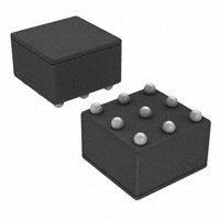
9 Bump micro SMD Package
9 Bump micro SMD Package
20013794
Top View
Order Number LM4894ITL, LM4894ITLX
See NS Package Number TLA09AAA
20013736
Top View
Order Number LM4894IBP
See NS Package Number BPA09CDB
Typical Application
20013701
FIGURE 1. Typical Audio Amplifier Application Circuit
www.national.com
2
200137 Version 9 Revision 5
Print Date/Time: 2011/10/05 07:59:55
� θJC (MSOP)
If Military/Aerospace specified devices are required,
please contact the National Semiconductor Sales Office/
Distributors for availability and specifications.
Supply Voltage
Storage Temperature
Input Voltage
Power Dissipation (Note 3)
ESD Susceptibility (Note 4)
ESD Susceptibility (Note 5)
Junction Temperature
Thermal Resistance
12°C/W
θJA (LLP)
63°C/W
Electrical Characteristics VDD = 5V
56°C/W
190°C/W
θJA (MSOP)
Soldering Information
See AN-1112 "microSMD Wafers Level Chip Scale
Package."
See AN-1187 "Leadless
Leadframe Package (LLP)."
6.0V
−65°C to +150°C
−0.3V to VDD +0.3V
Internally Limited
2000V
200V
150°C
θJC (LLP)
220°C/W
Operating Ratings
Temperature Range
TMIN ≤ TA ≤ TMAX
Supply Voltage
−40°C ≤ TA ≤ 85°C
2.2V ≤ VDD ≤ 5.5V
(Note 1, Note 2, Note 8)
The following specifications apply for VDD = 5V, AV = 1, and 8Ω load unless otherwise specified. Limits apply for TA = 25°C.
LM4894
Symbol
Parameter
Conditions
Typical
Limit
Units
(Limits)
(Note 6)
(Note 7)
IDD
Quiescent Power Supply Current
VIN = 0V, Io = 0A
4
8
mA (max)
ISD
Shutdown Current
Vshutdown = GND
0.1
1
µA (max)
Po
Output Power
THD = 1% (max); f = 1 kHz
LM4894LD, RL= 4Ω (Note 11)
LM4894, RL= 8Ω
THD+N
Total Harmonic Distortion+Noise
Po = 0.4 Wrms; f = 1kHz
PSRR
Power Supply Rejection Ratio
Vripple = 200mV sine p-p
CMRR
Common_Mode Rejection Ratio
1.4
W (min)
1
0.850
0.1
%
f = 217Hz (Note 9)
87
dB (min)
f = 1kHz (Note 9)
83
f = 217Hz (Note 10)
83
f = 1kHz (Note 10)
80
f = 217Hz
50
Electrical Characteristics VDD = 3V
63
dB
(Note 1, Note 2, Note 8)
The following specifications apply for VDD = 3V, AV = 1, and 8Ω load unless otherwise specified. Limits apply for TA = 25°C.
LM4894
Symbol
Parameter
Conditions
Units
(Limits)
Typical
Limit
(Note 6)
(Note 7)
3.5
6
mA (max)
1
µA (max)
IDD
Quiescent Power Supply Current
VIN = 0V, Io = 0A
ISD
Shutdown Current
Vshutdown = GND
0.1
Po
Output Power
THD = 1% (max); f = 1kHz
0.35
W
THD+N
Total Harmonic Distortion+Noise
Po = 0.25Wrms; f = 1kHz
0.325
%
PSRR
Power Supply Rejection Ratio
Vripple = 200mV sine p-p
f = 217Hz (Note 9)
87
dB
f = 1kHz (Note 9)
83
f = 217Hz (Note 10)
80
f = 1kHz (Note 10)
78
f = 217Hz
49
CMRR
Common-Mode Rejection Ratio
3
200137 Version 9 Revision 5
Print Date/Time: 2011/10/05 07:59:55
dB
www.national.com
LM4894
θJA (micro SMD)
Absolute Maximum Ratings (Note 2)
�LM4894
Note 1: All voltages are measured with respect to the ground pin, unless otherwise specified.
Note 2: Absolute Maximum Ratings indicate limits beyond which damage to the device may occur. Operating Ratings indicate conditions for which the device is
functional, but do not guarantee specific performance limits. Electrical Characteristics state DC and AC electrical specifications under particular test conditions
which guarantee specific performance limits. This assumes that the device is within the Operating Ratings. Specifications are not guaranteed for parameters
where no limit is given, however, the typical value is a good indication of device performance.
Note 3: The maximum power dissipation must be derated at elevated temperatures and is dictated by TJMAX, θJA, and the ambient temperature TA. The maximum
allowable power dissipation is PDMAX = (TJMAX–TA)/θJA or the number given in Absolute Maximum Ratings, whichever is lower. For the LM4894, see power derating
currents for additional information.
Note 4: Human body model, 100pF discharged through a 1.5kΩ resistor.
Note 5: Machine Model, 220pF–240pF discharged through all pins.
Note 6: Typicals are measured at 25°C and represent the parametric norm.
Note 7: Datasheet min/max specification limits are guaranteed by design, test, or statistical analysis.
Note 8: For micro SMD only, shutdown current is measured in a Normal Room Environment. Exposure to direct sunlight will increase ISD by a maximum of 2µA.
Note 9: Unterminated input.
Note 10: 10Ω terminated input.
Note 11: When driving 4Ω loads from a 5V supply, the LM4894LD must be mounted to a circuit board.
External Components Description
(Figure 1)
Components
Functional Description
1.
Ri
Inverting input resistance which sets the closed-loop gain in conjunction with Rf.
2.
Rf
Feedback resistance which sets the closed-loop gain in conjunction with Ri.
3.
CS
Supply bypass capacitor which provides power supply filtering. Refer to the Power Supply Bypassing section for
information concerning proper placement and selection of the supply bypass capacitor.
4.
CB
Bypass pin capacitor which provides half-supply filtering. Refer to the section, Proper Selection of External
Components, for information concerning proper placement and selection of CB.
www.national.com
4
200137 Version 9 Revision 5
Print Date/Time: 2011/10/05 07:59:55
�LM4894
Typical Performance Characteristics
LD Specific Characteristics
LM4894LD
THD+N vs Frequency
VDD = 5V, 4Ω RL, and Power = 1W
LM4894LD
THD+N vs Output Power
VDD = 5V, 4Ω RL
20013790
20013791
LM4894LD
Power Dissipation vs
Output Power
LM4894LD
Power Derating Curve
20013793
20013792
5
200137 Version 9 Revision 5
Print Date/Time: 2011/10/05 07:59:55
www.national.com
�LM4894
Typical Performance Characteristics
Non-LD Specific Characteristics
THD+N vs Frequency
at VDD = 5V, 8Ω RL, and PWR = 400mW
THD+N vs Frequency
at VDD = 3V, 8Ω RL, and PWR = 250mW
20013737
20013738
THD+N vs Frequency
at VDD = 3V, 4Ω RL, and PWR = 225mW
THD+N vs Frequency
at VDD = 2.6V, 8Ω RL, and PWR = 150mW
20013739
www.national.com
20013740
6
200137 Version 9 Revision 5
Print Date/Time: 2011/10/05 07:59:55
�LM4894
THD+N vs Frequency
@ VDD = 2.6V, 4Ω RL, and PWR = 150mW
THD+N vs Output Power
@ VDD = 5V, 8Ω RL
20013741
20013742
THD+N vs Output Power
@ VDD = 3V, 8Ω RL
THD+N vs Output Power
@ VDD = 3V, 4Ω RL
20013743
20013744
7
200137 Version 9 Revision 5
Print Date/Time: 2011/10/05 07:59:55
www.national.com
�LM4894
THD+N vs Output Power
@ VDD = 2.6V, 8Ω RL
THD+N vs Output Power
@ VDD = 2.6V, 4Ω RL
20013745
20013773
Power Supply Rejection Ratio (PSRR) @ VDD = 5V
Input 10Ω Terminated
Power Supply Rejection Ratio (PSRR) @ VDD = 5V
Input Floating
20013746
20013747
www.national.com
8
200137 Version 9 Revision 5
Print Date/Time: 2011/10/05 07:59:55
�Power Supply Rejection Ratio (PSRR) @ VDD = 3V
Input Floating
20013748
20013749
Output Power vs
Supply Voltage
Output Power vs
Supply Voltage
20013751
20013750
9
200137 Version 9 Revision 5
Print Date/Time: 2011/10/05 07:59:55
www.national.com
LM4894
Power Supply Rejection Ratio (PSRR) @ VDD = 3V
Input 10Ω Terminated
�LM4894
Power Dissipation vs
Output Power
Power Dissipation vs
Output Power
20013753
20013752
Power Dissipation vs
Output Power
Output Power vs
Load Resistance
20013755
20013754
Supply Current vs Shutdown Voltage
Shutdown Low
Supply Current vs Shutdown Voltage
Shutdown High
20013769
www.national.com
20013756
10
200137 Version 9 Revision 5
Print Date/Time: 2011/10/05 07:59:55
�LM4894
Clipping (Dropout) Voltage vs
Supply Voltage
Open Loop Frequency Response
20013784
20013774
Power Derating Curve
Noise Floor
20013776
20013777
Input CMRR vs
Frequency
Input CMRR vs
Frequency
20013778
20013779
11
200137 Version 9 Revision 5
Print Date/Time: 2011/10/05 07:59:55
www.national.com
�LM4894
PSRR vs
DC Common-Mode Voltage
PSRR vs
DC Common-Mode Voltage
20013780
20013781
THD vs
Common-Mode Voltage
THD vs
Common-Mode Voltage
20013782
www.national.com
20013783
12
200137 Version 9 Revision 5
Print Date/Time: 2011/10/05 07:59:55
�DIFFERENTIAL AMPLIFIER EXPLANATION
The LM4894 is a fully differential audio amplifier that features
differential input and output stages. Internally this is accomplished by two circuits: a differential amplifier and a common
mode feedback amplifier that adjusts the output voltages so
that the average value remains VDD/2. When setting the differential gain, the amplifier can be considered to have
"halves". Each half uses an input and feedback resistor
(Ri1and RF1) to set its respective closed-loop gain (see Figure
1). With Ri1 = Ri2 and RF1 = RF2, the gain is set at -RF/Ri for
each half. This results in a differential gain of
AVD = -RF/Ri
(1)
It is extremely important to match the input resistors to each
other, as well as the feedback resistors to each other for best
amplifier performance. See the Proper Selection of External Components section for more information. A differential
amplifier works in a manner where the difference between the
two input signals is amplified. In most applications, this would
require input signals that are 180° out of phase with each other. The LM4894 can be used, however, as a single ended
input amplifier while still retaining its fully differential benefits.
In fact, completely unrelated signals may be placed on the
input pins. The LM4894 simply amplifies the difference between them. Figures 2 and 3 show single-ended applications
of the LM4894 that still take advantage of the differential nature of the amplifier and the benefits to PSRR, common-mode
noise reduction, and "click and pop" reduction.
All of these applications, either single-ended or fully differential, provide what is known as a "bridged mode" output
(bridge-tied-load, BTL). This results in output signals at Vo1
and Vo2 that are 180° out of phase with respect to each other.
Bridged mode operation is different from the single-ended
amplifier configuration that connects the load between the
amplifier output and ground. A bridged amplifier design has
distinct advantages over the single-ended configuration: it
provides differential drive to the load, thus doubling maximum
possible output swing for a specific supply voltage. Four times
the output power is possible compared with a single-ended
amplifier under the same conditions. This increase in attainable output power assumes that the amplifier is not current
limited or clipped. In order to choose an amplifier's closedloop gain without causing excess clipping, please refer to the
Audio Power Amplifier Design section.
A bridged configuration, such as the one used in the LM4894,
also creates a second advantage over single-ended amplifiers. Since the differential outputs, Vo1 and Vo2, are biased at
half-supply, no net DC voltage exists across the load. This
assumes that the input resistor pair and the feedback resistor
pair are properly matched (see Proper Selection of External
Components). BTL configuration eliminates the output coupling capacitor required in single-supply, single-ended amplifier configurations. If an output coupling capacitor is not used
in a single-ended output configuration, the half-supply bias
across the load would result in both increased internal IC
power dissipation as well as permanent loudspeaker damage. Further advantages of bridged mode operation specific
to fully differential amplifiers like the LM4894 include increased power supply rejection ratio, common-mode noise
reduction, and click and pop reduction.
PCB LAYOUT AND SUPPLY REGULATION
CONSIDERATIONS FOR DRIVING 3Ω AND 4Ω LOADS
Power dissipated by a load is a function of the voltage swing
across the load and the load's impedance. As load impedance
decreases, load dissipation becomes increasingly de-pendent on the interconnect (PCB trace and wire) resistance
between the amplifier output pins and the load's connections.
Residual trace resistance causes a voltage drop, which results in power dissipated in the trace and not in the load as
desired. For example, 0.1Ω trace resistance reduces the output power dissipated by a 4Ω load from 1.4W to 1.37W. This
problem of decreased load dissipation is exacerbated as load
impedance decreases. Therefore, to maintain the highest
load dissipation and widest output voltage swing, PCB traces
that connect the output pins to a load must be as wide as
possible.
Poor power supply regulation adversely affects maximum
output power. A poorly regulated supply's output voltage decreases with increasing load current. Reduced supply voltage
causes decreased headroom, output signal clipping, and reduced output power. Even with tightly regulated supplies,
trace resistance creates the same effects as poor sup-ply
regulation. Therefore, making the power supply traces as
wide as possible helps maintain full output voltage swing.
13
200137 Version 9 Revision 5
Print Date/Time: 2011/10/05 07:59:55
www.national.com
LM4894
EXPOSED-DAP PACKAGE PCB MOUNTING
CONSIDERATIONS
The LM4894's exposed-DAP (die attach paddle) package
(LD) provide a low thermal resistance between the die and
the PCB to which the part is mounted and soldered. This allows rapid heat transfer from the die to the surrounding PCB
copper traces, ground plane and, finally, surrounding air. The
result is a low voltage audio power amplifier that produces
1.4W at ≤ 1% THD with a 4Ω load. This high power is
achieved through careful consideration of necessary thermal
design. Failing to optimize thermal design may compromise
the LM4894's high power performance and activate unwanted, though necessary, thermal shutdown protection. The LD
package must have its DAP soldered to a copper pad on the
PCB. The DAP's PCB copper pad is connected to a large
plane of continuous unbroken copper. This plane forms a
thermal mass and heat sink and radiation area. Place the heat
sink area on either outside plane in the case of a two-sided
PCB, or on an inner layer of a board with more than two layers.
Connect the DAP copper pad to the inner layer or backside
copper heat sink area with 4 (2x2) vias. The via diameter
should be 0.012in - 0.013in with a 0.050in pitch. Ensure efficient thermal conductivity by plating-through and solder-filling
the vias.
Best thermal performance is achieved with the largest practical copper heat sink area. If the heatsink and amplifier share
the same PCB layer, a nominal 2.5in2 (min) area is necessary
for 5V operation with a 4Ω load. Heatsink areas not placed on
the same PCB layer as the LM4894 should be 5in2 (min) for
the same supply voltage and load resistance. The last two
area recommendations apply for 25°C ambient temperature.
In all circumstances and conditions, the junction temperature
must be held below 150°C to prevent activating the LM4894's
thermal shutdown protection. The LM4894's power de-rating
curve in the Typical Performance Characteristics shows the
maximum power dissipation versus temperature. Example
PCB layouts for the exposed-DAP TSSOP and LLP packages
are shown in the Demonstration Board Layout section. Further detailed and specific information concerning PCB layout,
fabrication, and mounting an LLP package is available from
National Semiconductor's package Engineering Group under
application note AN1187.
Application Information
�LM4894
lection is thus dependant upon desired PSRR and click and
pop performance as explained in the section Proper Selection of External Components.
POWER DISSIPATION
Power dissipation is a major concern when designing a successful amplifer, whether the amplifier is bridged or singleended. Equation 2 states the maximum power dissipation
point for a single-ended amplifier operating at a given supply
voltage and driving a specified output load.
PDMAX=(VDD)2/(2π2RL) Single-Ended
SHUTDOWN FUNCTION
In order to reduce power consumption while not in use, the
LM4894 contains shutdown circuitry that is used to turn off the
amplifier's bias circuitry. In addition, the LM4894 contains a
Shutdown Mode pin, allowing the designer to designate
whether the part will be driven into shutdown with a high level
logic signal or a low level logic signal. This allows the designer
maximum flexibility in device use, as the Shutdown Mode pin
may simply be tied permanently to either VDD or GND to set
the LM4894 as either a "shutdown-high" device or a "shutdown-low" device, respectively. The device may then be
placed into shutdown mode by toggling the Shutdown Select
pin to the same state as the Shutdown Mode pin. For
simplicity's sake, this is called "shutdown same", as the
LM4894 enters shutdown mode whenever the two pins are in
the same logic state. The trigger point for either shutdown
high or shutdown low is shown as a typical value in the Supply
Current vs Shutdown Voltage graphs in the Typical Performance Characteristics section. It is best to switch between
ground and supply for maximum performance. While the device may be disabled with shutdown voltages in between
ground and supply, the idle current may be greater than the
typical value of 0.1µA. In either case, the shutdown pin should
be tied to a definite voltage to avoid unwanted state changes.
In many applications, a microcontroller or microprocessor
output is used to control the shutdown circuitry, which provides a quick, smooth transition to shutdown. Another solution
is to use a single-throw switch in conjunction with an external
pull-up resistor (or pull-down, depending on shutdown high or
low application). This scheme guarantees that the shutdown
pin will not float, thus preventing unwanted state changes.
(2)
However, a direct consequence of the increased power delivered to the load by a bridge amplifier is an increase in
internal power dissipation versus a single-ended amplifier operating at the same conditions.
PDMAX = 4*(VDD)2/(2π2RL) Bridge Mode
(3)
Since the LM4894 has bridged outputs, the maximum internal
power dissipation is 4 times that of a single-ended amplifier.
Even with this substantial increase in power dissipation, the
LM4894 does not require additional heatsinking under most
operating conditions and output loading. From Equation 3,
assuming a 5V power supply and an 8Ω load, the maximum
power dissipation point is 625mW. The maximum power dissipation point obtained from Equation 3 must not be greater
than the power dissipation results from Equation 4:
PDMAX = (TJMAX - TA)/θJA
(4)
The LM4894's θJA in an MUA10A package is 190°C/W. Depending on the ambient temperature, TA, of the system surroundings, Equation 4 can be used to find the maximum
internal power dissipation supported by the IC packaging. If
the result of Equation 3 is greater than that of Equation 4, then
either the supply voltage must be decreased, the load
impedance increased, the ambient temperature reduced, or
the θJA reduced with heatsinking. In many cases, larger traces
near the output, VDD, and GND pins can be used to lower the
θJA. The larger areas of copper provide a form of heatsinking
allowing higher power dissipation. For the typical application
of a 5V power supply, with an 8Ω load, the maximum ambient
temperature possible without violating the maximum junction
temperature is approximately 30°C provided that device operation is around the maximum power dissipation point. Recall that internal power dissipation is a function of output
power. If typical operation is not around the maximum power
dissipation point, the LM4894 can operate at higher ambient
temperatures. Refer to the Typical Performance Characteristics curves for power dissipation information.
PROPER SELECTION OF EXTERNAL COMPONENTS
Proper selection of external components in applications using
integrated power amplifiers is critical when optimizing device
and system performance. Although the LM4894 is tolerant to
a variety of external component combinations, consideration
of component values must be made when maximizing overall
system quality.
The LM4894 is unity-gain stable, giving the designer maximum system flexibility. The LM4894 should be used in low
closed-loop gain configurations to minimize THD+N values
and maximize signal to noise ratio. Low gain configurations
require large input signals to obtain a given output power. Input signals equal to or greater than 1Vrms are available from
sources such as audio codecs. Please refer to the Audio
Power Amplifier Design section for a more complete explanation of proper gain selection. When used in its typical
application as a fully differential power amplifier the LM4894
does not require input coupling capacitors for input sources
with DC common-mode voltages of less than VDD. Exact allowable input common-mode voltage levels are actually a
function of VDD, Ri, and Rf and may be determined by Equation 5:
POWER SUPPLY BYPASSING
As with any power amplifier, proper supply bypassing is critical for low noise performance and high power supply rejection ratio (PSRR). The capacitor location on both the bypass
and power supply pins should be as close to the device as
possible. A larger half-supply bypass capacitor improves
PSRR because it increases half-supply stability. Typical applications employ a 5V regulator with 10µF and 0.1µF bypass
capacitors that increase supply stability. This, however, does
not eliminate the need for bypassing the supply nodes of the
LM4894. Although the LM4894 will operate without the bypass capacitor CB, although the PSRR may decrease. A 1µF
capacitor is recommended for CB. This value maximizes
PSRR performance. Lesser values may be used, but PSRR
decreases at frequencies below 1kHz. The issue of CB sewww.national.com
VCMi


 工商网监
湘ICP备2023018690号
工商网监
湘ICP备2023018690号
