LM837
www.ti.com
SNOSBZ6C – MAY 1999 – REVISED MARCH 2013
LM837 Low Noise Quad Operational Amplifier
Check for Samples: LM837
FEATURES
DESCRIPTION
•
•
The LM837 is a quad operational amplifier designed
for low noise, high speed and wide bandwidth
performance. It has a new type of output stage which
can drive a 600Ω load, making it ideal for almost all
digital audio, graphic equalizer, preamplifiers, and
professional audio applications. Its high performance
characteristics
also
make
it
suitable
for
instrumentation applications where low noise is the
key consideration.
1
2
•
•
•
•
•
•
High Slew Rate 10 V/μs (typ); 8 V/μs (min)
Wide Gain Bandwidth Product 25 MHz (typ); 15
MHz (min)
Power Bandwidth 200 kHz (typ)
High Output Current ±40 mA
Excellent Output Drive Performance >600Ω
Low Input Noise Voltage 4.5 nV/√Hz
Low Total Harmonic Distortion 0.0015%
Low Offset Voltage 0.3 mV
The LM837 is internally compensated for unity gain
operation. It is pin compatible with most other
standard quad op amps and can therefore be used to
upgrade existing systems with little or no change.
Schematic and Connection Diagrams
Figure 1. PDIP Package
Top View
See Package Number
D0014A or NFF0014A
1
2
Please be aware that an important notice concerning availability, standard warranty, and use in critical applications of
Texas Instruments semiconductor products and disclaimers thereto appears at the end of this data sheet.
All trademarks are the property of their respective owners.
PRODUCTION DATA information is current as of publication date.
Products conform to specifications per the terms of the Texas
Instruments standard warranty. Production processing does not
necessarily include testing of all parameters.
Copyright © 1999–2013, Texas Instruments Incorporated
�LM837
SNOSBZ6C – MAY 1999 – REVISED MARCH 2013
www.ti.com
These devices have limited built-in ESD protection. The leads should be shorted together or the device placed in conductive foam
during storage or handling to prevent electrostatic damage to the MOS gates.
ABSOLUTE MAXIMUM RATINGS (1) (2)
Supply Voltage, VCC/VEE
±18V
Differential Input Voltage, VID (3)
±30V
Common Mode Input Voltage, VIC (3)
±15V
Power Dissipation, PD
(4)
1.2W (N)
830 mW (M)
−40°C to +85°C
Operating Temperature Range, TOPR
−60°C to +150°C
Storage Temperature Range, TSTG
Soldering Information
PDIP Package
Soldering (10 seconds)
260°C
SOIC Package
Vapor Phase (60 seconds)
215°C
Infrared (15 seconds)
220°C
ESD rating to be determined.
See http://www.ti.com for other methods of soldering surface mount devices.
(1)
Absolute Maximum Ratings indicate limits beyond which damage to the device may occur. Operating Ratings indicate conditions for
which the device is functional, but do not ensure specific performance limits. Electrical Characteristics state DC and AC electrical
specifications under particular test conditions which ensure specific performance limits. This assumes that the device is within the
Operating Ratings. Specifications are not specified for parameters where no limit is given, however, the typical value is a good indication
of device performance.
If Military/Aerospace specified devices are required, please contact the Texas Instruments Sales Office/Distributors for availability and
specifications.
Unless otherwise specified the absolute maximum input voltage is equal to the power supply voltage.
For operation at ambient temperatures above 25°C, the device must be derated based on a 150°C maximum junction temperature and a
thermal resistance, junction to ambient, as follows: LM837N, 90°C/W; LM837M, 150°C/W.
(2)
(3)
(4)
DC ELECTRICAL CHARACTERISTICS
TA = 25°C, VS = ±15V
Symbol
Parameter
Condition
Min
RS = 50Ω
Typ
Max
Units
0.3
5
mV
10
200
nA
500
1000
nA
VOS
Input Offset Voltage
IOS
Input Offset Current
IB
Input Bias Current
AV
Large Signal Voltage Gain
RL = 2 kΩ, VOUT = ±10V
90
110
dB
VOM
Output Voltage Swing
RL = 2 kΩ
±12
±13.5
V
RL = 600Ω
±10
±12.5
V
VCM
Common Mode Input Voltage
±12
±14.0
V
CMRR
Common Mode Rejection Ratio
VIN = ±12V
80
100
dB
PSRR
Power Supply Rejection Ratio
VS = 15 ∼ 5, −15 ∼ −5
80
100
IS
Power Supply Current
RL = ∞, Four Amps
10
dB
15
mA
AC ELECTRICAL CHARACTERISTICS
TA = 25°C, VS = ±15V
Min
Typ
SR
Symbol
Slew Rate
RL = 600Ω
8
10
V/μs
GBW
Gain Bandwidth Product
f = 100 kHz, RL = 600Ω
15
25
MHz
2
Parameter
Condition
Submit Documentation Feedback
Max
Units
Copyright © 1999–2013, Texas Instruments Incorporated
Product Folder Links: LM837
�LM837
www.ti.com
SNOSBZ6C – MAY 1999 – REVISED MARCH 2013
DESIGN ELECTRICAL CHARACTERISTICS
TA= 25°C, VS=±15V
(1)
Symbol
Parameter
Condition
Min
Typ
Max
Units
PBW
Power Bandwidth
VO = 25 VP-P, RL = 600Ω,
THD < 1%
200
kHz
en1
Equivalent Input Noise Voltage
JIS A, RS = 100Ω
0.5
μV
en2
Equivalent Input Noise Voltage
f = 1 kHz
4.5
nV/ √Hz
in
Equivalent Input Noise Current
f = 1 kHz
0.7
pA/ √Hz
THD
Total Harmonic Distortion
AV = 1, VOUT = 3 Vrms,
f = 20 ∼ 20 kHz, RL = 600Ω
0.0015
%
fU
Zero Cross Frequency
Open Loop
12
MHz
φm
Phase Margin
Open Loop
45
deg
Input-Referred Crosstalk
f = 20 ∼ 20 kHz
−120
dB
2
μV/°C
ΔVOS/Δ
T
(1)
Average TC of Input Offset Voltage
The following parameters are not tested or ensured.
Submit Documentation Feedback
Copyright © 1999–2013, Texas Instruments Incorporated
Product Folder Links: LM837
3
�LM837
SNOSBZ6C – MAY 1999 – REVISED MARCH 2013
www.ti.com
DETAILED SCHEMATIC
4
Submit Documentation Feedback
Copyright © 1999–2013, Texas Instruments Incorporated
Product Folder Links: LM837
�LM837
www.ti.com
SNOSBZ6C – MAY 1999 – REVISED MARCH 2013
TYPICAL PERFORMANCE CHARACTERISTICS
Maximum Power Dissipation vs
Ambient Temperature
Normalized Input Bias Current
vs Supply Voltage
Figure 2.
Figure 3.
Normalized Input Bias Current
vs Ambient Temperature
Supply Current vs
Supply Voltage
Figure 4.
Figure 5.
Supply Current vs
Ambient Temperature
Positive Current Limit
Figure 6.
Figure 7.
Submit Documentation Feedback
Copyright © 1999–2013, Texas Instruments Incorporated
Product Folder Links: LM837
5
�LM837
SNOSBZ6C – MAY 1999 – REVISED MARCH 2013
www.ti.com
TYPICAL PERFORMANCE CHARACTERISTICS (continued)
6
Negative Current Limit
Maximum Output Voltage
vs Supply Voltage
Figure 8.
Figure 9.
Maximum Output Voltage
vs Supply Voltage
Maximum Output Voltage
vs Ambient Temperature
Figure 10.
Figure 11.
Maximum Output Voltage
vs Ambient Temperature
Power Bandwidth
Figure 12.
Figure 13.
Submit Documentation Feedback
Copyright © 1999–2013, Texas Instruments Incorporated
Product Folder Links: LM837
�LM837
www.ti.com
SNOSBZ6C – MAY 1999 – REVISED MARCH 2013
TYPICAL PERFORMANCE CHARACTERISTICS (continued)
Normalized Slew Rate & Gain Bandwidth
vs
Supply Voltage (f = 100 kHz)
Normalized Slew Rate & Gain Bandwidth (f = 100 kHz)
vs Ambient Temperature
Figure 14.
Figure 15.
Voltage Gain
vs
Supply Voltage
Voltage Gain
vs
Ambient Temperature
Figure 16.
Figure 17.
Power Supply Rejection
vs Frequency
CMRR
vs
Frequency
Figure 18.
Figure 19.
Submit Documentation Feedback
Copyright © 1999–2013, Texas Instruments Incorporated
Product Folder Links: LM837
7
�LM837
SNOSBZ6C – MAY 1999 – REVISED MARCH 2013
www.ti.com
TYPICAL PERFORMANCE CHARACTERISTICS (continued)
8
Open Loop Gain &
Phase
vs
Frequency
Total Harmonic Distortion
vs Frequency
Figure 20.
Figure 21.
Equivalent Input Noise Voltage
vs
Frequency
Equivalent Input Noise Current
vs
Frequency
Figure 22.
Figure 23.
Small Signal, Non-Inverting
TA = 25°C, AV = 1, RL = 600Ω, VS = ±15V
Current Limit
TA = 25°C, VS = ±15V, RL = 100Ω, AV = 1
Figure 24.
Figure 25.
Submit Documentation Feedback
Copyright © 1999–2013, Texas Instruments Incorporated
Product Folder Links: LM837
�LM837
www.ti.com
SNOSBZ6C – MAY 1999 – REVISED MARCH 2013
TYPICAL PERFORMANCE CHARACTERISTICS (continued)
Large Signal Non-Inverting
TA = 25°C, RL = 600Ω, VS = ±15V
Large Signal Inverting
TA = 25°C, RL = 600Ω, VS = ±15V
Figure 26.
Figure 27.
Submit Documentation Feedback
Copyright © 1999–2013, Texas Instruments Incorporated
Product Folder Links: LM837
9
�LM837
SNOSBZ6C – MAY 1999 – REVISED MARCH 2013
www.ti.com
REVISION HISTORY
Changes from Revision B (March 2013) to Revision C
•
10
Page
Changed layout of National Data Sheet to TI format ............................................................................................................ 5
Submit Documentation Feedback
Copyright © 1999–2013, Texas Instruments Incorporated
Product Folder Links: LM837
�PACKAGE OPTION ADDENDUM
www.ti.com
10-Dec-2020
PACKAGING INFORMATION
Orderable Device
Status
(1)
Package Type Package Pins Package
Drawing
Qty
Eco Plan
(2)
Lead finish/
Ball material
MSL Peak Temp
Op Temp (°C)
Device Marking
(3)
(4/5)
(6)
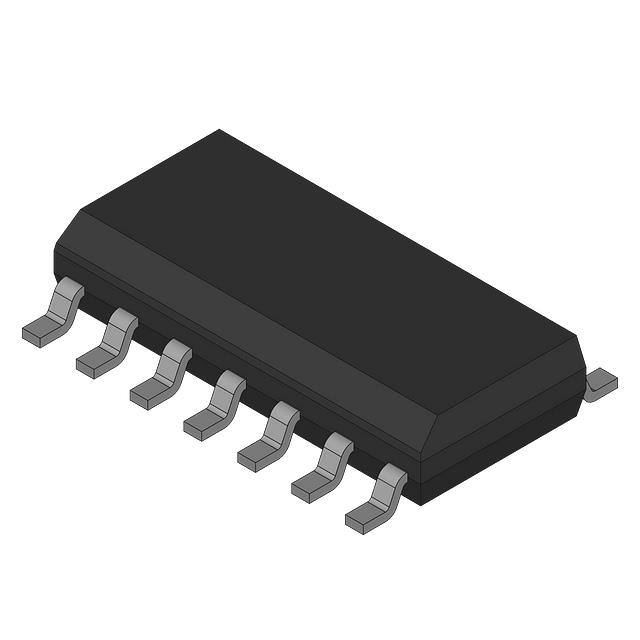
LM837MX/NOPB
ACTIVE
SOIC
D
14
2500
RoHS & Green
SN
Level-1-260C-UNLIM
-40 to 85
LM837M
(1)
The marketing status values are defined as follows:
ACTIVE: Product device recommended for new designs.
LIFEBUY: TI has announced that the device will be discontinued, and a lifetime-buy period is in effect.
NRND: Not recommended for new designs. Device is in production to support existing customers, but TI does not recommend using this part in a new design.
PREVIEW: Device has been announced but is not in production. Samples may or may not be available.
OBSOLETE: TI has discontinued the production of the device.
(2)
RoHS: TI defines "RoHS" to mean semiconductor products that are compliant with the current EU RoHS requirements for all 10 RoHS substances, including the requirement that RoHS substance
do not exceed 0.1% by weight in homogeneous materials. Where designed to be soldered at high temperatures, "RoHS" products are suitable for use in specified lead-free processes. TI may
reference these types of products as "Pb-Free".
RoHS Exempt: TI defines "RoHS Exempt" to mean products that contain lead but are compliant with EU RoHS pursuant to a specific EU RoHS exemption.
Green: TI defines "Green" to mean the content of Chlorine (Cl) and Bromine (Br) based flame retardants meet JS709B low halogen requirements of