National Semiconductor is now part of
Texas Instruments.
Search http://www.ti.com/ for the latest technical
information and details on our current products and services.
�LMP8640/LMP8640HV
Precision High Voltage Current Sense Amplifier
General Description
Features
The LMP8640 and the LMP8640HV are precision current
sense amplifiers that detect small differential voltages across
a sense resistor in the presence of high input common mode
voltages with a supply voltage range from 2.7V to 12V.
The LMP8640 accepts input signals with common mode voltage range from -2V to 42V, while the LMP8640HV accepts
input signal with common mode voltage range from -2V to
76V. The LMP8640 and LMP8640HV have fixed gain for applications that demand accuracy over temperature. The
LMP8640 and LMP8640HV come out with three different
fixed gains 20V/V, 50V/V, 100V/V ensuring a gain accuracy
as low as 0.25%. The output is buffered in order to provide
low output impedance. This high side current sense amplifier
is ideal for sensing and monitoring currents in DC or battery
powered systems, excellent AC and DC specifications over
temperature, and keeps errors in the current sense loop to a
minimum. The LMP8640 and LMP8640HV are ideal choice
for industrial, automotive and consumer applications, and it is
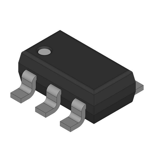
available in TSOT-6 package.
Typical values, TA = 25°C
■ High common-mode voltage range
-2V to 42V
— LMP8640
-2V to 76V
— LMP8640HV
2.7V to 12V
■ Supply voltage range
20V/V; 50V/V; 100V/V
■ Gain options
0.25%
■ Max gain error
900µV
■ Low offset voltage
13 μA
■ Input bias current
85 dB
■ PSRR
103 dB
■ CMRR (2.1V to 42V)
-40°C to 125°C
■ Temperature range
■ 6-Pin TSOT Package
Applications
■
■
■
■
■
■
High-side current sense
Vehicle current measurement
Motor controls
Battery monitoring
Remote sensing
Power management
Typical Application
30071462
LMP™ is a trademark of National Semiconductor Corporation.
© 2010 National Semiconductor Corporation
300714
www.national.com
LMP8640/LMP8640HV Precision High Voltage Current Sense Amplifier
September 7, 2010
�LMP8640/LMP8640HV
LMP8640
-6V to 60V
Voltage at VOUT pin
V- to V+
Storage Temperature Range
-65°C to 150°C
Junction Temperature (Note 3)
150°C
For soldering specifications,
see product folder at www.national.com and
www.national.com/ms/MS/MS-SOLDERING.pdf
Absolute Maximum Ratings (Note 1)
If Military/Aerospace specified devices are required,
please contact the National Semiconductor Sales Office/
Distributors for availability and specifications.
ESD Tolerance (Note 2)
Human Body Model
For input pins +IN, -IN
For all other pins
Machine Model
Charge device model
Supply Voltage (VS = V+ - V−)
Differential Voltage +IN- (-IN)
Voltage at pins +IN, -IN
LMP8640HV
5000V
2000V
200V
1250V
13.2V
6V
Operating Ratings
(Note 1)
Supply Voltage (VS = V+ - V−)
Temperature Range (Note 3)
Package Thermal Resistance(Note 3)
TSOT-6
2.7V to 12V
-40°C to 125°C
96°C/W
-6V to 80V
2.7V Electrical Characteristics
(Note 4)
Unless otherwise specified, all limits guaranteed for at TA = 25°C, VS=V+ – V-, VSENSE= +IN-(-IN), V+ = 2.7V, V− = 0V, −2V < VCM
< 76V, RL = 10MΩ. Boldface limits apply at the temperature extremes.
Symbol
Parameter
Condition
Min
Typ
Max
(Note 6) (Note 5) (Note 6)
-900
-1160
VOS
Input Offset Voltage
VCM = 2.1V
TCVOS
Input Offset Voltage Drift
(Note 7, Note 9)
VCM = 2.1V
IB
Input Bias Current (Note 10)
VCM = 2.1V
12
eni
Input Voltage Noise (Note 9)
f > 10 kHz
117
Gain AV
Fixed Gain LMP8640-T
LMP8640HV-T
20
V/V
Fixed Gain LMP8640-F
LMP8640HV-F
50
V/V
Fixed Gain LMP8640-H
LMP8640HV-H
100
V/V
Gain error
VCM = 2.1V
Accuracy over temperature
(Note 9)
−40°C to 125°C, VCM=2.1V
PSRR
Power Supply Rejection Ratio
VCM = 2.1V, 2.7V < V+ < 12V,
85
CMRR
Common Mode Rejection Ratio
LMP8640HV 2.1V < VCM < 42V
LMP8640 2.1V < VCM< 42V
103
LMP8640HV 2.1V < VCM < 76V
95
-2V 10 kHz
117
Gain AV
Fixed Gain LMP8640-T
LMP8640HV-T
20
V/V
Fixed Gain LMP8640-F
LMP8640HV-F
50
V/V
Fixed Gain LMP8640-H
LMP8640HV-H
100
V/V
Gain error
VCM = 2.1V
Accuracy over temperature
(Note 9)
−40°C to 125°C, VCM=2.1V
PSRR
Power Supply Rejection Ratio
VCM = 2.1V, 2.7V < V+ < 12V,
85
CMRR
Common Mode Rejection Ratio
LMP8640HV 2.1V < VCM < 42V
LMP8640 2.1V < VCM< 42V
103
LMP8640HV 2.1V < VCM < 76V
95
-2V
TA. Absolute Maximum Ratings indicate junction temperature limits beyond which the device may be permanently degraded, either mechanically or electrically.
Note 5: Typical values represent the most likely parametric norm at the time of characterization. Actual typical values may vary over time and will also depend
on the application and configuration. The typical values are not tested and are not guaranteed on shipped production material.
Note 6: Limits are 100% production tested at 25°C. Limits over the operating temperature range are guaranteed through correlations using statistical quality
control (SQC) method.
Note 7: Offset voltage temperature drift is determined by dividing the change in VOS at the temperature extremes by the total temperature change.
Note 8: The number specified is the average of rising and falling slew rates and measured at 90% to 10%.
Note 9: This parameter is guaranteed by design and/or characterization and is not tested in production.
Note 10: Positive Bias Current corresponds to current flowing into the device.
5
www.national.com
LMP8640/LMP8640HV
Symbol
�LMP8640/LMP8640HV
Block Diagram
30071430
Connection Diagram
6-Pin TSOT
30071402
Top View
Pin Descriptions
Pin
Name
Description
1
VOUT
Single Ended Output
2
V-
Negative Supply Voltage
3
+IN
Positive Input
4
-IN
Negative Input
5
NC
Not Connected
6
V+
Positive Supply Voltage
www.national.com
6
�Package
Gain
Part Number
Package Marking
LMP8640MK-T
LMP8640MKE-T
6-Pin TSOT
20V/V
AA6A
LMP8640MKX-T
3k Units Tape and Reel
1k Units Tape and Reel
AB6A
LMP8640HVMKX-T
50V/V
1k Units Tape and Reel
AC6A
LMP8640HVMK-F
1k Units Tape and Reel
AD6A
250 Units Tape and Reel
1k Units Tape and Reel
AE6A
250 Units Tape and Reel
LMP8640MKX-H
3k Units Tape and Reel
LMP8640HVMK-H
1k Units Tape and Reel
LMP8640HVMKE-H
MK06A
3k Units Tape and Reel
LMP8640MK-H
LMP8640MKE-H
100V/V
250 Units Tape and Reel
3k Units Tape and Reel
LMP8640HVMKX-F
6-Pin TSOT
250 Units Tape and Reel
LMP8640MKX-F
LMP8640HVMKE-F
MK06A
3k Units Tape and Reel
LMP8640MK-F
LMP8640MKE-F
NSC Drawing
250 Units Tape and Reel
LMP8640HVMK-T
LMP8640HVMKE-T
6-Pin TSOT
Transport Media
1k Units Tape and Reel
AF6A
LMP8640HVMKX-H
MK06A
250 Units Tape and Reel
3k Units Tape and Reel
7
www.national.com
LMP8640/LMP8640HV
Ordering Information
�LMP8640/LMP8640HV
Typical Performance Characteristics
Unless otherwise specified: TA = 25°C, VS=V+-V-, VSENSE= +IN -
(-IN), RL = 10 MΩ.
Supply Curent vs. Supply Voltage
Supply Current vs. VCM
30071425
30071426
Supply Current vs. VCM
Supply Current vs. VCM
30071427
30071428
CMRR vs. VCM (Gain 20V/V)
CMRR vs. VCM (Gain 50V/V)
30071423
30071422
www.national.com
8
�LMP8640/LMP8640HV
CMRR vs. VCM (Gain 100V/V)
Gain vs. Frequency
30071424
30071414
Output voltage vs. VSENSE
Output voltage vs. VSENSE (ZOOM close to 0V)
30071416
30071417
Large Step response
Small Step response
30071418
30071419
9
www.national.com
�LMP8640/LMP8640HV
Settling time (fall)
Settling time (rise)
30071420
30071421
Common mode step response (rise)
Common mode step response (fall)
30071411
30071410
Load regulation (Sinking)
Load regulation (Sourcing)
30071432
www.national.com
30071431
10
�LMP8640/LMP8640HV
AC PSRR vs. Frequency
AC CMRR vs. Frequency
30071412
30071413
11
www.national.com
�LMP8640/LMP8640HV
gested. In this condition is required to take in account also the
power rating of RS resistor. The low input offset of the
LMP8640 allows the use of small sense resistors to reduce
power dissipation still providing a good input dynamic range.
The input dynamic range is the ratio expressed in dB between
the maximum signal that can be measured and the minimum
signal that can be detected, usually the input offset is the
principal limiting factor.
Application Information
GENERAL
The LMP8640 and LMP8640HV are single supply high side
current sense amplifiers with a fixed gain of 20V/V, 50V/V,
100V/V and a common mode voltage range of -2V to 42V or
-2V to 76V depending on the grade.
THEORY OF OPERATION
As seen from the picture below, the current flowing through
RS develops a voltage drop equal to VSENSE across RS. The
high impedance inputs of the amplifier doesn’t conduct this
current and the high open loop gain of the sense amplifier
forces its non-inverting input to the same voltage as the inverting input. In this way the voltage drop across RIN matches
VSENSE. A current proportional to IS according to the following
relation:
DRIVING ADC
The input stage of an Analog to Digital converter can be modelled with a resistor and a capacitance versus ground. So if
the voltage source doesn't have a low impedance an error in
the amplitude's measurement will occur. In this case a buffer
is needed to drive the ADC. The LMP8640 has an internal
output buffer able to drive a capacitance load up to 30 pF or
the input stage of an ADC. If required an external low pass
RC filter can be added at the output of the LMP8640 to reduce
the noise and the bandwidth of the current sense.
IG = VSENSE/RIN = RS*IS/RIN ,
flows entirely in the internal gain resistor RG developing a
voltage drop equal to
VRG = IG *RG = (VSENSE/RIN) *RG = ((RS*IS)/RIN)*RG
This voltage is buffered and showed at the output with a very
low impedance allowing a very easy interface of the LMP8640
with other ICs (ADC, μC…).
VOUT = 2*(RS*IS)*G,
where G=RG/RIN = 10V/V, 25V/V, 50V/V, according to the
gain options.
30071461
FIGURE 2. LMP8640 to ADC interface
DESIGN EXAMPLE
For example in a current monitor application is required to
measure the current sunk by a load (peak current 10A) with
a resolution of 10mA and 0.5% of accuracy. The 10bit analog
to digital converter accepts a max input voltage of 4.1V. Moreover in order to not burn much power on the shunt resistor it
needs to be less than 10mΩ. In the table below are summarized the other working condition.
Working Condition
30071403
FIGURE 1. Current monitor
SELECTION OF THE SHUNT RESISTOR
The value chosen for the shunt resistor, RS, depends on the
application. It plays a big role in a current sensing system and
must be chosen with care. The selection of the shunt resistor
needs to take in account the small-signal accuracy, the power
dissipated and the voltage loss across the shunt itself. In applications where a small current is sensed, a bigger value of
RS is selected to minimize the error in the proportional output
voltage. Higher resistor value improves the SNR at the input
of the current sense amplifier and hence gives an accurate
output. Similarly when high current is sensed, the power losses in RS can be significant so a smaller value of RS is sugwww.national.com
Value
Min
Max
Supply Voltage
5V
5.5V
Common mode Voltage
48V
70V
Temperature
0°C
70°C
Signal BW
50kHz
First step – LMP8640 / LMP8640HV selection
The required common mode voltage of the application implies
that the right choice is the LMP8640HV (High common mode
voltage up tp 76V).
Second step – Gain option selection
We can choose between three gain option (20V/V, 50V/V,
100V/V). considering the max input voltage of the ADC
12
�Accuracy Calculation
ERROR SOURCE
Rs=4.1mΩ
Rs=8.1mΩ
Tc Vos
182µV
182µV
Nosie
216µV
216µV
Gain drift
75.2µV
151µV
Total error (squared sum of
contribution)
293µV
320µV
Accuracy
100*(Max_VSENSE / Total
Error)
0.7%
0.4%
From the tables above is clear that the 8.2mΩ shunt resistor
allows the respect of the project's constraints. The power
burned on the Shunt is 820mW at 10A.
Resolution Calculation
ERROR SOURCE
Rs=4.1mΩ
Rs=8.1mΩ
CMRR calibrated ad mid
VCM range
77.9µV
77.9µV
PSRR calibrated at 5V
8.9µV
8.9µV
Total error (squared sum of
contribution)
78µV
78µV
Resolution
(Total error / RS)
19.2mA
9.6mA
13
www.national.com
LMP8640/LMP8640HV
(4.1V) , the max Sense voltage across the shunt resistor is
evaluated according the following formula:
VSENSE= (MAX Vin ADC) / Gain;
hence the max VSENSE will be 205mV, 82mV, 41mV respectively. The shunt resistor are then evaluated considering the
maximum monitored current :
RS = (max VSENSE) / I_MAX
For each gain option the max shunt resistors are the following : 20.5mΩ, 8.2mΩ, 4.1mΩ respectively.
One of the project constraints requires RS


 工商网监
湘ICP备2023018690号
工商网监
湘ICP备2023018690号
