www.ti.com
Table of Contents
User’s Guide
LMZ12003 SIMPLE SWITCHER® Power Module Evaluation
Module User's Guide
Table of Contents
1 Description.............................................................................................................................................................................. 1
2 Packaging Highlights............................................................................................................................................................. 1
3 Demo Board Features.............................................................................................................................................................1
4 Typical Applications............................................................................................................................................................... 2
5 Demo Board Schematic......................................................................................................................................................... 3
6 Demo Board Bill of Materials (BOM)..................................................................................................................................... 4
7 Demo Board Hookup.............................................................................................................................................................. 4
8 Demo Board Passive Components....................................................................................................................................... 5
9 Performance Characteristics.................................................................................................................................................6
10 Revision History................................................................................................................................................................... 6
Trademarks
SIMPLE SWITCHER® is a registered trademark of Texas Instruments.
All trademarks are the property of their respective owners.
1 Description
The LMZ12003 SIMPLE SWITCHER power module is a complete, easy to use, step-down DC-DC solution
capable of driving up to 3-A load. The LMZ12003 is available in an innovative, easy-to-use package that
enhances thermal performance and allows for hand or machine soldering.
The LMZ12003 demo board can accept an input voltage rail between 4.5 V and 20 V and deliver an adjustable
and highly accurate output voltage as low as 0.8 V. The LMZ12003 only requires three external resistors and
four external capacitors to complete the power solution. The LMZ12003 is a reliable and robust solution with the
following protection features:
• Thermal shutdown
• Input under-voltage lockout (UVLO)
• Output over-voltage protection (OVP)
• Short-circuit protection
• Output current limit
• Allows start-up into a pre-biased output
A single resistor adjusts switching frequency up to 1 MHz.
2 Packaging Highlights
•
•
•
•
•
7-lead module package (similar to TO-263)
Single exposed die attach pad for enhanced thermal performance
10.2-mm × 13.8-mm × 4.6-mm module package
High power density
1.7-inch × 2.3-inch reduced size demo board form factor
3 Demo Board Features
•
•
•
•
•
•
4.5-V to 20-V power input voltage range
UVLO programmed at 4.5 V
0.8-V to 6-V adjustable output voltage range
Up to 3-A output current
Integrated shielded inductor in module
Efficiency up to 92%
SNVA427C – JANUARY 2010 – REVISED DECEMBER 2021
LMZ12003 SIMPLE SWITCHER® Power Module Evaluation Module User's
Submit Document Feedback
Guide
Copyright © 2021 Texas Instruments Incorporated
1
�Typical Applications
•
•
•
•
•
•
•
www.ti.com
All ceramic capacitor design
No loop compensation required
Starts into pre-biased loads
Short circuit protection
Thermal shutdown
Only nine external passives plus module
2-layer low-cost assembly
4 Typical Applications
•
•
•
•
•
Point-of-load conversions from 5-V and 12-V input rails
Space constrained applications
Industrial controls
Telecom
Networking equipment
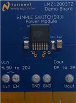
Figure 4-2. Back View
Figure 4-1. Front View
Table 4-1. Absolute Maximum Module Ratings
VIN, RON to GND
–0.3 V to 25 V
EN, FB, SS to GND
–0.3 V to 7 V
Table 4-2. Module Operating Ratings
VIN
4.5 V to 20 V
EN (Input on pin 3 module pin)
0 V to 6.5 V
Junction temperature range (TJ)
–40°C to +125°C
Table 4-3. Demo Board Operating Ratings
2
VIN
4.5 V to 20 V
VOUT (Default setting)
1.8 V
IOUT
0 A to 3 A
EN (Input on demo board post)
0 V to 20 V
LMZ12003 SIMPLE SWITCHER® Power Module Evaluation Module User's
SNVA427C – JANUARY 2010 – REVISED DECEMBER 2021
Guide
Submit Document Feedback
Copyright © 2021 Texas Instruments Incorporated
�www.ti.com
Demo Board Schematic
Table 4-3. Demo Board Operating Ratings (continued)
UVLO setting on Enable input
4.5 V
Soft-start time
2.2 mS
Operating temperature range (TJ)
–40°C to +70°C (at full 3-A load)
5 Demo Board Schematic
U1
EP
Enable
VIN
VOUT
FB
1.8VO @ 3A
7
GND
SS
6
5
VIN
EN
4
3
2
1
RON
LMZ12003TZ-ADJ
4.5V to 20V
RENT
CFF
32.4k
0.022 PF
RFBT
RON
32.4k
RENB
11.8k
CIN1
10 PF
1.87k
CSS
0.022 PF
RFBB
1.50k
CO1
CO2
1 PF
100 PF
SNVA427C – JANUARY 2010 – REVISED DECEMBER 2021
LMZ12003 SIMPLE SWITCHER® Power Module Evaluation Module User's
Submit Document Feedback
Guide
Copyright © 2021 Texas Instruments Incorporated
3
�Demo Board Bill of Materials (BOM)
www.ti.com
6 Demo Board Bill of Materials (BOM)
Table 6-1. Board Bill of Materials (BOM)
Ref Des
Description
Case
Manufacturer Part Number
Ron
32.4 kΩ 1% resistor
603
Rent
32.4 kΩ 1% resistor
603
Renb
11.8 kΩ 1% resistor
603
Rfbt
1.87 kΩ 1% resistor
603
Rfbb
1.50 kΩ 1% resistor
603
Cff
0.022-μF, 50-V, X7R ceramic
capacitor
603
Css
0.022-μF, 50-V, X7R ceramic
capacitor
603
Cin
10-μF, 50-V, X5R ceramic
capacitor
1210
UMK325BJ106MM-T
Cout1
1.0-μF, 50-V, X7R ceramic
capacitor
1206
UMK316B7105KL-T
Cout2
100-μF, 6.3-V, X5R ceramic
capacitor
1210
JMK325BJ107MM-T
U1
LMZ12003 SIMPLE SWITCHER
Power Module
TO-PMOD
LMZ12003TZ-ADJ
Alternate resistor values for alternative output voltages
VOUT
RFBT
RFBB
RON
6
2.49 k
383 Ω
124 k
5
5.62 k
1.07 k
100 k
3.3
3.32 k
1.07 k
61.9 k
2.5
2.26 k
1.07 k
47.5 k
1.8
1.87 k
1.50 k
32.4 k
1.5
1.00 k
1.13 k
28.0 k
1.2
4.22 k
8.45 k
22.6 k
0.8
0.0 K
39.2 k
24.9 k
7 Demo Board Hookup
VOUT: Connect the load to VOUT and one of the GND posts. The module can source up to a 3-A load current.
Connect VIN to a positive voltage in the 4.5-V to 20-V range. Connect the negative terminal of the source supply
to one of the posts labeled GND.
The Enable input post is configured for direct connection to the VIN post. With the chosen resistor values, this
results in an undervoltage lockout level of 4.5-V input. The top enable resistor is RENT (aka REN1) and the
bottom enable resistor is RENB (aka REN2).
If the Enable post is disconnected, the module will be disabled and about 20 μA of supply current will flow from
VIN to ground while in the disabled mode. With the enable input connected to VIN through the resistor divider,
there will be about 1.5 mA of no-load quiescent current into the VIN input. Additional current flows into the enable
divider string.
4
LMZ12003 SIMPLE SWITCHER® Power Module Evaluation Module User's
SNVA427C – JANUARY 2010 – REVISED DECEMBER 2021
Guide
Submit Document Feedback
Copyright © 2021 Texas Instruments Incorporated
�www.ti.com
Demo Board Passive Components
8 Demo Board Passive Components
Soft-start capacitor: The soft-start capacitor controls the rise time of the output voltage when power is first
applied and following the clearing of a fault mode.
Feedback divider: Regulator output voltage is programmed though the selection of the two resistors, RFBT (aka
RFB1) and RFB (aka RFB2). A feedforward capacitor (CFF) is located in parallel with the upper feedback divider
resistor. This capacitor improves the step response to abrupt changes in load current. For a different output
voltage, see Table 6-1 when modifying the board. Resistor values shown will minimize error in output voltage
setting.
RON Resistor: The primary function of the RON resistor is to set the on-time interval of the internal control
section switching cycle. The secondary function of the RON resistor is to create a nearly constant operating
frequency over the input operating voltage range. If the output voltage of the regulator is changed by adjusting
the feedback divider, then it is generally required that the RON resistor value also be changed in order to
maintain the same operating frequency.
Cout: A parallel connection of a 1-µF, 50-V and a 100-µF, 6.3-V multilayer ceramic are used for the output
capacitor. Locations are provided on the PCB assembly for experimenting with additional output capacitors..
Cin: A 10-μF, 50-V multilayer ceramic is connected as the input filter. Locations are provided on the PCB
assembly for experimenting with additional input capacitors.
SNVA427C – JANUARY 2010 – REVISED DECEMBER 2021
LMZ12003 SIMPLE SWITCHER® Power Module Evaluation Module User's
Submit Document Feedback
Guide
Copyright © 2021 Texas Instruments Incorporated
5
�Performance Characteristics
www.ti.com
9 Performance Characteristics
2.5
100
95
2
5.0
3.3
2.5
85
80
DISSIPATION (W)
EFFICIENCY (%)
90
1.8
1.5
1.2
75
70
0.8
65
5.0
3.3
2.5
1.5
1.8
1
1.5
1.2
0.8
0.5
60
25° C
55
25° C
50
0
0
0.5
1
1.5
3
2.5
2
0.5
0
1
1.5
2
2.5
3
OUTPUT CURRENT (A)
OUTPUT CURRENT(A)
Figure 9-2. Dissipation, 12 V Input at 25°C
Figure 9-1. Efficiency, 12 V Input at 25°C
OUTPUT VOLTAGE (V)
1.83
1.825
1.82
5.5
1.815
20
12
6
1.81
5
1.805
25°C
1.8
0
0.5
4.75
4.5
5.25
1
1.5
2
2.5
3
OUTPUT CURRENT (A)
Figure 9-3. Line and Load Regulation at 25°C
10 Revision History
NOTE: Page numbers for previous revisions may differ from page numbers in the current version.
Changes from Revision B (April 2013) to Revision C (December 2021)
Page
• Updated the numbering format for tables, figures, and cross-references throughout the document..................1
• Updated the user's guide title............................................................................................................................. 1
• Edited the user's guide for clarity........................................................................................................................1
6
LMZ12003 SIMPLE SWITCHER® Power Module Evaluation Module User's
SNVA427C – JANUARY 2010 – REVISED DECEMBER 2021
Guide
Submit Document Feedback
Copyright © 2021 Texas Instruments Incorporated
�IMPORTANT NOTICE AND DISCLAIMER
TI PROVIDES TECHNICAL AND RELIABILITY DATA (INCLUDING DATA SHEETS), DESIGN RESOURCES (INCLUDING REFERENCE
DESIGNS), APPLICATION OR OTHER DESIGN ADVICE, WEB TOOLS, SAFETY INFORMATION, AND OTHER RESOURCES “AS IS”
AND WITH ALL FAULTS, AND DISCLAIMS ALL WARRANTIES, EXPRESS AND IMPLIED, INCLUDING WITHOUT LIMITATION ANY
IMPLIED WARRANTIES OF MERCHANTABILITY, FITNESS FOR A PARTICULAR PURPOSE OR NON-INFRINGEMENT OF THIRD
PARTY INTELLECTUAL PROPERTY RIGHTS.
These resources are intended for skilled developers designing with TI products. You are solely responsible for (1) selecting the appropriate
TI products for your application, (2) designing, validating and testing your application, and (3) ensuring your application meets applicable
standards, and any other safety, security, regulatory or other requirements.
These resources are subject to change without notice. TI grants you permission to use these resources only for development of an
application that uses the TI products described in the resource. Other reproduction and display of these resources is prohibited. No license
is granted to any other TI intellectual property right or to any third party intellectual property right. TI disclaims responsibility for, and you
will fully indemnify TI and its representatives against, any claims, damages, costs, losses, and liabilities arising out of your use of these
resources.
TI’s products are provided subject to TI’s Terms of Sale or other applicable terms available either on ti.com or provided in conjunction with
such TI products. TI’s provision of these resources does not expand or otherwise alter TI’s applicable warranties or warranty disclaimers for
TI products.
TI objects to and rejects any additional or different terms you may have proposed. IMPORTANT NOTICE
Mailing Address: Texas Instruments, Post Office Box 655303, Dallas, Texas 75265
Copyright © 2022, Texas Instruments Incorporated
�