www.ti.com
Table of Contents
User’s Guide
LMZ21700 and LMZ21701 Power Module Evaluation
Module User's Guide
Table of Contents
1 Introduction.............................................................................................................................................................................2
2 Board Specifications.............................................................................................................................................................. 2
3 Schematic, Bill of Materials, and PCB Layout......................................................................................................................3
4 Typical Performance...............................................................................................................................................................6
5 Revision History......................................................................................................................................................................8
Trademarks
SIMPLE SWITCHER® is a registered trademark of Texas Instruments.
All trademarks are the property of their respective owners.
SNVU180B – APRIL 2014 – REVISED JANUARY 2022
Submit Document Feedback
LMZ21700 and LMZ21701 Power Module Evaluation Module User's Guide
Copyright © 2022 Texas Instruments Incorporated
1
�Introduction
www.ti.com
1 Introduction
The LMZ21701 and LMZ21700 SIMPLE SWITCHER® nano modules are easy-to-use DC-DC solutions
optimized for space constrained applications. The LMZ21701 is capable of driving up to 1-A load with excellent
power conversion efficiency, output voltage accuracy, line and load regulation, and load transient response. The
LMZ21700 is a 650-mA load current version module, pin-to-pin compatible with the LMZ21701. The evaluation
board is configured for 3.3-V output voltage from 5-V to 17-V input. The resistor voltage dividers, RFBT and RFBB,
set the output voltage. The external capacitor CSS sets the soft-start time for VOUT. See the LMZ21701 1-A
Nano Module With 17-V Maximum Input Voltage or LMZ21700 650-mA Nano Module With 17-V Maximum Input
Voltage data sheets for component selection and device details. The board features turret terminals for easy
connection to input supply, load, EN input, as well as soft start voltage and power-good flag monitoring.
2 Board Specifications
•
•
•
•
•
•
VIN = 5 V to 17 V
VOUT = 3.3 V
1-A max load (LMZ21701)
650-mA max load (LMZ21700)
4-layer PCB
4.2-cm × 4.2-cm PCB size
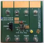
Figure 2-1. Board Top View
2
Figure 2-2. Board Top View
LMZ21700 and LMZ21701 Power Module Evaluation Module User's Guide
Copyright © 2022 Texas Instruments Incorporated
SNVU180B – APRIL 2014 – REVISED JANUARY 2022
Submit Document Feedback
�www.ti.com
Schematic, Bill of Materials, and PCB Layout
3 Schematic, Bill of Materials, and PCB Layout
OPTIONAL COMPONENT FOR CONTROL
LOOP MEASUREMENTS WITH
FREQUENCY RESPONSE ANALYZER
OPTIONAL CONNECTOR FOR TESTING THE BOARD
Figure 3-1. Evaluation Board Schematic
Table 3-1. Bill of Materials, VIN = 5 V to 17 V, VOUT = 3.3 V,
IOUT (MAX) = 1000 mA (LMZ21701), 650 mA (LMZ21700)
Designator
Description
Case Size
Manufacturer
Manufacturer P/N
Quantity
U1
SIMPLE SWITCHER Nano Module
SIL0008E
Texas Instruments
LMZ21701SIL / LMZ21700SIL
1
SNVU180B – APRIL 2014 – REVISED JANUARY 2022
Submit Document Feedback
LMZ21700 and LMZ21701 Power Module Evaluation Module User's Guide
Copyright © 2022 Texas Instruments Incorporated
3
�Schematic, Bill of Materials, and PCB Layout
www.ti.com
Table 3-1. Bill of Materials, VIN = 5 V to 17 V, VOUT = 3.3 V,
IOUT (MAX) = 1000 mA (LMZ21701), 650 mA (LMZ21700) (continued)
Designator
Description
Case Size
Manufacturer
Manufacturer P/N
Quantity
CIN
CAP, CERM, 22 µF, 25 V, ±10%,
X7R
1210
MuRata
GRM32ER71E226KE15L
1
COUT
CAP, CERM, 22 µF, 10 V, ±20%,
X5R
0805
Taiyo Yuden
LMK212BJ226MG-T
1
CSS
CAP, CERM, 3300 pF, 50 V, ±10%,
X7R
0402
MuRata
GRM155R71H332KA01D
1
J1
Header, TH, 100 mil, 1x3, Gold
plated
Samtec, Inc
TSW-103-07-G-S
1
Rfbb
RES, 383 kΩ, 1%, 0.063 W
0402
Vishay-Dale
CRCW0402383KFKED
1
Rfbt
RES, 1.21 MΩ, 1%, 0.063 W
0402
Vishay-Dale
CRCW04021M21FKED
1
Rpg
RES, 10.0 kΩ, 1%, 0.063 W
0402
Vishay-Dale
CRCW040210K0FKED
1
Rs
RES, 10.0 Ω, 1%, 0.063 W
0402
Vishay-Dale
CRCW040210R0FKED
1
SH-J1
Shunt, 100 mil, Gold plated, Black
Samtec, Inc
SNT-100-BK-G
1
TT1-12
Terminal, Turret, TH, Double
Keystone Electronics
1502-2
8
Vout S+
Test Point, TH, Miniature, Yellow
Keystone Electronics
5004
1
Figure 3-2. Evaluation Board Top Layer
4
Figure 3-3. Evaluation Board Mid Layer 1
LMZ21700 and LMZ21701 Power Module Evaluation Module User's Guide
SNVU180B – APRIL 2014 – REVISED JANUARY 2022
Submit Document Feedback
Copyright © 2022 Texas Instruments Incorporated
�www.ti.com
Schematic, Bill of Materials, and PCB Layout
Figure 3-4. Evaluation Board Mid Layer 2
Figure 3-5. Evaluation Board Bottom Layer
SNVU180B – APRIL 2014 – REVISED JANUARY 2022
Submit Document Feedback
LMZ21700 and LMZ21701 Power Module Evaluation Module User's Guide
Copyright © 2022 Texas Instruments Incorporated
5
�Typical Performance
www.ti.com
4 Typical Performance
100
0.6
VIN=4.5V
VIN=5V
VIN=9V
VIN=12V
VIN=15V
VIN=17V
POWER DISSIPATION (W)
90
EFFICIENCY (%)
80
70
60
50
40
VIN=4.5V
VIN=5V
VIN=9V
VIN=12V
VIN=15V
VIN=17V
30
20
10
0
0.0
0.1
0.2
0.3
0.4
0.5
0.6
0.7
0.8
0.9
0.4
0.3
0.2
0.1
0.0
1.0
LOAD CURRENT (A)
0.5
0.0
3.306
0.2
0.3
0.4
3.302
3.300
0.6
0.7
0.8
0.9
1.0
C001
Figure 4-2. Power Dissipation
VIN=4.5V
VIN=5V
VIN=9V
VIN=12V
VIN=15V
VIN=17V
3.304
0.5
LOAD CURRENT (A)
Figure 4-1. Efficiency
OUTPUT VOLTAGE (V)
0.1
C001
ILOAD 500mA/Div
3.298
3.296
VOUT 20mV/Div AC
3.294
3.292
3.290
0.0
0.1
0.2
0.3
0.4
0.5
0.6
0.7
0.8
0.9
LOAD CURRENT (A)
1.0
1ms/Div
20MHz BW
Figure 4-4. Load Transient
C001
Figure 4-3. Line and Load Regulation
WITH 500MHz SCOPE BANDWIDTH
COUT2 = 3x1000pF 0805 NP0
Johanson Dielectrics 500R15N102JV4T
Taiyo Yuden MK212BJ226MG-T
50mV/Div
10mV/Div
20MHz BW
1µs/Div
Figure 4-5. Output Voltage Ripple (20-MHz Scope
BW)
6
COUT1 = 22 F 10V 0805 X5R
Taiyo Yuden MK212BJ226MG-T
VOUT RIPPLE
VOUT RIPPLE
COUT = 22 F 10V 0805 X5R
500MHz BW
1µs/Div
Figure 4-6. Output Voltage Ripple and HF Noise
(500-MHz Scope BW)
LMZ21700 and LMZ21701 Power Module Evaluation Module User's Guide
Copyright © 2022 Texas Instruments Incorporated
SNVU180B – APRIL 2014 – REVISED JANUARY 2022
Submit Document Feedback
�www.ti.com
Typical Performance
80
VOUT 1V/Div
PGOOD 2V/Div
ENABLE 500mV/Div
Radiated Emissions (dBµV/m)
ILOAD 500mA/Div
Evaluation Board
EN 55022 Class B Limit
EN 55022 Class A Limit
70
60
50
40
30
20
10
1ms/Div
20MHz BW
0
0
Figure 4-7. Start-Up
200
400
600
Frequency (MHz)
800
1000
D002
Figure 4-8. LMZ21700 Radiated EMI (Default BOM),
VIN = 12 V, VOUT = 3.3 V, IOUT = 650 mA
100
Evaluation Board
EN 55022 Class B Limit
EN 55022 Class A Limit
70
Peak Emissions
Quasi Peak Limit
Average Limit
90
Conducted Emissions (dBµV)
Radiated Emissions (dBµV/m)
80
60
50
40
30
20
10
80
70
60
50
40
30
20
10
0
0
200
400
600
Frequency (MHz)
800
1000
0
0.1
1
Figure 4-9. LMZ21701 Radiated EMI (Default BOM),
VIN = 12 V, VOUT = 3.3 V, IOUT = 1000 mA
10
100
Frequency (MHz)
D004
D001
Figure 4-10. LMZ21700 Conducted EMI (1 µF, 2.2
µH Input Filter), VIN = 12 V, VOUT = 3.3 V, IOUT = 650
mA
100
Peak Emissions
Quasi Peak Limit
Average Limit
Conducted Emissions (dBµV)
90
80
70
60
50
40
30
20
10
0
0.1
1
10
Frequency (MHz)
100
D003
Figure 4-11. LMZ21701 Conducted EMI (1 µF, 2.2 µH Additional Input Filter), VIN = 12 V, VOUT = 3.3 V, IOUT
= 1000 mA
SNVU180B – APRIL 2014 – REVISED JANUARY 2022
Submit Document Feedback
LMZ21700 and LMZ21701 Power Module Evaluation Module User's Guide
Copyright © 2022 Texas Instruments Incorporated
7
�Revision History
www.ti.com
5 Revision History
NOTE: Page numbers for previous revisions may differ from page numbers in the current version.
Changes from Revision A (October 2014) to Revision B (January 2022)
Page
• Updated the numbering format for tables, figures, and cross-references throughout the document. ................2
• Updated the user's guide title ............................................................................................................................ 2
Changes from Revision * (April 2014) to Revision A (October 2014)
Page
• Added SVA cleanup and editing......................................................................................................................... 6
8
LMZ21700 and LMZ21701 Power Module Evaluation Module User's Guide
Copyright © 2022 Texas Instruments Incorporated
SNVU180B – APRIL 2014 – REVISED JANUARY 2022
Submit Document Feedback
�IMPORTANT NOTICE AND DISCLAIMER
TI PROVIDES TECHNICAL AND RELIABILITY DATA (INCLUDING DATA SHEETS), DESIGN RESOURCES (INCLUDING REFERENCE
DESIGNS), APPLICATION OR OTHER DESIGN ADVICE, WEB TOOLS, SAFETY INFORMATION, AND OTHER RESOURCES “AS IS”
AND WITH ALL FAULTS, AND DISCLAIMS ALL WARRANTIES, EXPRESS AND IMPLIED, INCLUDING WITHOUT LIMITATION ANY
IMPLIED WARRANTIES OF MERCHANTABILITY, FITNESS FOR A PARTICULAR PURPOSE OR NON-INFRINGEMENT OF THIRD
PARTY INTELLECTUAL PROPERTY RIGHTS.
These resources are intended for skilled developers designing with TI products. You are solely responsible for (1) selecting the appropriate
TI products for your application, (2) designing, validating and testing your application, and (3) ensuring your application meets applicable
standards, and any other safety, security, regulatory or other requirements.
These resources are subject to change without notice. TI grants you permission to use these resources only for development of an
application that uses the TI products described in the resource. Other reproduction and display of these resources is prohibited. No license
is granted to any other TI intellectual property right or to any third party intellectual property right. TI disclaims responsibility for, and you
will fully indemnify TI and its representatives against, any claims, damages, costs, losses, and liabilities arising out of your use of these
resources.
TI’s products are provided subject to TI’s Terms of Sale or other applicable terms available either on ti.com or provided in conjunction with
such TI products. TI’s provision of these resources does not expand or otherwise alter TI’s applicable warranties or warranty disclaimers for
TI products.
TI objects to and rejects any additional or different terms you may have proposed. IMPORTANT NOTICE
Mailing Address: Texas Instruments, Post Office Box 655303, Dallas, Texas 75265
Copyright © 2022, Texas Instruments Incorporated
�