Product
Folder
Order
Now
Support &
Community
Tools &
Software
Technical
Documents
LP5030, LP5036
SLVSEH1B – SEPTEMBER 2018 – REVISED JANUARY 2019
LP503x 36-, 30-Channel 12-Bit PWM Ultra-low Quiescent Current I2C RGB LED Drivers
1 Features
•
1
•
•
•
•
•
•
•
•
Operating Voltage Range:
– VCC Range: 2.7 V to 5.5 V
– EN, SDA, and SCL Pins Compatible With 1.8V, 3.3-V, and 5-V Power Rails
– Output Maximum Voltage: 6 V
36 Constant-Current Sinks With High Precision
– 25.5 mA Maximum per Channel When VCC in
Full Range
– 35 mA Maximum per Channel When VCC ≥ 3.3
V
– Device-to-Device Error ±5%; Channel-toChannel Error ±5%
Ultralow Quiescent Current:
– Shutdown Mode: 1 µA (Maximum) When EN
Low
– Power Saving Mode: 12 µA (Maximum) When
EN High and All LEDs Off for > 30 ms
Integrated 12-Bit, 29-kHz PWM Generator for
Each Channel:
– Independent Color-Mixing Register Per
Channel
– Independent Brightness-Control Register Per
RGB LED Module
– Optional Logarithmic- or Linear-Scale
Brightness Control
– Integrated 3-Phase-Shifting PWM Scheme
3 Programmable Banks (R, G, B) for Easy
Software Control of Each Color
2 External Hardware Address Pins Allow
Connecting up to 4 Devices
Broadcast Slave Address Allows Configuring
Multiple Devices Simultaneously
Auto-Increment Allows Writing or Reading
Consecutive Registers Within One Transmission
Up to 400-kHz Fast-Mode I2C Speed
2 Applications
LED Lighting, Indicator Lights, and Fun Lights for:
•
•
•
•
•
•
•
•
Smart Speaker
Smart Home Appliances
Video Doorbell
Electric Smart Lock
Smoke Detector
Set-Top Box
Smart Router
Handheld Devices
3 Description
Efficient and high-performance LED response effects,
such as blinking, breathing, and chasing, are critical
to improving end-user experience in many human
machine interface (HMI) applications.
The LP503x device is a 30- or 36-channel constantcurrent-sink LED driver. The LP503x has a 29 kHz,
12-Bit PWM generator for each channel, as well as
channel/module independent color mixing and
intensity control, formerly called brightness control
registers to enable vivid LED effects with zero audible
noise. Users can benefit from the device’s ultra-low
shutdown Iq Power Saving Mode, while designers will
appreciate the incredibly straightforward software
coding of the LP503x’s three programmable R G B
banks.
Device Information(1)
PART NUMBER
LP5030
PACKAGE
BODY SIZE (NOM)
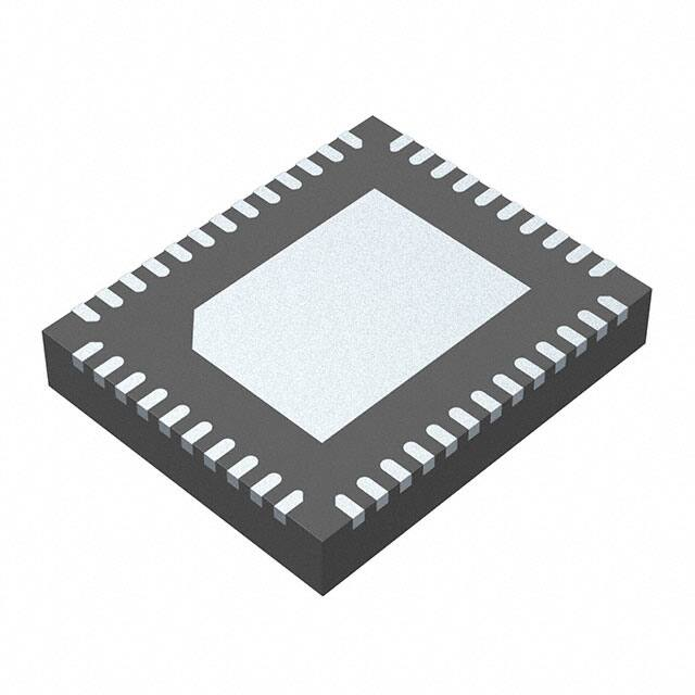
VQFN (46)
LP5036
6.00 mm × 5.00 mm
(1) For all available packages, see the orderable addendum at
the end of the data sheet.
Simplified Schematic
VVCC
VMCU
CVCC
VLED
VCC
OUT0
EN
OUT1
SDA
SCL
OUT2
ADDR0
MCU
ADDR1
LP5036
OUT33
VCAP
CVCAP
OUT34
IREF
RIREF
GND
OUT35
1
An IMPORTANT NOTICE at the end of this data sheet addresses availability, warranty, changes, use in safety-critical applications,
intellectual property matters and other important disclaimers. PRODUCTION DATA.
�LP5030, LP5036
SLVSEH1B – SEPTEMBER 2018 – REVISED JANUARY 2019
www.ti.com
Table of Contents
1
2
3
4
5
6
7
Features ..................................................................
Applications ...........................................................
Description .............................................................
Revision History.....................................................
Description (continued).........................................
Pin Configuration and Functions .........................
Specifications.........................................................
7.1
7.2
7.3
7.4
7.5
7.6
7.7
8
1
1
1
2
3
4
7
Absolute Maximum Ratings ...................................... 7
ESD Ratings.............................................................. 7
Recommended Operating Conditions....................... 7
Thermal Information .................................................. 7
Electrical Characteristics........................................... 8
Timing Requirements ................................................ 9
Typical Characteristics ............................................ 10
Detailed Description ............................................ 12
8.1 Overview ................................................................. 12
8.2 Functional Block Diagram ....................................... 12
8.3 Feature Description................................................. 12
8.4 Device Functional Modes........................................ 19
8.5 Programming .......................................................... 20
8.6 Register Maps ........................................................ 24
9
Application and Implementation ........................ 49
9.1 Application Information............................................ 49
9.2 Typical Application ................................................. 49
10 Power Supply Recommendations ..................... 51
11 Layout................................................................... 51
11.1 Layout Guidelines ................................................. 51
11.2 Layout Examples................................................... 52
12 Device and Documentation Support ................. 54
12.1
12.2
12.3
12.4
12.5
12.6
Related Links ........................................................
Receiving Notification of Documentation Updates
Community Resources..........................................
Trademarks ...........................................................
Electrostatic Discharge Caution ............................
Glossary ................................................................
54
54
54
54
54
54
13 Mechanical, Packaging, and Orderable
Information ........................................................... 54
4 Revision History
NOTE: Page numbers for previous revisions may differ from page numbers in the current version.
Changes from Revision A (December 2018) to Revision B
Page
•
Changed max standy current from 10uA to 12uA .................................................................................................................. 8
•
Changed power-save mode current from 10uA to 12uA ........................................................................................................ 8
•
Changed from LED3 to LED11............................................................................................................................................. 28
Changes from Original (September 2018) to Revision A
•
2
Page
First release of production-data data sheet ........................................................................................................................... 1
Submit Documentation Feedback
Copyright © 2018–2019, Texas Instruments Incorporated
Product Folder Links: LP5030 LP5036
�LP5030, LP5036
www.ti.com
SLVSEH1B – SEPTEMBER 2018 – REVISED JANUARY 2019
5 Description (continued)
The LP503x device controls each LED output with a 12-bit PWM resolution at 29-kHz switching frequency. This
control helps get an intensity that decreases smoothly and stops audible noise. Having different color-mixing and
intensity-control registers makes writing the software code straightforward. When targeting fade-in, fade-out type
breathing effects, the global R, G, B bank control reduces the microcontroller loading significantly. The LP503x
device also implements a PWM phase-shifting function to help reduce the input power budget when LEDs turn
on simultaneously.
The LP503x device has an automatic power-saving mode to get the ultra-low quiescent current. When channels
are all off for 30 ms, the device total power consumption is down to 10 µA, making the LP503x device a possible
alternative for battery-powered end equipment.
Submit Documentation Feedback
Copyright © 2018–2019, Texas Instruments Incorporated
Product Folder Links: LP5030 LP5036
3
�LP5030, LP5036
SLVSEH1B – SEPTEMBER 2018 – REVISED JANUARY 2019
www.ti.com
6 Pin Configuration and Functions
4
GND
VCAP
IREF
EN
SCL
SDA
VCC
ADDR1
ADDR0
GND
46
45
44
43
42
41
40
39
38
37
LP5030 RJV Package
46-Pin VQFN With Exposed Thermal Pad
Top View
Thermal
30
OUT29
OUT7
8
Pad
29
OUT28
OUT8
9
28
OUT27
OUT9
10
27
OUT26
OUT10
11
26
OUT25
OUT11
12
25
OUT24
OUT12
13
24
OUT23
23
7
22
OUT6
OUT22
NC
OUT21
NC
31
21
32
6
OUT20
5
OUT5
20
OUT4
OUT19
NC
19
33
18
4
OUT18
OUT3
OUT17
NC
17
34
OUT16
3
16
OUT2
OUT15
NC
15
NC
35
14
36
2
OUT14
1
OUT1
OUT13
OUT0
Submit Documentation Feedback
Not to scale
Copyright © 2018–2019, Texas Instruments Incorporated
Product Folder Links: LP5030 LP5036
�LP5030, LP5036
www.ti.com
SLVSEH1B – SEPTEMBER 2018 – REVISED JANUARY 2019
GND
VCAP
IREF
EN
SCL
SDA
VCC
ADDR1
ADDR0
GND
46
45
44
43
42
41
40
39
38
37
LP5036 RJV Package
46-Pin VQFN With Exposed Thermal Pad
Top View
Thermal
30
OUT29
OUT7
8
Pad
29
OUT28
OUT8
9
28
OUT27
OUT9
10
27
OUT26
OUT10
11
26
OUT25
OUT11
12
25
OUT24
OUT12
13
24
OUT23
23
7
22
OUT6
OUT22
OUT30
OUT21
OUT31
31
21
32
6
OUT20
5
OUT5
20
OUT4
OUT19
OUT32
19
33
18
4
OUT18
OUT3
OUT17
OUT33
17
34
OUT16
3
16
OUT2
OUT15
OUT34
15
OUT35
35
14
36
2
OUT14
1
OUT1
OUT13
OUT0
Not to scale
Pin Functions
PIN
NAME
NO.
I/O
DESCRIPTION
LP5030
LP5036
ADDR0
38
38
—
I2C slave-address selection pin. This pin must not be left floating.
ADDR1
39
39
—
I2C slave-address selection pin. This pin must not be left floating.
EN
43
43
I
IREF
44
44
—
Output current-reference global-setting pin
NC
31
—
—
No internal connection
NC
32
—
—
No internal connection
NC
33
—
—
No internal connection
NC
34
—
—
No internal connection
NC
35
—
—
No internal connection
NC
36
—
—
No internal connection
OUT0
1
1
O
Current sink output 0. If not used, this pin can be left floating.
OUT1
2
2
O
Current sink output 1. If not used, this pin can be left floating.
OUT2
3
3
O
Current sink output 2. If not used, this pin can be left floating.
OUT3
4
4
O
Current sink output 3. If not used, this pin can be left floating.
OUT4
5
5
O
Current sink output 4. If not used, this pin can be left floating.
OUT5
6
6
O
Current sink output 5. If not used, this pin can be left floating.
OUT6
7
7
O
Current sink output 6. If not used, this pin can be left floating.
Chip enable input pin
Submit Documentation Feedback
Copyright © 2018–2019, Texas Instruments Incorporated
Product Folder Links: LP5030 LP5036
5
�LP5030, LP5036
SLVSEH1B – SEPTEMBER 2018 – REVISED JANUARY 2019
www.ti.com
Pin Functions (continued)
PIN
NAME
NO.
I/O
DESCRIPTION
LP5030
LP5036
OUT7
8
8
O
Current sink output 7. If not used, this pin can be left floating.
OUT8
9
9
O
Current sink output 8. If not used, this pin can be left floating.
OUT9
10
10
O
Current sink output 9. If not used, this pin can be left floating.
OUT10
11
11
O
Current sink output 10. If not used, this pin can be left floating.
OUT11
12
12
O
Current sink output 11. If not used, this pin can be left floating.
OUT12
13
13
O
Current sink output 12. If not used, this pin can be left floating.
OUT13
14
14
O
Current sink output 13. If not used, this pin can be left floating.
OUT14
15
15
O
Current sink output 14. If not used, this pin can be left floating.
OUT15
16
16
O
Current sink output 15. If not used, this pin can be left floating.
OUT16
17
17
O
Current sink output 16. If not used, this pin can be left floating.
OUT17
18
18
O
Current sink output 17. If not used, this pin can be left floating.
OUT18
19
19
O
Current sink output 18. If not used, this pin can be left floating.
OUT19
20
20
O
Current sink output 19. If not used, this pin can be left floating.
OUT20
21
21
O
Current sink output 20. If not used, this pin can be left floating.
OUT21
22
22
O
Current sink output 21. If not used, this pin can be left floating.
OUT22
23
23
O
Current sink output 22. If not used, this pin can be left floating.
OUT23
24
24
O
Current sink output 23. If not used, this pin can be left floating.
OUT24
25
25
O
Current sink output 24. If not used, this pin can be left floating.
OUT25
26
26
O
Current sink output 25. If not used, this pin can be left floating.
OUT26
27
27
O
Current sink output 26. If not used, this pin can be left floating.
OUT27
28
28
O
Current sink output 27. If not used, this pin can be left floating.
OUT28
29
29
O
Current sink output 28. If not used, this pin can be left floating.
OUT29
30
30
O
Current sink output 29. If not used, this pin can be left floating.
OUT30
—
31
O
Current sink output 30. If not used, this pin can be left floating.
OUT31
—
32
O
Current sink output 31. If not used, this pin can be left floating.
OUT32
—
33
O
Current sink output 32. If not used, this pin can be left floating.
OUT33
—
34
O
Current sink output 33. If not used, this pin can be left floating.
OUT34
—
35
O
Current sink output 34. If not used, this pin can be left floating.
OUT35
—
36
O
Current sink output 35. If not used, this pin can be left floating.
SCL
42
42
I
I2C bus clock line. If not used, this pin must be connected to GND or VCC.
SDA
41
41
I/O
I2C bus data line. If not used, this pin must be connected to GND or VCC.
VCAP
45
45
—
Internal LDO output pin, this pin must be connected to a 1-µF capacitor to
GND.
VCC
40
40
I
GND
37
37
—
The ground pin for the device.
46
46
—
The ground pin for the device.
GND
GND
—
Exposed thermal pad also serves as a ground for the device.
GND
Thermal pad
6
Input power.
Submit Documentation Feedback
Copyright © 2018–2019, Texas Instruments Incorporated
Product Folder Links: LP5030 LP5036
�LP5030, LP5036
www.ti.com
SLVSEH1B – SEPTEMBER 2018 – REVISED JANUARY 2019
7 Specifications
7.1 Absolute Maximum Ratings
over operating ambient temperature range (unless otherwise noted) (1)
MIN
MAX
Voltage on EN, IREF, OUTx, SCL, SDA, VCC
–0.3
6
V
Voltage on ADDRx
–0.3
VCC+0.3
V
Voltage on VCAP
–0.3
2
V
Continuous power dissipation
UNIT
Internally limited
Junction temperature, TJ-MAX
–40
125
°C
Storage temperature, Tstg
–65
150
°C
(1)
Stresses beyond those listed under Absolute Maximum Ratings may cause permanent damage to the device. These are stress ratings
only, which do not imply functional operation of the device at these or any other conditions beyond those indicated under Recommended
Operating Conditions. Exposure to absolute-maximum-rated conditions for extended periods may affect device reliability.
7.2 ESD Ratings
VALUE
V(ESD)
(1)
(2)
Electrostatic discharge
Human-body model (HBM), per ANSI/ESDA/JEDEC JS-001 (1)
±4000
Charged-device model (CDM), per JEDEC specification JESD22-C101 (2)
±1500
UNIT
V
JEDEC document JEP155 states that 500-V HBM allows safe manufacturing with a standard ESD control process. Pins listed as ±1500
V may actually have higher performance.
JEDEC document JEP157 states that 250-V CDM allows safe manufacturing with a standard ESD control process. Pins listed as ±500 V
may actually have higher performance.
7.3 Recommended Operating Conditions
over operating ambient temperature range (unless otherwise noted)
MIN
MAX
2.7
5.5
V
Voltage on OUTx
0
5.5
V
Voltage on ADDRx, EN, SDA, SCL
0
5.5
V
Operating ambient temperature, TA
–40
85
°C
Input voltage on VCC
UNIT
7.4 Thermal Information
LP5030 or LP5036
THERMAL METRIC (1)
RJV (QFN)
UNIT
46 PINS
RθJA
Junction-to-ambient thermal resistance
35.7
°C/W
RθJC(top)
Junction-to-case (top) thermal resistance
29.1
°C/W
RθJB
Junction-to-board thermal resistance
16.2
°C/W
ψJT
Junction-to-top characterization parameter
0.9
°C/W
ψJB
Junction-to-board characterization parameter
16.2
°C/W
RθJC(bot)
Junction-to-case (bottom) thermal resistance
6.3
°C/W
(1)
For more information about traditional and new thermal metrics, see Semiconductor and ICPackage Thermal Metrics.
Submit Documentation Feedback
Copyright © 2018–2019, Texas Instruments Incorporated
Product Folder Links: LP5030 LP5036
7
�LP5030, LP5036
SLVSEH1B – SEPTEMBER 2018 – REVISED JANUARY 2019
www.ti.com
7.5 Electrical Characteristics
over operating ambient temperature range (–40°C < TA tPSM
VUVR
Undervoltage restart
VVCC rising
VUVF
Undervoltage shutdown
VVCC falling
VUV_HYS
Undervoltage shutdown hysteresis
IVCC
5.5
V
0.2
1
6
12
6.5
10
mA
6
12
µA
2.5
V
2
µA
V
0.2
V
OUTPUT STAGE (OUTx)
Maximum sink current (OUT0 – OUT35)
VVCC in full range, Max_Current_Option =
0 (bit), PWM = 100%
Maximum sink current (OUT0 – OUT35)
VVCC ≥ 3.3 V, Max_Current_Option = 1
(bit), PWM = 100%
Internal sink current limit (OUT0 –
OUT35)
VVCC in full range, Max_Current_Option =
0 (bit), VIREF = 0 V
35
55
80
Internal sink current limit (OUT0 –
OUT35)
VVCC ≥ 3.3V, Max_Current_Option=1 (bit),
VIREF = 0 V
40
75
120
Leakage current (OUT0 – OUT35)
PWM = 0%
0.1
1
IERR_DD
Device to device current error,
IERR_DD=(IAVE-ISET)/ISET×100%
VVCC = 3.3V. All channels' current set to
10 mA. PWM = 100%. Already includes
the VIREF and KIREF tolerance
–5%
5%
IERR_CC
Channel to channel current error,
IERR_CC=(IOUTX-IAVE)/IAVE×100%
VVCC = 3.3V. All channels' current set to
10 mA. PWM = 100%. Already includes
the VIREF and KIREF tolerance
–5%
5%
VIREF
IREF voltage (1)
0.7
KIREF
IREF ratio (1)
105
ƒPWM
PWM switching frequency (1)
IMAX
ILIM
ILKG
VSAT
Output saturation voltage
25.5
mA
35
mA
21
VVCC in full range, Max_Current_Option =
0 (bit), output current set to 20 mA, the
voltage when the LED current has
dropped 5%
V
29
0.25
µA
kHz
0.35
V
VVCC ≥ 3.3 V, Max_Current_Option = 1
(bit), output current set to 20 mA, the
voltage when the LED current has
dropped 5%
0.3
0.4
LOGIC INPUTS (EN, SCL, SDA, ADDRx)
VIL
Low level input voltage
VIH
High level input voltage
1.4
ILOGIC
Input current
–1
VSDA
SDA output low level
(1)
8
IPULLUP = 5 mA
0.4
V
1
µA
0.4
V
V
Specified by design
Submit Documentation Feedback
Copyright © 2018–2019, Texas Instruments Incorporated
Product Folder Links: LP5030 LP5036
�LP5030, LP5036
www.ti.com
SLVSEH1B – SEPTEMBER 2018 – REVISED JANUARY 2019
Electrical Characteristics (continued)
over operating ambient temperature range (–40°C < TA16 million (256 × 256 × 256) color-mixing.
8.3.1.2 Independent Intensity Control Per RGB LED Module
When color is fixed, the independent intensity-control is used to achieve accurate and flexible dimming control for
every RGB LED module.
8.3.1.2.1 Intensity-Control Register Configuration
Every three consecutive output channels are assigned to their respective intensity-control register
(LEDx_BRIGHTNESS). For example, OUT0, OUT1, and OUT2 are assigned to LED0_BRIGHTNESS, so it is
recommended to connect the RGB LEDs in the sequence as shown in Table 1. The LP503x device allows 256step intensity control for each RGB LED module, which helps achieve a smooth dimming effect.
Keeping FFh (default value) in the LED0_BRIGHTNESS register results in 100% dimming duty cycle. With this
setting, the users can just configure the color mixing register by channel to achieve the target dimming effect in a
single-color LED application.
8.3.1.2.2 Logarithmic- or Linear-Scale Intensity Control
For human-eye-friendly visual performance, a logarithmic-scale dimming curve is usually implemented in LED
drivers. However, for RGB LEDs, if using a single register to achieve both color mixing and intensity control,
color distortion can be observed easily when using a logarithmic scale. The LP503x device, with independent
color-mixing and intensity-control registers, implements the logarithmic scale dimming control inside the intensity
control function, which solves the color distortion issue effectively. See Figure 10. Also, the LP503x device allows
users to configure the dimming scale either logarithmically or linearly through the global Log_Scale_EN register
bit. If a special dimming curve is desired, using the linear scale with software correction is the most flexible
approach. See Figure 11.
Submit Documentation Feedback
Copyright © 2018–2019, Texas Instruments Incorporated
Product Folder Links: LP5030 LP5036
13
�LP5030, LP5036
SLVSEH1B – SEPTEMBER 2018 – REVISED JANUARY 2019
www.ti.com
Feature Description (continued)
Brightness Control
8 Bits Brightness
Linear OR
Logarithmic
Log_Scale_EN
8 Bits Brightness
Linear OR
Logarithmic
Figure 10. Logarithmic or Linear Scale Intensity Control
Logarithmic Scale Dimming Curve
100 %
80 %
80 %
PWM Output Duty
PWM Output Duty
Linear Scale Dimming Curve
100 %
60 %
40 %
60 %
40 %
20 %
20 %
0%
0%
0
32
64
96
128
160
192
LEDx_BRIGHTNESS Register Input
224
255
0
32
64
96
128
160
192
LEDx_BRIGHTNESS Register Input
224
255
Figure 11. Logarithmic vs Linear Dimming Curve
8.3.1.3 12-Bit, 29-kHz PWM Generator Per Channel
8.3.1.3.1 PWM Generator
With the inputs of the color mixing and the intensity control, the final output PWM duty cycle is defined as the
product obtained by multiplying the color-mixing register value by the related intensity-control register value. The
final output PWM duty cycle has 12 bits of control accuracy, which is achieved by a 9 bits of pure PWM
resolution and 3 bits of dithering digital control. For 3-bit dithering, every eighth pulse is made 1 LSB longer to
increase the average value by 1 / 8th. The LP503x device allows the users to enable or disable the dithering
function through the PWM_Dithering_EN register. When enabled (default), the output PWM duty-cycle accuracy
is 12 bits. When disabled, the output PWM duty-cycle accuracy is 9 bits.
To eliminate the audible noise due to the PWM switching, the LP503x device sets the PWM switching frequency
at 29-kHz, above the 20-kHz human hearing range.
14
Submit Documentation Feedback
Copyright © 2018–2019, Texas Instruments Incorporated
Product Folder Links: LP5030 LP5036
�LP5030, LP5036
www.ti.com
SLVSEH1B – SEPTEMBER 2018 – REVISED JANUARY 2019
Feature Description (continued)
8.3.1.4 PWM Phase-Shifting
A PWM phase-shifting scheme allows delaying the time when each LED driver is active. When the LED drivers
are not activated simultaneously, the peak load current from the pre-stage power supply is significantly
decreased. The scheme also reduces input-current ripple and ceramic-capacitor audible ringing. LED drivers are
grouped into three different phases.
• Phase 1—the rising edge of the PWM pulse is fixed. The falling edge of the pulse is changed when the duty
cycle changes. Phase 1 is applied to LED0, LED3, …, LED[3 × (n – 1)].
• Phase 2—the middle point of the PWM pulse is fixed. The pulse spreads in both directions when the PWM
duty cycle is increased. Phase 2 is applied to LED1, LED4, …, LED[3 × (n – 1) + 1].
• Phase 3—the falling edge of the PWM pulse is fixed. The rising edge of the pulse is changed when the duty
cycle changes. Phase 3 is applied to LED2, LED5, …, LED[3 × (n – 1) + 2].
• For LP5030, n = 10. For LP5036, n = 12.
Cycle Time
LED0
Phase 1
LED3
LED[3× (n-1)]
LED1
Phase 2
LED4
LED[3× (n-1)+1]
LED2
Phase 3
LED5
LED[3× (n-1)+2]
Phase 1
Phase 2
Phase 3
Figure 12. PWM Phase-Shifting
8.3.2 LED Bank Control
For most LED-animation effects, like blinking and breathing, all the RGB LEDs have the same lighting pattern.
Instead of controlling the individual LED separately, which occupies the microcontroller resources heavily, the
LP503x device provides an easy coding approach, the LED bank control.
Submit Documentation Feedback
Copyright © 2018–2019, Texas Instruments Incorporated
Product Folder Links: LP5030 LP5036
15
�LP5030, LP5036
SLVSEH1B – SEPTEMBER 2018 – REVISED JANUARY 2019
www.ti.com
Feature Description (continued)
Each channel can be configured as either independent control or bank control through the LEDx_Bank_EN
register. When LEDx_Bank_EN = 0 (default), the LED is controlled independently by the related color-mixing and
intensity-control registers. When LEDx_Bank_EN = 1, the LP503x device drives the LED in LED bank-control
mode. The LED bank has its own independent PWM control scheme, which is the same structure as the PWM
scheme of each channel. See Each Channel PWM Control for more details. When a channel configured as LED
bank-control mode, the related color mixing and intensity control is governed by the bank control registers
(BANK_A_COLOR, BANK_B_COLOR, BANK_C_COLOR, and BANK_BRIGHTNESS) regardless of the inputs
on its own color-mixing and intensity-control registers.
Bank Color-Mixing
Bank A:
8 Bits Color
Bank B:
8 Bits Color
Bank C:
8 Bits Color
Bank Brightness-Control
Bank PWM Generators
12 Bits / 29kHz PWM
8 Bits Brightness
12 Bits / 29kHz PWM
12 Bits / 29kHz PWM
Figure 13. Bank PWM Control Scheme
Table 1. Bank Number and LED Number Assignment
16
OUT NUMBER
BANK NUMBER
OUT0
Bank A
OUT1
Bank B
OUT2
Bank C
OUT3
Bank A
OUT4
Bank B
OUT5
Bank C
OUT6
Bank A
OUT7
Bank B
OUT8
Bank C
OUT9
Bank A
OUT10
Bank B
OUT11
Bank C
OUT12
Bank A
OUT13
Bank B
OUT14
Bank C
OUT15
Bank A
OUT16
Bank B
OUT17
Bank C
OUT18
Bank A
OUT19
Bank B
OUT20
Bank C
OUT21
Bank A
OUT22
Bank B
OUT23
Bank C
OUT24
Bank A
OUT25
Bank B
OUT26
Bank C
Submit Documentation Feedback
RGB LED MODULE NUMBER
LED0
LED1
LED2
LED3
LED4
LED5
LED6
LED7
LED8
Copyright © 2018–2019, Texas Instruments Incorporated
Product Folder Links: LP5030 LP5036
�LP5030, LP5036
www.ti.com
SLVSEH1B – SEPTEMBER 2018 – REVISED JANUARY 2019
Feature Description (continued)
Table 1. Bank Number and LED Number Assignment (continued)
(1)
OUT NUMBER
BANK NUMBER
OUT27
Bank A
OUT28
Bank B
OUT29
Bank C
OUT30
Bank A
OUT31
Bank B
OUT32
Bank C
OUT33
Bank A
OUT34
Bank B
OUT35
Bank C
RGB LED MODULE NUMBER
LED9
LED10 (1)
LED11 (1)
For LP5036 only.
With the bank control configuration, the LP503x device enables users to achieve smooth and live LED effects
globally with an ultra-simple software effort. Figure 14 shows an example using LED0 as an independent RGB
indicator and others with group breathing effect.
Figure 14. Bank PWM Control Example
Submit Documentation Feedback
Copyright © 2018–2019, Texas Instruments Incorporated
Product Folder Links: LP5030 LP5036
17
�LP5030, LP5036
SLVSEH1B – SEPTEMBER 2018 – REVISED JANUARY 2019
www.ti.com
8.3.3 Current Range Setting
The maximum constant-current value of all 30 or 36 channels is set by a single external resistor, RIREF. The
value of RIREF can be calculated by Equation 1.
VIREF
RIREF =KIREF ×
ISET
where:
•
•
KIREF = 105
VIREF = 0.7 V
(1)
With the IREF pin floating, the output current is close to zero. With the IREF pin shorted to GND, the LP503x
device provides internal current-limit protection, and the output-channel maximum current is limited to ILIM.
The LP503x device supports two levels of maximum output current, IMAX.
• When VCC is in the range from 2.7 V to 5.5 V, and the Max_Current_Option (bit) = 0, IMAX= 25.5 mA.
• When VCC is in the range from 3.3 V to 5.5 V, and the Max_Current_Option (bit) = 1, IMAX= 35 mA.
8.3.4 Automatic Power-Save Mode
When all the LED outputs are inactive, the LP503x device is able to enter power-save mode automatically, thus
lowering idle-current consumption down to 12 μA (maximum). Automatic power-save mode is enabled when
register bit Power_Save_EN = 1 (default) and all the LEDs are off for a duration of >30 ms. Almost all analog
blocks are powered down in power-save mode. If any I2C command to the device occurs, the LP503x device
returns to NORMAL mode.
8.3.5 Protection Features
8.3.5.1 Thermal Shutdown
The LP503x device implements a thermal shutdown mechanism to protect the device from damage due to
overheating. When the junction temperature rises to 160°C (typical), the device switches into shutdown mode.
The LP503x device releases thermal shutdown when the junction temperature of the device is reduced to 145°C
(typical).
8.3.5.2 UVLO
The LP503x device has an internal comparator that monitors the voltage at VCC. When VCC is below VUVF, reset
is active and the LP503x device is in the INITIALIZATION state.
18
Submit Documentation Feedback
Copyright © 2018–2019, Texas Instruments Incorporated
Product Folder Links: LP5030 LP5036
�LP5030, LP5036
www.ti.com
SLVSEH1B – SEPTEMBER 2018 – REVISED JANUARY 2019
8.4 Device Functional Modes
VCC Power Up
EN = L
SHUTDOWN
From all states
EN = H
RESET = FF or UVLO = H
From all states
INITIALIZATION
STANDBY
Chip_EN = 1
Chip_EN = 0
TSD=H
I2C Command
POWER SAVE
THERMAL
SHUTDOWN
NORMAL
Power_Save_EN =1 and
All LEDs off > 30ms
TSD=L
Figure 15. Functional Modes
•
•
•
•
•
•
INITIALIZATION: The device enters into INITIALIZATION mode when EN = H. In this mode, all the registers
are reset. Entry can also be from any state, if the RESET (register) = FFh or UVLO is active.
NORMAL: The device enters the NORMAL mode when Chip_EN (register) = 1. ICC is 10 mA (typical).
POWER SAVE: The device automatically enters the POWER SAVE mode when Power_Save_EN (register) =
1 and all the LEDs are off for a duration of >30 ms. In POWER SAVE mode, analog blocks are disabled to
minimize power consumption, but the registers retain the data and keep it available via I2C. ICC is 12 µA
(maximum). In case of any I2C command to this device, it goes back to the NORMAL mode.
SHUTDOWN: The device enters into SHUTDOWN mode from all states on VCC power up or when EN = L.
ICC is < 1 µA (max).
STANDBY: The device enters the STANDBY mode when Chip_EN (register bit) = 0. In this mode, all the
OUTx are shut down, but the registers retain the data and keep it available via I2C. STANDBY is the lowpower-consumption mode, when all circuit functions are disabled. ICC is 10 µA (maximum).
THERMAL SHUTDOWN: The device automatically enters the THERMAL SHUTDOWN mode when the
junction temperature exceeds 160°C (typical). In this mode, all the OUTx outputs are shut down. If the
junction temperature decreases below 145°C (typical), the device returns to the NORMAL mode.
Submit Documentation Feedback
Copyright © 2018–2019, Texas Instruments Incorporated
Product Folder Links: LP5030 LP5036
19
�LP5030, LP5036
SLVSEH1B – SEPTEMBER 2018 – REVISED JANUARY 2019
www.ti.com
8.5 Programming
8.5.1 I2C Interface
The I2C-compatible two-wire serial interface provides access to the programmable functions and registers on the
device. This protocol uses a two-wire interface for bidirectional communications between the devices connected
to the bus. The two interface lines are the serial data line (SDA) and the serial clock line (SCL). Every device on
the bus is assigned a unique address and acts as either a master or a slave depending on whether it generates
or receives the serial clock, SCL. The SCL and SDA lines should each have a pullup resistor placed somewhere
on the line and remain HIGH even when the bus is idle.
8.5.1.1 Data Validity
The data on SDA line must be stable during the HIGH period of the clock signal (SCL). In other words, the state
of the data line can only be changed when the clock signal is LOW.
Figure 16. Data Validity
8.5.1.2 Start and Stop Conditions
START and STOP conditions classify the beginning and the end of the data transfer session. A START condition
is defined as the SDA signal transitioning from HIGH to LOW while the SCL line is HIGH. A STOP condition is
defined as the SDA transitioning from LOW to HIGH while SCL is HIGH. The bus master always generates
START and STOP conditions. The bus is considered to be busy after a START condition and free after a STOP
condition. During data transmission, the bus master can generate repeated START conditions. First START and
repeated START conditions are functionally equivalent.
Figure 17. Start and Stop Conditions
8.5.1.3 Transferring Data
Every byte put on the SDA line must be eight bits long, with the most-significant bit (MSB) being transferred first.
Each byte of data must be followed by an acknowledge bit. The acknowledge-related clock pulse is generated by
the master. The master releases the SDA line (HIGH) during the acknowledge clock pulse. The device pulls
down the SDA line during the 9th clock pulse, signifying an acknowledge. The device generates an acknowledge
after each byte has been received.
20
Submit Documentation Feedback
Copyright © 2018–2019, Texas Instruments Incorporated
Product Folder Links: LP5030 LP5036
�LP5030, LP5036
www.ti.com
SLVSEH1B – SEPTEMBER 2018 – REVISED JANUARY 2019
Programming (continued)
There is one exception to the acknowledge-after-every-byte rule. When the master is the receiver, it must
indicate to the transmitter an end of data by not acknowledging (negative acknowledge) the last byte clocked out
of the slave. This negative acknowledge still includes the acknowledge clock pulse (generated by the master),
but the SDA line is not pulled down.
After the START condition, the bus master sends a chip address. This address is seven bits long followed by an
eighth bit, which is a data direction bit (READ or WRITE). For the eighth bit, a 0 indicates a WRITE, and a 1
indicates a READ. The second byte selects the register to which the data is written. The third byte contains data
to write to the selected register.
Figure 18. Acknowledge and Not Acknowledge on I2C Bus
8.5.1.4 I2C Slave Addressing
The device slave address is defined by connecting GND or VCC to the ADDR0 and ADDR1 pins. A total of four
independent slave addresses can be realized by combinations when GND or VCC is connected to the ADDR0
and ADDR1 pins (see Table 2 and Table 3).
The device responds to a broadcast slave address regardless of the setting of the ADDR0 and ADDR1 pins.
Global writes to the broadcast address can be used for configuring all devices simultaneously. The device
supports global read using a broadcast address; however, the data read is only valid if all devices on the I2C bus
contain the same value in the addressed register.
Table 2. Slave-Address Combinations
SLAVE ADDRESS
ADDR1
ADDR0
GND
GND
011 0000
GND
VCC
011 0001
VCC
GND
011 0010
VCC
VCC
011 0011
INDEPENDENT
BROADCAST
001 1100
Table 3. Chip Address
SLAVE ADDRESS
Independent
R/W
Bit 7
Bit 6
Bit 5
Bit 4
Bit 3
Bit 2
Bit 1
Bit 0
0
1
1
0
0
ADDR1
ADDR0
1 or 0
Submit Documentation Feedback
Copyright © 2018–2019, Texas Instruments Incorporated
Product Folder Links: LP5030 LP5036
21
�LP5030, LP5036
SLVSEH1B – SEPTEMBER 2018 – REVISED JANUARY 2019
www.ti.com
Table 3. Chip Address (continued)
SLAVE ADDRESS
Broadcast
R/W
Bit 7
Bit 6
Bit 5
Bit 4
Bit 3
Bit 2
Bit 1
Bit 0
0
0
1
1
1
0
0
1 or 0
8.5.1.5 Control-Register Write Cycle
• The master device generates a start condition.
• The master device sends the slave address (7 bits) and the data direction bit (R/W = 0).
• The slave device sends an acknowledge signal if the slave address is correct.
• The master device sends the control register address (8 bits).
• The slave device sends an acknowledge signal.
• The master device sends the data byte to be written to the addressed register.
• The slave device sends an acknowledge signal.
• If the master device sends further data bytes, the control register address of the slave is incremented by 1
after the acknowledge signal. To reduce program load time, the device supports address auto incrementation.
The register address is incremented after each 8 data bits.
• The write cycle ends when the master device creates a stop condition.
Figure 19. Write Cycle
8.5.1.6 Control-Register Read Cycle
• The master device generates a start condition.
• The master device sends the slave address (7 bits) and the data direction bit (R/W = 0).
• The slave device sends an acknowledge signal if the slave address is correct.
• The master device sends the control register address (8 bits).
• The slave device sends an acknowledge signal.
• The master device generates a repeated-start condition.
• The master device sends the slave address (7 bits) and the data direction bit (R/W = 1).
• The slave device sends an acknowledge signal if the slave address is correct.
• The slave device sends the data byte from the addressed register.
• If the master device sends an acknowledge signal, the control-register address is incremented by 1. The
slave device sends the data byte from the addressed register. To reduce program load time, the device
supports address auto incrementation. The register address is incremented after each 8 data bits.
• The read cycle ends when the master device does not generate an acknowledge signal after a data byte and
generates a stop condition.
Figure 20. Read Cycle
22
Submit Documentation Feedback
Copyright © 2018–2019, Texas Instruments Incorporated
Product Folder Links: LP5030 LP5036
�LP5030, LP5036
www.ti.com
SLVSEH1B – SEPTEMBER 2018 – REVISED JANUARY 2019
8.5.1.7 Auto-Increment Feature
The auto-increment feature allows writing or reading several consecutive registers within one transmission. For
example, when an 8-bit word is sent to the device, the internal address index counter is incremented by 1, and
the next register is written. The auto-increment feature is enabled by default and can be disabled by setting the
Auto_Incr_EN bit = 0 in the DEVICE_CONFIG1 register. The auto-increment feature is applied for the full register
address from 0h to FFh.
Submit Documentation Feedback
Copyright © 2018–2019, Texas Instruments Incorporated
Product Folder Links: LP5030 LP5036
23
�LP5030, LP5036
SLVSEH1B – SEPTEMBER 2018 – REVISED JANUARY 2019
www.ti.com
8.6 Register Maps
Table 4 lists the memory-mapped registers of the device.
Table 4. Register Maps
REGISTER
NAME
ADDR
TYPE
D7
D6
DEVICE_CONFI
G0
00h
R/W
RESERVED
Chip_EN
DEVICE_CONFI
G1
01h
R/W
LED_CONFIG0
02h
R/W
LED_CONFIG1
03h
R/W
BANK_BRIGHTN
ESS
04h
R/W
Bank_Brightness
FFh
BANK_A_COLO
R
05h
R/W
Bank_A_Color
00h
BANK_B_COLO
R
06h
R/W
Bank_B_Color
00h
BANK_C_COLO
R
07h
R/W
Bank_C_Color
00h
LED0_BRIGHTN
ESS
08h
R/W
LED0_Brightness
FFh
LED1_BRIGHTN
ESS
09h
R/W
LED1_Brightness
FFh
LED2_BRIGHTN
ESS
0Ah
R/W
LED2_Brightness
FFh
LED3_BRIGHTN
ESS
0Bh
R/W
LED3_Brightness
FFh
LED4_BRIGHTN
ESS
0Ch
R/W
LED4_Brightness
FFh
LED5_BRIGHTN
ESS
0Dh
R/W
LED5_Brightness
FFh
LED6_BRIGHTN
ESS
0Eh
R/W
LED6_Brightness
FFh
LED7_BRIGHTN
ESS
0Fh
R/W
LED7_Brightness
FFh
LED8_BRIGHTN
ESS
10h
R/W
LED8_Brightness
FFh
LED9_BRIGHTN
ESS
11h
R/W
LED9_Brightness
FFh
24
D5
RESERVED
LED7_Bank_EN
LED6_Bank_EN
D4
D3
D2
D1
D0
RESERVED
DEF
AULT
00h
Log_Scale_EN
Power_Save_EN
Auto_Incr_EN
PWM_Ditherin
g_EN
Max_Current_
Option
LED_Global
Off
3Ch
LED5_Bank_EN
LED4_Bank_EN
LED3_Bank_EN
LED2_Bank_E
N
LED1_Bank_E
N
LED0_Bank_E
N
00h
LED11_Bank_E
N
LED10_Bank_
EN
LED9_Bank_E
N
LED8_Bank_E
N
00h
RESERVED
Submit Documentation Feedback
Copyright © 2018–2019, Texas Instruments Incorporated
Product Folder Links: LP5030 LP5036
�LP5030, LP5036
www.ti.com
SLVSEH1B – SEPTEMBER 2018 – REVISED JANUARY 2019
Register Maps (continued)
Table 4. Register Maps (continued)
REGISTER
NAME
ADDR
TYPE
LED10_BRIGHT
NESS
12h
R/W
LED10_Brightness
FFh
LED11_BRIGHT
NESS
13h
R/W
LED11_Brightness
FFh
OUT0_COLOR
14h
R/W
OUT0_Color
00h
OUT1_COLOR
15h
R/W
OUT1_Color
00h
OUT2_COLOR
16h
R/W
OUT2_Color
00h
OUT3_COLOR
17h
R/W
OUT3_Color
00h
OUT4_COLOR
18h
R/W
OUT4_Color
00h
OUT5_COLOR
19h
R/W
OUT5_Color
00h
OUT6_COLOR
1Ah
R/W
OUT6_Color
00h
OUT7_COLOR
1Bh
R/W
OUT7_Color
00h
OUT8_COLOR
1Ch
R/W
OUT8_Color
00h
OUT9_COLOR
1Dh
R/W
OUT9_Color
00h
OUT10_COLOR
1Eh
R/W
OUT10_Color
00h
OUT11_COLOR
1Fh
R/W
OUT11_Color
00h
OUT12_COLOR
20h
R/W
OUT12_Color
00h
OUT13_COLOR
21h
R/W
OUT13_Color
00h
OUT14_COLOR
22h
R/W
OUT14_Color
00h
OUT15_COLOR
23h
R/W
OUT15_Color
00h
OUT16_COLOR
24h
R/W
OUT16_Color
00h
OUT17_COLOR
25h
R/W
OUT17_Color
00h
OUT18_COLOR
26h
R/W
OUT18_Color
00h
OUT19_COLOR
27h
R/W
OUT19_Color
00h
OUT20_COLOR
28h
R/W
OUT20_Color
00h
OUT21_COLOR
29h
R/W
OUT21_Color
00h
OUT22_COLOR
2Ah
R/W
OUT22_Color
00h
OUT23_COLOR
2Bh
R/W
OUT23_Color
00h
OUT24_COLOR
2Ch
R/W
OUT24_Color
00h
OUT25_COLOR
2Dh
R/W
OUT25_Color
00h
OUT26_COLOR
2Eh
R/W
OUT26_Color
00h
OUT27_COLOR
2Fh
R/W
OUT27_Color
00h
D7
D6
D5
D4
D3
D2
D1
D0
Submit Documentation Feedback
Copyright © 2018–2019, Texas Instruments Incorporated
Product Folder Links: LP5030 LP5036
DEF
AULT
25
�LP5030, LP5036
SLVSEH1B – SEPTEMBER 2018 – REVISED JANUARY 2019
www.ti.com
Register Maps (continued)
Table 4. Register Maps (continued)
REGISTER
NAME
ADDR
TYPE
OUT28_COLOR
30h
R/W
OUT28_Color
00h
OUT29_COLOR
31h
R/W
OUT29_Color
00h
OUT30_COLOR
32h
R/W
OUT30_Color
00h
OUT31_COLOR
33h
R/W
OUT31_Color
00h
OUT32_COLOR
34h
R/W
OUT32_Color
00h
OUT33_COLOR
35h
R/W
OUT33_Color
00h
OUT34_COLOR
36h
R/W
OUT34_Color
00h
OUT35_COLOR
37h
R/W
OUT35_Color
00h
RESET
38h
W
Reset
00h
26
D7
D6
D5
D4
D3
Submit Documentation Feedback
D2
D1
D0
DEF
AULT
Copyright © 2018–2019, Texas Instruments Incorporated
Product Folder Links: LP5030 LP5036
�LP5030, LP5036
www.ti.com
SLVSEH1B – SEPTEMBER 2018 – REVISED JANUARY 2019
Table 5. Access Type Codes
ACCESS TYPE
CODE
DESCRIPTION
Read Type
R
R
Read
W
Write
Write Type
W
Reset or Default Value
-n
Value after reset or the default
value
8.6.1 DEVICE_CONFIG0 (Address = 0h) [reset = 0h]
DEVICE_CONFIG0 is shown in Figure 21 and described in Table 6.
Return to Table 4.
Figure 21. DEVICE_CONFIG0 Register
7
RESERVED
R/W-0h
6
Chip_EN
R/W-0h
5
4
3
2
1
0
RESERVED
R/W-0h
Table 6. DEVICE_CONFIG0 Register Field Descriptions
Bit
Field
Type
Reset
Description
7
RESERVED
R/W
0h
Reserved
6
Chip_EN
R/W
0h
0 = LP503x not enabled
RESERVED
R/W
0h
1 = LP503x enabled
5–0
Reserved
8.6.2 DEVICE_CONFIG1 (Address = 1h) [reset = 3Ch]
DEVICE_CONFIG1 is shown in Figure 22 and described in Table 7.
Return to Table 4.
Figure 22. DEVICE_CONFIG1 Register
7
RESERVED
6
5
Log_Scale_EN
R/W-0h
R/W-1h
4
Power_Save_E
N
R/W-1h
3
Auto_Incr_EN
R/W-1h
2
1
0
PWM_Dithering Max_Current_O LED_Global Off
_EN
ption
R/W-1h
R/W-0h
R/W-0h
Table 7. DEVICE_CONFIG1 Register Field Descriptions
Bit
Field
Type
Reset
Description
7–6
RESERVED
R/W
0h
Reserved
5
Log_Scale_EN
R/W
1h
0 = Linear scale dimming curve enabled
4
Power_Save_EN
R/W
1h
3
Auto_Incr_EN
R/W
1h
2
PWM_Dithering_EN
R/W
1h
1 = Logarithmic scale dimming curve enabled
0 = Automatic power-saving mode not enabled
1 = Automatic power-saving mode enabled
0 = Automatic increment mode not enabled
1 = Automatic increment mode enabled
0 = PWM dithering mode not enabled
1 = PWM dithering mode enabled
1
Max_Current_Option
R/W
0h
0 = Output maximum current IMAX = 25.5 mA.
1 = Output maximum current IMAX = 35 mA.
Submit Documentation Feedback
Copyright © 2018–2019, Texas Instruments Incorporated
Product Folder Links: LP5030 LP5036
27
�LP5030, LP5036
SLVSEH1B – SEPTEMBER 2018 – REVISED JANUARY 2019
www.ti.com
Table 7. DEVICE_CONFIG1 Register Field Descriptions (continued)
Bit
0
Field
Type
Reset
Description
LED_Global Off
R/W
0h
0 = Normal operation
1 = Shut down all LEDs
8.6.3 LED_CONFIG0 (Address = 2h) [reset = 00h]
LED_CONFIG0 is shown in Figure 23 and described in Table 8.
Return to Table 4.
Figure 23. LED_CONFIG0 Register
7
LED7_Bank_E
N
R/W-0h
6
LED6_Bank_E
N
R/W-0h
5
LED5_Bank_E
N
R/W-0h
4
LED4_Bank_E
N
R/W-0h
3
LED3_Bank_E
N
R/W-0h
2
LED2_Bank_E
N
R/W-0h
1
LED1_Bank_E
N
R/W-0h
0
LED0_Bank_E
N
R/W-0h
Table 8. LED_CONFIG0 Register Field Descriptions
Bit
Field
Type
Reset
Description
7
LED7_Bank_EN
R/W
0h
0 = LED7 independent control mode enabled
6
LED6_Bank_EN
R/W
0h
5
LED5_Bank_EN
R/W
0h
4
LED4_Bank_EN
R/W
0h
3
LED3_Bank_EN
R/W
0h
1 = LED7 bank control mode enabled
0 = LED6 independent control mode enabled
1 = LED6 bank control mode enabled
0 = LED5 independent control mode enabled
1 = LED5 bank control mode enabled
0 = LED4 independent control mode enabled
1 = LED4 bank control mode enabled
0 = LED3 Independent control mode enabled
1 = LED3 bank control mode enabled
2
LED2_Bank_EN
R/W
0h
1
LED1_Bank_EN
R/W
0h
0
LED0_Bank_EN
R/W
0h
0 = LED2 independent control mode enabled
1 = LED2 bank control mode enabled
0 = LED1 independent control mode enabled
1 = LED1 bank control mode enabled
0 = LED0 independent control mode enabled
1 = LED0 bank control mode enabled
8.6.4 LED_CONFIG1 (Address = 3h) [reset = 00h]
LED_CONFIG1 is shown in Figure 23 and described in Table 8.
Return to Table 4.
Figure 24. LED_CONFIG1 Register
7
6
5
4
3
2
LED11_Bank_E LED10_Bank_E
N
N
R/W-0h
R/W-0h
RESERVED
R/W-0h
1
LED9_Bank_E
N
R/W-0h
0
LED8_Bank_E
N
R/W-0h
Table 9. LED_CONFIG1 Register Field Descriptions
Bit
Field
Type
Reset
Description
4–7
RESERVED
R/W
0h
Reserved
LED11_Bank_EN
R/W
0h
0 = LED11 Independent control mode enabled
3
1 =LED11 bank control mode enabled
28
Submit Documentation Feedback
Copyright © 2018–2019, Texas Instruments Incorporated
Product Folder Links: LP5030 LP5036
�LP5030, LP5036
www.ti.com
SLVSEH1B – SEPTEMBER 2018 – REVISED JANUARY 2019
Table 9. LED_CONFIG1 Register Field Descriptions (continued)
Bit
Field
Type
Reset
Description
2
LED10_Bank_EN
R/W
0h
0 = LED10 independent control mode enabled
1
LED9_Bank_EN
R/W
0h
1 = LED10 bank control mode enabled
0 =LED9 independent control mode enabled
1 = LED9 bank control mode enabled
0
LED8_Bank_EN
R/W
0h
0 = LED8 independent control mode enabled
1 = LED8 bank control mode enabled
8.6.5 BANK_BRIGHTNESS (Address = 4h) [reset = FFh]
BANK_BRIGHTNESS is shown in Figure 25 and described in Table 10.
Return to Table 4.
Figure 25. BANK_BRIGHTNESS Register
7
6
5
4
3
BANK_BRIGHTNESS
R/W-FFh
2
1
0
1
0
Table 10. BANK_BRIGHTNESS Register Field Descriptions
Bit
Field
Type
7–0
BANK_BRIGHTNESS
R/W
Reset
Description
FFh
00h = 0% of full intensity
...
80h = 50% of full
...
FFh = 100 % of full intensity
8.6.6 BANK_A_COLOR (Address = 5h) [reset = 00h]
BANK_A_COLOR is shown in Figure 26 and described in Table 11.
Return to Table 4.
Figure 26. BANK_A_COLOR Register
7
6
5
4
3
BANK_A_COLOR
R/W-0h
2
Table 11. BANK_A_COLOR Register Field Descriptions
Bit
Field
Type
Reset
Description
7–0
BANK_A_COLOR
R/W
0h
00h = The color mixing percentage is 0%.
...
80h = The color mixing percentage is 50%.
...
FFh = The color mixing percentage is 100%.
8.6.7 BANK_B_COLOR (Address = 6h) [reset = 00h]
BANK_B_COLOR is shown in Figure 27 and described in Table 12.
Return to Table 4.
Submit Documentation Feedback
Copyright © 2018–2019, Texas Instruments Incorporated
Product Folder Links: LP5030 LP5036
29
�LP5030, LP5036
SLVSEH1B – SEPTEMBER 2018 – REVISED JANUARY 2019
www.ti.com
Figure 27. BANK_B_COLOR Register
7
6
5
4
3
BANK_B_COLOR
R/W-0h
2
1
0
Table 12. BANK_B_COLOR Register Field Descriptions
Bit
Field
Type
Reset
Description
7–0
BANK_B_COLOR
R/W
0h
00h = The color mixing percentage is 0%.
...
80h = The color mixing percentage is 50%.
...
FFh = The color mixing percentage is 100%.
8.6.8 BANK_C_COLOR (Address = 7h) [reset = 00h]
BANK_C_COLOR is shown in Figure 28 and described in Table 13.
Return to Table 4.
Figure 28. BANK_C_COLOR Register
7
6
5
4
3
BANK_C_COLOR
R/W-0h
2
1
0
Table 13. BANK_C_COLOR Register Field Descriptions
Bit
Field
Type
Reset
Description
7–0
BANK_C_COLOR
R/W
0h
00h = The color mixing percentage is 0%.
...
80h = The color mixing percentage is 50%.
...
FFh = The color mixing percentage is 100%.
8.6.9 LED0_BRIGHTNESS (Address = 8h) [reset = FFh]
LED0_BRIGHTNESS is shown in Figure 29 and described in Table 14.
Return to Table 4.
Figure 29. LED0_BRIGHTNESS Register
7
6
5
4
3
LED0_BRIGHTNESS
R/W-FFh
2
1
0
Table 14. LED0_BRIGHTNESS Register Field Descriptions
Bit
Field
Type
Reset
Description
7–0
LED0_BRIGHTNESS
R/W
FFh
00h = 0% of full intensity
...
80h = 50% of full intensity
...
FFh = 100 % of full intensity
30
Submit Documentation Feedback
Copyright © 2018–2019, Texas Instruments Incorporated
Product Folder Links: LP5030 LP5036
�LP5030, LP5036
www.ti.com
SLVSEH1B – SEPTEMBER 2018 – REVISED JANUARY 2019
8.6.10 LED1_BRIGHTNESS (Address = 9h) [reset = FFh]
LED1_BRIGHTNESS is shown in Figure 30 and described in Table 15.
Return to Table 4.
Figure 30. LED1_BRIGHTNESS Register
7
6
5
4
3
LED1_BRIGHTNESS
R/W-FFh
2
1
0
1
0
1
0
Table 15. LED1_BRIGHTNESS Register Field Descriptions
Bit
Field
Type
Reset
Description
7–0
LED1_BRIGHTNESS
R/W
FFh
00h = 0% of full intensity
...
80h = 50% of full intensity
...
FFh = 100 % of full intensity
8.6.11 LED2_BRIGHTNESS (Address = 0Ah) [reset = FFh]
LED2_BRIGHTNESS is shown in Figure 31 and described in Table 16.
Return to Table 4.
Figure 31. LED2_BRIGHTNESS Register
7
6
5
4
3
LED2_BRIGHTNESS
R/W-FFh
2
Table 16. LED2_BRIGHTNESS Register Field Descriptions
Bit
Field
Type
Reset
Description
7–0
LED2_BRIGHTNESS
R/W
FFh
00h = 0% of full intensity
...
80h = 50% of full intensity
...
FFh = 100 % of full intensity
8.6.12 LED3_BRIGHTNESS (Address = 0Bh) [reset = FFh]
LED3_BRIGHTNESS is shown in Figure 32 and described in Table 17.
Return to Table 4.
Figure 32. LED3_BRIGHTNESS Register
7
6
5
4
3
LED3_BRIGHTNESS
R/W-FFh
2
Submit Documentation Feedback
Copyright © 2018–2019, Texas Instruments Incorporated
Product Folder Links: LP5030 LP5036
31
�LP5030, LP5036
SLVSEH1B – SEPTEMBER 2018 – REVISED JANUARY 2019
www.ti.com
Table 17. LED3_BRIGHTNESS Register Field Descriptions
Bit
Field
Type
Reset
Description
7–0
LED3_BRIGHTNESS
R/W
FFh
00h = 0% of full intensity
...
80h = 50% of full intensity
...
FFh = 100 % of full intensity
8.6.13 LED4_BRIGHTNESS (Address = 0Ch) [reset = FFh]
LED4_BRIGHTNESS is shown in Figure 33 and described in Table 18.
Return to Table 4.
Figure 33. LED4_BRIGHTNESS Register
7
6
5
4
3
LED4_BRIGHTNESS
R/W-FFh
2
1
0
1
0
Table 18. LED4_BRIGHTNESS Register Field Descriptions
Bit
Field
Type
Reset
Description
7–0
LED4_BRIGHTNESS
R/W
FFh
00h = 0% of full intensity
...
80h = 50% of full intensity
...
FFh = 100 % of full intensity
8.6.14 LED5_BRIGHTNESS (Address = 0Dh) [reset = FFh]
LED5_BRIGHTNESS is shown in Figure 34 and described in Table 19.
Return to Table 4.
Figure 34. LED5_BRIGHTNESS Register
7
6
5
4
3
LED5_BRIGHTNESS
R/W-FFh
2
Table 19. LED5_BRIGHTNESS Register Field Descriptions
Bit
Field
Type
Reset
Description
7–0
LED5_BRIGHTNESS
R/W
FFh
00h = 0% of full intensity
...
80h = 50% of full intensity
...
FFh = 100 % of full intensity
8.6.15 LED6_BRIGHTNESS (Address = 0Eh) [reset = FFh]
LED6_BRIGHTNESS is shown in Figure 35 and described in Table 20.
Return to Table 4.
32
Submit Documentation Feedback
Copyright © 2018–2019, Texas Instruments Incorporated
Product Folder Links: LP5030 LP5036
�LP5030, LP5036
www.ti.com
SLVSEH1B – SEPTEMBER 2018 – REVISED JANUARY 2019
Figure 35. LED6_BRIGHTNESS Register
7
6
5
4
3
LED6_BRIGHTNESS
R/W-FFh
2
1
0
1
0
1
0
Table 20. LED6_BRIGHTNESS Register Field Descriptions
Bit
Field
Type
Reset
Description
7–0
LED6_BRIGHTNESS
R/W
FFh
00h = 0% of full intensity
...
80h = 50% of full intensity
...
FFh = 100 % of full intensity
8.6.16 LED7_BRIGHTNESS (Address = 0Fh) [reset = FFh]
LED7_BRIGHTNESS is shown in Figure 36 and described in Table 21.
Return to Table 4.
Figure 36. LED7_BRIGHTNESS Register
7
6
5
4
3
LED7_BRIGHTNESS
R/W-FFh
2
Table 21. LED7_BRIGHTNESS Register Field Descriptions
Bit
Field
Type
Reset
Description
7–0
LED7_BRIGHTNESS
R/W
FFh
00h = 0% of full intensity
...
80h = 50% of full intensity
...
FFh = 100 % of full intensity
8.6.17 LED8_BRIGHTNESS (Address = 10h) [reset = FFh]
LED8_BRIGHTNESS is shown in Figure 37 and described in Table 22.
Return to Table 4.
Figure 37. LED8_BRIGHTNESS Register
7
6
5
4
3
LED8_BRIGHTNESS
R/W-FFh
2
Table 22. LED8_BRIGHTNESS Register Field Descriptions
Bit
Field
Type
Reset
Description
7–0
LED8_BRIGHTNESS
R/W
FFh
00h = 0% of full intensity
...
80h = 50% of full intensity
...
FFh = 100 % of full intensity
Submit Documentation Feedback
Copyright © 2018–2019, Texas Instruments Incorporated
Product Folder Links: LP5030 LP5036
33
�LP5030, LP5036
SLVSEH1B – SEPTEMBER 2018 – REVISED JANUARY 2019
www.ti.com
8.6.18 LED9_BRIGHTNESS (Address = 11h) [reset = FFh]
LED9_BRIGHTNESS is shown in Figure 38 and described in Table 23.
Return to Table 4.
Figure 38. LED9_BRIGHTNESS Register
7
6
5
4
3
LED9_BRIGHTNESS
R/W-FFh
2
1
0
1
0
1
0
Table 23. LED9_BRIGHTNESS Register Field Descriptions
Bit
Field
Type
Reset
Description
7–0
LED9_BRIGHTNESS
R/W
FFh
00h = 0% of full intensity
...
80h = 50% of full intensity
...
FFh = 100 % of full intensity
8.6.19 LED10_BRIGHTNESS (Address = 12h) [reset = FFh]
LED10_BRIGHTNESS is shown in Figure 39 and described in Table 24.
Return to Table 4.
Figure 39. LED10_BRIGHTNESS Register
7
6
5
4
3
LED10_BRIGHTNESS
R/W-FFh
2
Table 24. LED10_BRIGHTNESS Register Field Descriptions
Bit
Field
Type
Reset
Description
7–0
LED10_BRIGHTNESS
R/W
FFh
00h = 0% of full intensity
...
80h = 50% of full intensity
...
FFh = 100 % of full intensity
8.6.20 LED11_BRIGHTNESS (Address = 13h) [reset = FFh]
LED11_BRIGHTNESS is shown in Figure 40 and described in Table 25.
Return to Table 4.
Figure 40. LED11_BRIGHTNESS Register
7
34
6
5
4
3
LED11_BRIGHTNESS
R/W-FFh
Submit Documentation Feedback
2
Copyright © 2018–2019, Texas Instruments Incorporated
Product Folder Links: LP5030 LP5036
�LP5030, LP5036
www.ti.com
SLVSEH1B – SEPTEMBER 2018 – REVISED JANUARY 2019
Table 25. LED11_BRIGHTNESS Register Field Descriptions
Bit
Field
7–0
LED11_BRIGHTNESS
Type
Reset
R/W
FFh
Description
00h = 0% of full intensity
...
80h = 50% of full intensity
...
FFh = 100 % of full intensity
8.6.21 OUT0_COLOR (Address = 14h) [reset = 00h]
OUT0_COLOR is shown in Figure 41 and described in Table 26.
Return to Table 4.
Figure 41. OUT0_COLOR Register
7
6
5
4
3
2
1
0
OUT0_COLOR
R/W-00h
Table 26. OUT0_COLOR Register Field Descriptions
Bit
Field
Type
Reset
Description
7–0
OUT0_COLOR
R/W
00h
00h = The color mixing percentage is 0%.
...
80h = The color mixing percentage is 50%.
...
FFh = The color mixing percentage is 100%.
8.6.22 OUT1_COLOR (Address = 15h) [reset = 00h]
OUT1_COLOR is shown in Figure 42 and described in Table 27.
Return to Table 4.
Figure 42. OUT1_COLOR Register
7
6
5
4
3
2
1
0
OUT1_COLOR
R/W-00h
Table 27. OUT1_COLOR Register Field Descriptions
Bit
Field
Type
Reset
Description
7–0
OUT1_COLOR
R/W
00h
00h = The color mixing percentage is 0%.
...
80h = The color mixing percentage is 50%.
...
FFh = The color mixing percentage is 100%.
8.6.23 OUT2_COLOR (Address = 16h) [reset = 00h]
OUT2_COLOR is shown in Figure 43 and described in Table 28.
Return to Table 4.
Submit Documentation Feedback
Copyright © 2018–2019, Texas Instruments Incorporated
Product Folder Links: LP5030 LP5036
35
�LP5030, LP5036
SLVSEH1B – SEPTEMBER 2018 – REVISED JANUARY 2019
www.ti.com
Figure 43. OUT2_COLOR Register
7
6
5
4
3
2
1
0
OUT2_COLOR
R/W-00h
Table 28. OUT2_COLOR Register Field Descriptions
Bit
Field
Type
Reset
Description
7–0
OUT2_COLOR
R/W
00h
00h = The color mixing percentage is 0%.
...
80h = The color mixing percentage is 50%.
...
FFh = The color mixing percentage is 100%.
8.6.24 OUT3_COLOR (Address = 17h) [reset = 00h]
OUT3_COLOR is shown in Figure 44 and described in Table 29.
Return to Table 4.
Figure 44. OUT3_COLOR Register
7
6
5
4
3
2
1
0
OUT3_COLOR
R/W-00h
Table 29. OUT3_COLOR Register Field Descriptions
Bit
Field
Type
Reset
Description
7–0
OUT3_COLOR
R/W
00h
00h = The color mixing percentage is 0%.
...
80h = The color mixing percentage is 50%.
...
FFh = The color mixing percentage is 100%.
8.6.25 OUT4_COLOR (Address = 18h) [reset = 00h]
OUT4_COLOR is shown in Figure 45 and described in Table 30.
Return to Table 4.
Figure 45. OUT4_COLOR Register
7
6
5
4
3
2
1
0
OUT1_COLOR
R/W-00h
Table 30. OUT4_COLOR Register Field Descriptions
Bit
Field
Type
Reset
Description
7–0
OUT4_COLOR
R/W
00h
00h = The color mixing percentage is 0%.
...
80h = The color mixing percentage is 50%.
...
FFh = The color mixing percentage is 100%.
36
Submit Documentation Feedback
Copyright © 2018–2019, Texas Instruments Incorporated
Product Folder Links: LP5030 LP5036
�LP5030, LP5036
www.ti.com
SLVSEH1B – SEPTEMBER 2018 – REVISED JANUARY 2019
8.6.26 OUT5_COLOR (Address = 19h) [reset = 00h]
OUT5_COLOR is shown in Figure 46 and described in Table 31.
Return to Table 4.
Figure 46. OUT5_COLOR Register
7
6
5
4
3
2
1
0
OUT5_COLOR
R/W-00h
Table 31. OUT5_COLOR Register Field Descriptions
Bit
Field
Type
Reset
Description
7–0
OUT5_COLOR
R/W
00h
00h = The color mixing percentage is 0%.
...
80h = The color mixing percentage is 50%.
...
FFh = The color mixing percentage is 100%.
8.6.27 OUT6_COLOR (Address = 1Ah) [reset = 00h]
OUT6_COLOR is shown in Figure 47 and described in Table 32.
Return to Table 4.
Figure 47. OUT6_COLOR Register
7
6
5
4
3
2
1
0
OUT6_COLOR
R/W-00h
Table 32. OUT6_COLOR Register Field Descriptions
Bit
Field
Type
Reset
Description
7–0
OUT6_COLOR
R/W
00h
00h = The color mixing percentage is 0%.
...
80h = The color mixing percentage is 50%.
...
FFh = The color mixing percentage is 100%.
8.6.28 OUT7_COLOR (Address = 1Bh) [reset = 00h]
OUT7_COLOR is shown in Figure 48 and described in Table 33.
Return to Table 4.
Figure 48. OUT7_COLOR Register
7
6
5
4
3
2
1
0
OUT7_COLOR
R/W-00h
Submit Documentation Feedback
Copyright © 2018–2019, Texas Instruments Incorporated
Product Folder Links: LP5030 LP5036
37
�LP5030, LP5036
SLVSEH1B – SEPTEMBER 2018 – REVISED JANUARY 2019
www.ti.com
Table 33. OUT7_COLOR Register Field Descriptions
Bit
Field
Type
Reset
Description
7–0
OUT7_COLOR
R/W
00h
00h = The color mixing percentage is 0%.
...
80h = The color mixing percentage is 50%.
...
FFh = The color mixing percentage is 100%.
8.6.29 OUT8_COLOR (Address = 1Ch) [reset = 00h]
OUT8_COLOR is shown in Figure 49 and described in Table 34.
Return to Table 4.
Figure 49. OUT8_COLOR Register
7
6
5
4
3
2
1
0
OUT8_COLOR
R/W-00h
Table 34. OUT8_COLOR Register Field Descriptions
Bit
Field
Type
Reset
Description
7–0
OUT8_COLOR
R/W
00h
00h = The color mixing percentage is 0%.
...
80h = The color mixing percentage is 50%.
...
FFh = The color mixing percentage is 100%.
8.6.30 OUT9_COLOR (Address = 1Dh) [reset = 00h]
OUT9_COLOR is shown in Figure 50 and described in Table 35.
Return to Table 4.
Figure 50. OUT9_COLOR Register
7
6
5
4
3
2
1
0
OUT9_COLOR
R/W-00h
Table 35. OUT9_COLOR Register Field Descriptions
Bit
Field
Type
Reset
Description
7–0
OUT9_COLOR
R/W
00h
00h = The color mixing percentage is 0%.
...
80h = The color mixing percentage is 50%.
...
FFh = The color mixing percentage is 100%.
8.6.31 OUT10_COLOR (Address = 1Eh) [reset = 00h]
OUT10_COLOR is shown in Figure 51 and described in Table 36.
Return to Table 4.
38
Submit Documentation Feedback
Copyright © 2018–2019, Texas Instruments Incorporated
Product Folder Links: LP5030 LP5036
�LP5030, LP5036
www.ti.com
SLVSEH1B – SEPTEMBER 2018 – REVISED JANUARY 2019
Figure 51. OUT10_COLOR Register
7
6
5
4
3
OUT10_COLOR
R/W0-0h
2
1
0
Table 36. OUT10_COLOR Register Field Descriptions
Bit
Field
Type
Reset
Description
7–0
OUT10_COLOR
R/W
00h
00h = The color mixing percentage is 0%.
...
80h = The color mixing percentage is 50%.
...
FFh = The color mixing percentage is 100%.
8.6.32 OUT11_COLOR (Address = 1Fh) [reset = 00h]
OUT11_COLOR is shown in Figure 52 and described in Table 37.
Return to Table 4.
Figure 52. OUT11_COLOR Register
7
6
5
4
3
OUT11_COLOR
R/W-00h
2
1
0
Table 37. OUT11_COLOR Register Field Descriptions
Bit
Field
Type
Reset
Description
7–0
OUT11_COLOR
R/W
00h
00h = The color mixing percentage is 0%.
...
80h = The color mixing percentage is 50%.
...
FFh = The color mixing percentage is 100%.
8.6.33 OUT12_COLOR (Address = 20h) [reset = 00h]
OUT12_COLOR is shown in Figure 53 and described in Table 38.
Return to Table 4.
Figure 53. OUT12_COLOR Register
7
6
5
4
3
OUT12_COLOR
R/W-00h
2
1
0
Table 38. OUT12_COLOR Register Field Descriptions
Bit
Field
Type
Reset
Description
7–0
OUT12_COLOR
R/W
00h
00h = The color mixing percentage is 0%.
...
80h = The color mixing percentage is 50%.
...
FFh = The color mixing percentage is 100%.
Submit Documentation Feedback
Copyright © 2018–2019, Texas Instruments Incorporated
Product Folder Links: LP5030 LP5036
39
�LP5030, LP5036
SLVSEH1B – SEPTEMBER 2018 – REVISED JANUARY 2019
www.ti.com
8.6.34 OUT13_COLOR (Address = 21h) [reset = 00h]
OUT13_COLOR is shown in Figure 54 and described in Table 39.
Return to Table 4.
Figure 54. OUT13_COLOR Register
7
6
5
4
3
OUT13_COLOR
R/W-00h
2
1
0
Table 39. OUT13_COLOR Register Field Descriptions
Bit
Field
Type
Reset
Description
7–0
OUT13_COLOR
R/W
00h
00h = The color mixing percentage is 0%.
...
80h = The color mixing percentage is 50%.
...
FFh = The color mixing percentage is 100%.
8.6.35 OUT14_COLOR (Address = 22h) [reset = 00h]
OUT14_COLOR is shown in Figure 55 and described in Table 40.
Return to Table 4.
Figure 55. OUT14_COLOR Register
7
6
5
4
3
OUT14_COLOR
R/W-00h
2
1
0
Table 40. OUT14_COLOR Register Field Descriptions
Bit
Field
Type
Reset
Description
7–0
OUT14_COLOR
R/W
00h
00h = The color mixing percentage is 0%.
...
80h = The color mixing percentage is 50%.
...
FFh = The color mixing percentage is 100%.
8.6.36 OUT15_COLOR (Address = 23h) [reset = 00h]
OUT15_COLOR is shown in Figure 56 and described in Table 41.
Return to Table 4.
Figure 56. OUT15_COLOR Register
7
40
6
5
4
3
OUT15_COLOR
R/W-00h
Submit Documentation Feedback
2
1
0
Copyright © 2018–2019, Texas Instruments Incorporated
Product Folder Links: LP5030 LP5036
�LP5030, LP5036
www.ti.com
SLVSEH1B – SEPTEMBER 2018 – REVISED JANUARY 2019
Table 41. OUT15_COLOR Register Field Descriptions
Bit
Field
Type
Reset
Description
7–0
OUT15_COLOR
R/W
00h
00h = The color mixing percentage is 0%.
...
80h = The color mixing percentage is 50%.
...
FFh = The color mixing percentage is 100%.
8.6.37 OUT16_COLOR (Address = 24h) [reset = 00h]
OUT16_COLOR is shown in Figure 57 and described in Table 42.
Return to Table 4.
Figure 57. OUT16_COLOR Register
7
6
5
4
3
OUT16_COLOR
R/W-00h
2
1
0
Table 42. OUT16_COLOR Register Field Descriptions
Bit
Field
Type
Reset
Description
7–0
OUT16_COLOR
R/W
00h
00h = The color mixing percentage is 0%.
...
80h = The color mixing percentage is 50%.
...
FFh = The color mixing percentage is 100%.
8.6.38 OUT17_COLOR (Address = 25h) [reset = 00h]
OUT17_COLOR is shown in Figure 58 and described in Table 43.
Return to Table 4.
Figure 58. OUT17_COLOR Register
7
6
5
4
3
OUT17_COLOR
R/W-00h
2
1
0
Table 43. OUT17_COLOR Register Field Descriptions
Bit
Field
Type
Reset
Description
7–0
OUT17_COLOR
R/W
00h
00h = The color mixing percentage is 0%.
...
80h = The color mixing percentage is 50%.
...
FFh = The color mixing percentage is 100%.
8.6.39 OUT18_COLOR (Address = 26h) [reset = 00h]
OUT18_COLOR is shown in Figure 59 and described in Table 44.
Return to Table 4.
Submit Documentation Feedback
Copyright © 2018–2019, Texas Instruments Incorporated
Product Folder Links: LP5030 LP5036
41
�LP5030, LP5036
SLVSEH1B – SEPTEMBER 2018 – REVISED JANUARY 2019
www.ti.com
Figure 59. OUT18_COLOR Register
7
6
5
4
3
OUT18_COLOR
R/W-00h
2
1
0
Table 44. OUT18_COLOR Register Field Descriptions
Bit
Field
Type
Reset
Description
7–0
OUT18_COLOR
R/W
00h
00h = The color mixing percentage is 0%.
...
80h = The color mixing percentage is 50%.
...
FFh = The color mixing percentage is 100%.
8.6.40 OUT19_COLOR (Address = 27h) [reset = 00h]
OUT19_COLOR is shown in Figure 60 and described in Table 45.
Return to Table 4.
Figure 60. OUT19_COLOR Register
7
6
5
4
3
OUT19_COLOR
R/W-00h
2
1
0
Table 45. OUT19_COLOR Register Field Descriptions
Bit
Field
Type
Reset
Description
7–0
OUT19_COLOR
R/W
00h
00h = The color mixing percentage is 0%.
...
80h = The color mixing percentage is 50%.
...
FFh = The color mixing percentage is 100%.
8.6.41 OUT20_COLOR (Address = 28h) [reset = 00h]
OUT20_COLOR is shown in Figure 61 and described in Table 46.
Return to Table 4.
Figure 61. OUT20_COLOR Register
7
6
5
4
3
OUT20_COLOR
R/W-00h
2
1
0
Table 46. OUT20_COLOR Register Field Descriptions
Bit
Field
Type
Reset
Description
7–0
OUT20_COLOR
R/W
00h
00h = The color mixing percentage is 0%.
...
80h = The color mixing percentage is 50%.
...
FFh = The color mixing percentage is 100%.
42
Submit Documentation Feedback
Copyright © 2018–2019, Texas Instruments Incorporated
Product Folder Links: LP5030 LP5036
�LP5030, LP5036
www.ti.com
SLVSEH1B – SEPTEMBER 2018 – REVISED JANUARY 2019
8.6.42 OUT21_COLOR (Address = 29h) [reset = 00h]
OUT21_COLOR is shown in Figure 62 and described in Table 47.
Return to Table 4.
Figure 62. OUT21_COLOR Register
7
6
5
4
3
OUT21_COLOR
R/W-00h
2
1
0
Table 47. OUT21_COLOR Register Field Descriptions
Bit
Field
Type
Reset
Description
7–0
OUT21_COLOR
R/W
00h
00h = The color mixing percentage is 0%.
...
80h = The color mixing percentage is 50%.
...
FFh = The color mixing percentage is 100%.
8.6.43 OUT22_COLOR (Address = 2Ah) [reset = 00h]
OUT22_COLOR is shown in Figure 63 and described in Table 48.
Return to Table 4.
Figure 63. OUT22_COLOR Register
7
6
5
4
3
OUT22_COLOR
R/W-00h
2
1
0
Table 48. OUT22_COLOR Register Field Descriptions
Bit
Field
Type
Reset
Description
7–0
OUT22_COLOR
R/W
00h
00h = The color mixing percentage is 0%.
...
80h = The color mixing percentage is 50%.
...
FFh = The color mixing percentage is 100%.
8.6.44 OUT23_COLOR (Address = 2Bh) [reset = 00h]
OUT23_COLOR is shown in Figure 64 and described in Table 49.
Return to Table 4.
Figure 64. OUT23_COLOR Register
7
6
5
4
3
OUT23_COLOR
R/W-00h
2
1
0
Submit Documentation Feedback
Copyright © 2018–2019, Texas Instruments Incorporated
Product Folder Links: LP5030 LP5036
43
�LP5030, LP5036
SLVSEH1B – SEPTEMBER 2018 – REVISED JANUARY 2019
www.ti.com
Table 49. OUT23_COLOR Register Field Descriptions
Bit
Field
Type
Reset
Description
7–0
OUT23_COLOR
R/W
00h
00h = The color mixing percentage is 0%.
...
80h = The color mixing percentage is 50%.
...
FFh = The color mixing percentage is 100%.
8.6.45 OUT24_COLOR (Address = 2Ch) [reset = 00h]
OUT24_COLOR is shown in Figure 65 and described in Table 50.
Return to Table 4.
Figure 65. OUT24_COLOR Register
7
6
5
4
3
OUT24_COLOR
R/W-00h
2
1
0
Table 50. OUT24_COLOR Register Field Descriptions
Bit
Field
Type
Reset
Description
7–0
OUT24_COLOR
R/W
00h
00h = The color mixing percentage is 0%.
...
80h = The color mixing percentage is 50%.
...
FFh = The color mixing percentage is 100%.
8.6.46 OUT25_COLOR (Address = 2Dh) [reset = 00h]
OUT25_COLOR is shown in Figure 66 and described in Table 51.
Return to Table 4.
Figure 66. OUT25_COLOR Register
7
6
5
4
3
OUT25_COLOR
R/W-00h
2
1
0
Table 51. OUT25_COLOR Register Field Descriptions
Bit
Field
Type
Reset
Description
7–0
OUT25_COLOR
R/W
00h
00h = The color mixing percentage is 0%.
...
80h = The color mixing percentage is 50%.
...
FFh = The color mixing percentage is 100%.
8.6.47 OUT26_COLOR (Address = 2Eh) [reset = 00h]
OUT26_COLOR is shown in Figure 67 and described in Table 52.
Return to Table 4.
44
Submit Documentation Feedback
Copyright © 2018–2019, Texas Instruments Incorporated
Product Folder Links: LP5030 LP5036
�LP5030, LP5036
www.ti.com
SLVSEH1B – SEPTEMBER 2018 – REVISED JANUARY 2019
Figure 67. OUT26_COLOR Register
7
6
5
4
3
OUT26_COLOR
R/W-00h
2
1
0
Table 52. OUT26_COLOR Register Field Descriptions
Bit
Field
Type
Reset
Description
7–0
OUT26_COLOR
R/W
00h
00h = The color mixing percentage is 0%.
...
80h = The color mixing percentage is 50%.
...
FFh = The color mixing percentage is 100%.
8.6.48 OUT27_COLOR (Address = 2Fh) [reset = 00h]
OUT27_COLOR is shown in Figure 68 and described in Table 53.
Return to Table 4.
Figure 68. OUT27_COLOR Register
7
6
5
4
3
OUT27_COLOR
R/W-00h
2
1
0
Table 53. OUT27_COLOR Register Field Descriptions
Bit
Field
Type
Reset
Description
7–0
OUT27_COLOR
R/W
00h
00h = The color mixing percentage is 0%.
...
80h = The color mixing percentage is 50%.
...
FFh = The color mixing percentage is 100%.
8.6.49 OUT28_COLOR (Address = 30h) [reset = 00h]
OUT28_COLOR is shown in Figure 69 and described in Table 54.
Return to Table 4.
Figure 69. OUT28_COLOR Register
7
6
5
4
3
OUT28_COLOR
R/W-00h
2
1
0
Table 54. OUT28_COLOR Register Field Descriptions
Bit
Field
Type
Reset
Description
7–0
OUT28_COLOR
R/W
00h
00h = The color mixing percentage is 0%.
...
80h = The color mixing percentage is 50%.
...
FFh = The color mixing percentage is 100%.
Submit Documentation Feedback
Copyright © 2018–2019, Texas Instruments Incorporated
Product Folder Links: LP5030 LP5036
45
�LP5030, LP5036
SLVSEH1B – SEPTEMBER 2018 – REVISED JANUARY 2019
www.ti.com
8.6.50 OUT29_COLOR (Address = 31h) [reset = 00h]
OUT29_COLOR is shown in Figure 70 and described in Table 55.
Return to Table 4.
Figure 70. OUT29_COLOR Register
7
6
5
4
3
OUT29_COLOR
R/W-00h
2
1
0
Table 55. OUT29_COLOR Register Field Descriptions
Bit
Field
Type
Reset
Description
7–0
OUT29_COLOR
R/W
00h
00h = The color mixing percentage is 0%.
...
80h = The color mixing percentage is 50%.
...
FFh = The color mixing percentage is 100%.
8.6.51 OUT30_COLOR (Address = 32h) [reset = 00h]
OUT30_COLOR is shown in Figure 71 and described in Table 56.
Return to Table 4.
Figure 71. OUT30_COLOR Register
7
6
5
4
3
OUT30_COLOR
R/W-00h
2
1
0
Table 56. OUT30_COLOR Register Field Descriptions
Bit
Field
Type
Reset
Description
7–0
OUT30_COLOR
R/W
00h
00h = The color mixing percentage is 0%.
...
80h = The color mixing percentage is 50%.
...
FFh = The color mixing percentage is 100%.
8.6.52 OUT31_COLOR (Address = 33h) [reset = 00h]
OUT31_COLOR is shown in Figure 72 and described in Table 57.
Return to Table 4.
Figure 72. OUT31_COLOR Register
7
46
6
5
4
3
OUT31_COLOR
R/W-00h
Submit Documentation Feedback
2
1
0
Copyright © 2018–2019, Texas Instruments Incorporated
Product Folder Links: LP5030 LP5036
�LP5030, LP5036
www.ti.com
SLVSEH1B – SEPTEMBER 2018 – REVISED JANUARY 2019
Table 57. OUT31_COLOR Register Field Descriptions
Bit
Field
Type
Reset
Description
7–0
OUT31_COLOR
R/W
00h
00h = The color mixing percentage is 0%.
...
80h = The color mixing percentage is 50%.
...
FFh = The color mixing percentage is 100%.
8.6.53 OUT32_COLOR (Address = 34h) [reset = 00h]
OUT32_COLOR is shown in Figure 73 and described in Table 58.
Return to Table 4.
Figure 73. OUT32_COLOR Register
7
6
5
4
3
OUT32_COLOR
R/W-00h
2
1
0
Table 58. OUT32_COLOR Register Field Descriptions
Bit
Field
Type
Reset
Description
7–0
OUT32_COLOR
R/W
00h
00h = The color mixing percentage is 0%.
...
80h = The color mixing percentage is 50%.
...
FFh = The color mixing percentage is 100%.
8.6.54 OUT33_COLOR (Address = 35h) [reset = 00h]
OUT33_COLOR is shown in Figure 74 and described in Table 59.
Return to Table 4.
Figure 74. OUT33_COLOR Register
7
6
5
4
3
OUT33_COLOR
R/W-00h
2
1
0
Table 59. OUT33_COLOR Register Field Descriptions
Bit
Field
Type
Reset
Description
7–0
OUT33_COLOR
R/W
00h
00h = The color mixing percentage is 0%.
...
80h = The color mixing percentage is 50%.
...
FFh = The color mixing percentage is 100%.
8.6.55 OUT34_COLOR (Address = 36h) [reset = 00h]
OUT34_COLOR is shown in Figure 75 and described in Table 60.
Return to Table 4.
Submit Documentation Feedback
Copyright © 2018–2019, Texas Instruments Incorporated
Product Folder Links: LP5030 LP5036
47
�LP5030, LP5036
SLVSEH1B – SEPTEMBER 2018 – REVISED JANUARY 2019
www.ti.com
Figure 75. OUT34_COLOR Register
7
6
5
4
3
OUT34_COLOR
R/W-00h
2
1
0
Table 60. OUT34_COLOR Register Field Descriptions
Bit
Field
Type
Reset
Description
7–0
OUT34_COLOR
R/W
00h
00h = The color mixing percentage is 0%.
...
80h = The color mixing percentage is 50%.
...
FFh = The color mixing percentage is 100%.
8.6.56 OUT35_COLOR (Address = 37h) [reset = 00h]
OUT35_COLOR is shown in Figure 76 and described in Table 61.
Return to Table 4.
Figure 76. OUT35_COLOR Register
7
6
5
4
3
OUT35_COLOR
R/W-00h
2
1
0
Table 61. OUT35_COLOR Register Field Descriptions
Bit
Field
Type
Reset
Description
7–0
OUT35_COLOR
R/W
00h
00h = The color mixing percentage is 0%.
...
80h = The color mixing percentage is 50%.
...
FFh = The color mixing percentage is 100%.
8.6.57 RESET (Address = 38h) [reset = 00h]
RESET is shown in Figure 77 and described in Table 62.
Return to Table 4.
Figure 77. RESET Register
7
6
5
4
3
2
1
0
RESET
W-00h
Table 62. RESET Register Field Descriptions
48
Bit
Field
Type
Reset
Description
7–0
RESET
W
00h
FFh = Reset all the registers to default value.
Submit Documentation Feedback
Copyright © 2018–2019, Texas Instruments Incorporated
Product Folder Links: LP5030 LP5036
�LP5030, LP5036
www.ti.com
SLVSEH1B – SEPTEMBER 2018 – REVISED JANUARY 2019
9 Application and Implementation
NOTE
Information in the following applications sections is not part of the TI component
specification, and TI does not warrant its accuracy or completeness. TI’s customers are
responsible for determining suitability of components for their purposes. Customers should
validate and test their design implementation to confirm system functionality.
9.1 Application Information
The LP503x device is a 30- or 36-channel constant-current-sink LED driver. The LP503x device improves the
user experience in color mixing and intensity control, for both live effects and coding effort. The optimized
performance for RGB LEDs makes it a perfect fit for human-machine interaction applications.
9.2 Typical Application
The LP503x design supports up to four devices in parallel with different configurations on the ADDR0 and
ADDR1 pins.
VVCC
VMCU
CVCC
VLED
RPULLUP
VCC
RPULLUP
OUT0
EN
OUT1
SDA
SCL
OUT2
ADDR0
MCU
ADDR1
LP5036
OUT33
VCAP
CVCAP
OUT34
IREF
RIREF
GND
VVCC
OUT35
CVCC
VLED
VCC
OUT0
EN
OUT1
SDA
SCL
OUT2
ADDR0
ADDR1
LP5036
OUT33
VCAP
CVCAP
OUT34
IREF
RIREF
GND
OUT35
Figure 78. Driving Dual LP5036 Application Example
Submit Documentation Feedback
Copyright © 2018–2019, Texas Instruments Incorporated
Product Folder Links: LP5030 LP5036
49
�LP5030, LP5036
SLVSEH1B – SEPTEMBER 2018 – REVISED JANUARY 2019
www.ti.com
Typical Application (continued)
9.2.1 Design Requirements
Set the LED current to 15 mA using the RIREF resistor.
9.2.2 Detailed Design Procedure
The LP503x device scales up the reference current (IREF) set by the external resistor (RIREF) to sink the output
current (IOUT) at each output port. can be used to calculate the target output current IMAX_SET:
KIREF × VIREF
RIREF =
=105 ×0.7÷0.015=4900 Ÿ
I(MAX_SET)
The SCL and SDA lines must each have a pullup resistor placed somewhere on the line (the pullup resistors are
normally located on the bus master). In typical applications, values of 1.8 kΩ to 4.7 kΩ are used, depending on
the bus capacitance, I/O voltage, and the desired communication speed. Selecting a smaller value increases the
pullup speed, but slows the pulldown speed. If they want pull up quickly select the samller one but it will impact
the pull down speed.
VCAP is the internal LDO output pin. This pin must be connected through a 1-μF capacitor to GND. Put the
capacitor as close to the device as possible.
TI recommends having a 1-μF capacitor between VCC and GND to ensure proper operation. Put the capacitor as
close to the device as possible.
9.2.3 Application Curves
The test condition for is that the testing is under bank control, using the following register values: 0x02 (0xFF),
0x04 (0xF0), 0x05 (0xF0), 0x06 (0xF0). The test condition for is that the testing is under bank control, using the
following register values: 0x02 (0xFF), 0x04 (0x0F), 0x05 (0x0F), 0x06 (0x0F).
Figure 79. Current Waveform of OUT0, OUT1, OUT2 and
OUT3
50
Figure 80. Current Waveform of OUT0, OUT1, OUT2 and
OUT3
Submit Documentation Feedback
Copyright © 2018–2019, Texas Instruments Incorporated
Product Folder Links: LP5030 LP5036
�LP5030, LP5036
www.ti.com
SLVSEH1B – SEPTEMBER 2018 – REVISED JANUARY 2019
10 Power Supply Recommendations
The device is designed to operate from a VVCC input-voltage supply range between 2.7 V and 5.5 V. This input
supply must be well-regulated and able to withstand maximum input current and maintain stable voltage without
voltage drop even in a load-transition condition (start-up or rapid intensity change). The resistance of the input
supply rail must be low enough that the input-current transient does not cause a drop below the 2.7-V level in the
LP503x VVCC supply voltage.
11 Layout
11.1 Layout Guidelines
To prevent thermal shutdown, the junction temperature, TJ, must be less than T(TSD). If the voltage drop across
the output channels is high, the device power dissipation can be large. The LP503x device has very good
thermal performance because of the thermal pad design; however, the PCB layout is also very important to
ensure that the device has good thermal performance. Good PCB design can optimize heat transfer, which is
essential for the long-term reliability of the device.
Use the following guidelines when designing the device layout:
• Put the CVCAP, CVCC and RIREF as close as possible to the device. Also, TI recommends placing the ground
plane as shown in Figure 81 and Figure 82.
• Maximize the copper coverage on the PCB to increase the thermal conductivity of the board. The major heat
flow path from the package to the ambient is through copper on the PCB. Maximum copper density is
extremely important when no heat sinks are attached to the PCB on the other side from the package.
• Add as many thermal vias as possible directly under the package ground pad to maximize the thermal
conductivity of the board.
• Use either plated-shut or plugged and capped vias for all the thermal vias on both sides of the board to
prevent solder voids. To ensure reliability and performance, the solder coverage must be at least 85%.
Submit Documentation Feedback
Copyright © 2018–2019, Texas Instruments Incorporated
Product Folder Links: LP5030 LP5036
51
�LP5030, LP5036
SLVSEH1B – SEPTEMBER 2018 – REVISED JANUARY 2019
www.ti.com
GND
VCAP
IREF
EN
SCL
SDA
VCC
ADDR1
ADDR0
GND
46
45
44
43
42
41
40
39
38
37
11.2 Layout Examples
To LED
OUT0
1
36
To LED
OUT1
2
35
To LED
OUT2
3
34
To LED
OUT3
4
33
To LED
OUT4
5
32
To LED
OUT5
6
31
GND
To LED
OUT10
11
26
OUT25 To LED
To LED
OUT11
12
25
OUT24 To LED
To LED
OUT12
13
24
OUT23 To LED
23
OUT26 To LED
To LED OUT22
27
22
10
To LED OUT21
OUT9
21
To LED
To LED OUT20
OUT27 To LED
20
28
To LED OUT19
9
19
OUT8
To LED OUT18
To LED
18
OUT28 To LED
To LED OUT17
29
17
8
To LED OUT16
OUT7
16
To LED
To LED OUT15
OUT29 To LED
15
30
To LED OUT14
7
14
OUT6
To LED OUT13
To LED
GND
GND
Figure 81. LP5030 Layout Example
52
Submit Documentation Feedback
Copyright © 2018–2019, Texas Instruments Incorporated
Product Folder Links: LP5030 LP5036
�LP5030, LP5036
www.ti.com
SLVSEH1B – SEPTEMBER 2018 – REVISED JANUARY 2019
GND
VCAP
IREF
EN
SCL
SDA
VCC
ADDR1
ADDR0
GND
46
45
44
43
42
41
40
39
38
37
Layout Examples (continued)
To LED
OUT0
1
36
OUT35 To LED
To LED
OUT1
2
35
OUT34 To LED
To LED
OUT2
3
34
OUT33 To LED
To LED
OUT3
4
33
OUT32 To LED
To LED
OUT4
5
32
OUT31 To LED
To LED
OUT5
6
31
OUT30 To LED
GND
To LED
OUT10
11
26
OUT25 To LED
To LED
OUT11
12
25
OUT24 To LED
To LED
OUT12
13
24
OUT23 To LED
23
OUT26 To LED
To LED OUT22
27
22
10
To LED OUT21
OUT9
21
To LED
To LED OUT20
OUT27 To LED
20
28
To LED OUT19
9
19
OUT8
To LED OUT18
To LED
18
OUT28 To LED
To LED OUT17
29
17
8
To LED OUT16
OUT7
16
To LED
To LED OUT15
OUT29 To LED
15
30
To LED OUT14
7
14
OUT6
To LED OUT13
To LED
GND
GND
Figure 82. LP5036 Layout Example
Submit Documentation Feedback
Copyright © 2018–2019, Texas Instruments Incorporated
Product Folder Links: LP5030 LP5036
53
�LP5030, LP5036
SLVSEH1B – SEPTEMBER 2018 – REVISED JANUARY 2019
www.ti.com
12 Device and Documentation Support
12.1 Related Links
The table below lists quick access links. Categories include technical documents, support and community
resources, tools and software, and quick access to order now.
Table 63. Related Links
PARTS
PRODUCT FOLDER
ORDER NOW
TECHNICAL
DOCUMENTS
TOOLS &
SOFTWARE
SUPPORT &
COMMUNITY
LP5030
Click here
Click here
Click here
Click here
Click here
LP5036
Click here
Click here
Click here
Click here
Click here
12.2 Receiving Notification of Documentation Updates
To receive notification of documentation updates, navigate to the device product folder on ti.com. In the upper
right corner, click on Alert me to register and receive a weekly digest of any product information that has
changed. For change details, review the revision history included in any revised document.
12.3 Community Resources
The following links connect to TI community resources. Linked contents are provided "AS IS" by the respective
contributors. They do not constitute TI specifications and do not necessarily reflect TI's views; see TI's Terms of
Use.
TI E2E™ Online Community TI's Engineer-to-Engineer (E2E) Community. Created to foster collaboration
among engineers. At e2e.ti.com, you can ask questions, share knowledge, explore ideas and help
solve problems with fellow engineers.
Design Support TI's Design Support Quickly find helpful E2E forums along with design support tools and
contact information for technical support.
12.4 Trademarks
E2E is a trademark of Texas Instruments.
All other trademarks are the property of their respective owners.
12.5 Electrostatic Discharge Caution
This integrated circuit can be damaged by ESD. Texas Instruments recommends that all integrated circuits be handled with
appropriate precautions. Failure to observe proper handling and installation procedures can cause damage.
ESD damage can range from subtle performance degradation to complete device failure. Precision integrated circuits may be more
susceptible to damage because very small parametric changes could cause the device not to meet its published specifications.
12.6 Glossary
SLYZ022 — TI Glossary.
This glossary lists and explains terms, acronyms, and definitions.
13 Mechanical, Packaging, and Orderable Information
The following pages include mechanical, packaging, and orderable information. This information is the mostcurrent data available for the designated device. This data is subject to change without notice and without
revision of this document. For browser-based versions of this data sheet, see the left-hand navigation pane.
54
Submit Documentation Feedback
Copyright © 2018–2019, Texas Instruments Incorporated
Product Folder Links: LP5030 LP5036
�PACKAGE OPTION ADDENDUM
www.ti.com
10-Dec-2020
PACKAGING INFORMATION
Orderable Device
Status
(1)
Package Type Package Pins Package
Drawing
Qty
Eco Plan
(2)
Lead finish/
Ball material
MSL Peak Temp
Op Temp (°C)
Device Marking
(3)
(4/5)
(6)
LP5030RJVR
ACTIVE
VQFN
RJV
46
3000
RoHS & Green
NIPDAU
Level-2-260C-1 YEAR
-40 to 125
LP5030
LP5036RJVR
ACTIVE
VQFN
RJV
46
3000
RoHS & Green
NIPDAU
Level-2-260C-1 YEAR
-40 to 125
LP5036
(1)
The marketing status values are defined as follows:
ACTIVE: Product device recommended for new designs.
LIFEBUY: TI has announced that the device will be discontinued, and a lifetime-buy period is in effect.
NRND: Not recommended for new designs. Device is in production to support existing customers, but TI does not recommend using this part in a new design.
PREVIEW: Device has been announced but is not in production. Samples may or may not be available.
OBSOLETE: TI has discontinued the production of the device.
(2)
RoHS: TI defines "RoHS" to mean semiconductor products that are compliant with the current EU RoHS requirements for all 10 RoHS substances, including the requirement that RoHS substance
do not exceed 0.1% by weight in homogeneous materials. Where designed to be soldered at high temperatures, "RoHS" products are suitable for use in specified lead-free processes. TI may
reference these types of products as "Pb-Free".
RoHS Exempt: TI defines "RoHS Exempt" to mean products that contain lead but are compliant with EU RoHS pursuant to a specific EU RoHS exemption.
Green: TI defines "Green" to mean the content of Chlorine (Cl) and Bromine (Br) based flame retardants meet JS709B low halogen requirements of