Product
Folder
Sample &
Buy
Tools &
Software
Technical
Documents
Support &
Community
Reference
Design
LP5910
ZHCSE96A – SEPTEMBER 2015 – REVISED OCTOBER 2015
LP5910 用于 RF 和模拟电路的超低噪声、300mA 线性稳压器 - 无需旁路
电容
1 特性
•
•
•
•
•
•
•
•
1
•
•
•
•
•
3 说明
输入电压范围:1.3V 至 3.3V
输出电压范围:0.8V 至 2.3V
输出电流:300mA
电源抑制比 (PSRR):1kHz 频率时为 75dB
输出电压容差:±2%
低压降:120mV(典型值)
极低 IQ(使能时,无负载):12µA
无需噪声旁路电容即可实现超低噪声:12 µVRMS
(典型值)
与陶瓷输入和输出电容搭配使用可保持稳定
热过载保护
短路保护功能
反向电流保护
自动输出放电实现快速关断
LP5910 是一款能够提供高达 300mA 输出电流的线性
稳压器。 此器件专门针对 RF 和模拟电路而设计,可
满足其低噪声、高 PSRR、低静态电流以及出色的线
路和负载瞬态响应等诸多要求。 LP5910 采用创新的
设计技术,无需噪声旁路电容便可提供出色的噪声性
能,并且支持远距离安置输出电容。
该器件包含一个反向电流保护电路,可在输入电压低于
输出电压时防止反向电流通过 LDO 进入 IN 引脚。
当使能引脚 (EN) 为低电平且输出处于关断状态时,自
动输出放电电路会使输出电容放电以实现快速关断。
凭借低输入和低输出电压范围,LP5910 非常适合用作
后置 DC-DC 稳压器(后置降压稳压器)或者用于由单
节或两节电池供电的应用。
2 应用范围
•
•
•
•
•
•
该器件经过设计,可与一个 1μF 输入陶瓷电容和一个
1μF 输出陶瓷电容搭配使用。 无需使用独立的噪声旁
路电容。
智能电话
平板电脑
无线局域网 (LAN) 设备
针对射频 (RF)、压控振荡器 (VCO) 和锁相环 (PLL)
器件偏置的后置降压和 DC-DC 稳压
机顶盒
摄像机
其固定输出电压介于 0.8V 和 2.3V 之间(以 25mV 为
单位增量)。 如需特定的电压选项,请联系德州仪器
(TI) 销售代表。
器件信息(1)
部件号
LP5910
封装
封装尺寸(最大值)
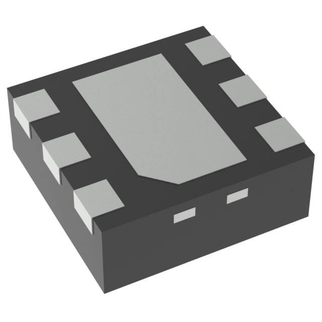
WSON (6)
2.10mm × 2.10mm
DSBGA (4)
0.742mm × 0.742mm
(1) 要了解所有可用封装,请见数据表末尾的可订购产品附录。
简化电路原理图
VIN
VOUT
IN
OUT
CIN
COUT
LP5910
Enable
EN
GND
1
An IMPORTANT NOTICE at the end of this data sheet addresses availability, warranty, changes, use in safety-critical applications,
intellectual property matters and other important disclaimers. PRODUCTION DATA.
English Data Sheet: SNVSA91
�LP5910
ZHCSE96A – SEPTEMBER 2015 – REVISED OCTOBER 2015
www.ti.com.cn
目录
1
2
3
4
5
6
7
特性 ..........................................................................
应用范围...................................................................
说明 ..........................................................................
修订历史记录 ...........................................................
Pin Configuration and Functions .........................
Specifications.........................................................
1
1
1
2
3
4
6.1
6.2
6.3
6.4
6.5
6.6
4
4
4
4
5
6
Absolute Maximum Ratings ......................................
ESD Ratings..............................................................
Recommended Operating Conditions.......................
Thermal Information ..................................................
Electrical Characteristics...........................................
Typical Characteristics ..............................................
Detailed Description ............................................ 11
7.1
7.2
7.3
7.4
Overview .................................................................
Functional Block Diagram .......................................
Feature Description.................................................
Device Functional Modes........................................
11
11
11
12
8
Applications and Implementation ...................... 13
8.1 Application Information............................................ 13
8.2 Typical Application .................................................. 13
9 Power Supply Recommendations...................... 17
10 Layout................................................................... 17
10.1
10.2
10.3
10.4
Layout Guidelines .................................................
Layout Examples...................................................
DSBGA Mounting..................................................
DSBGA Light Sensitivity .......................................
17
17
17
17
11 器件和文档支持 ..................................................... 18
11.1
11.2
11.3
11.4
11.5
文档支持................................................................
社区资源................................................................
商标 .......................................................................
静电放电警告.........................................................
Glossary ................................................................
18
18
18
18
18
12 机械、封装和可订购信息 ....................................... 18
4 修订历史记录
NOTE: Page numbers for previous revisions may differ from page numbers in the current version.
Changes from Original (September 2015) to Revision A
Page
•
已更改 器件数据表状态,从“产品预览”改为“量产数据”;在手册顶部导航栏处添加了参考设计图标 ...................................... 1
2
Copyright © 2015, Texas Instruments Incorporated
�LP5910
www.ti.com.cn
ZHCSE96A – SEPTEMBER 2015 – REVISED OCTOBER 2015
5 Pin Configuration and Functions
YKA Package
4-Pin Ultra-Thin DSBGA
Top View
IN
A1
OUT
A2
B1
EN
B2
GND
YKA Package
4-Pin Ultra-Thin DSBGA
Bottom View
OUT
IN
A1
A2
B2
GND
B1
EN
DRV Package
6-Pin WSON With Thermal Pad
Top View
OUT
1
6
IN
NC
2
5
GND
NC
3
4
EN
Pin Functions
PIN
I/O
DESCRIPTION
4
I
Enable input; disables the regulator when logic low. Enables the regulator when logic
high. An internal 1-MΩ pull down resistor connects this input to ground.
B2
5
—
A1
6
I
NC
—
2, 3
—
No internal connection. Connect to ground or leave open.
OUT
A2
1
O
Voltage output. A 1-µF low-ESR capacitor must be connected from this pin to the
GND pin. Connect this output to the load circuit.
Exposed Pad
—
Thermal Pad
—
The exposed thermal pad on the bottom of the package must be connected to a
copper area under the package on the PCB. Connect to ground potential or leave
floating. Do not connect to any potential other than the same ground potential seen at
device pin 5 (GND). See Power Dissipation for more information.
NAME
DSBGA
WSON
EN
B1
GND
IN
Copyright © 2015, Texas Instruments Incorporated
Common ground
Voltage supply input. A 1-μF capacitor must be connected at this input.
3
�LP5910
ZHCSE96A – SEPTEMBER 2015 – REVISED OCTOBER 2015
www.ti.com.cn
6 Specifications
6.1 Absolute Maximum Ratings
over operating free-air temperature range (unless otherwise noted) (1) (2)
MIN
MAX
UNIT
Input voltage, VIN
–0.3
3.6
V
Output voltage, VOUT
–0.3
3.6
V
Enable input voltage, VEN
–0.3
3.6
Continuous power dissipation (3)
Junction temperature, TJ(MAX)
Storage temperature, Tstg
(1)
(2)
(3)
V
Internally Limited
–65
W
150
°C
150
°C
Stresses beyond those listed under Absolute Maximum Ratings may cause permanent damage to the device. These are stress ratings
only, and functional operation of the device at these or any other conditions beyond those indicated under Recommended Operating
Conditions is not implied. Exposure to absolute-maximum-rated conditions for extended periods may affect device reliability.
All voltages are with respect to the GND pin.
Internal thermal shutdown circuitry protects the device from permanent damage.
6.2 ESD Ratings
VALUE
V(ESD)
(1)
(2)
Electrostatic discharge
Human-body model (HBM), per ANSI/ESDA/JEDEC JS-001 (1)
±1000
Charged-device model (CDM), per JEDEC specification JESD22-C101 (2)
±250
UNIT
V
JEDEC document JEP155 states that 500-V HBM allows safe manufacturing with a standard ESD control process.
JEDEC document JEP157 states that 250-V CDM allows safe manufacturing with a standard ESD control process.
6.3 Recommended Operating Conditions
over operating free-air temperature range (unless otherwise noted) (1)
MIN
MAX
Input voltage, VIN
1.3
3.3
UNIT
V
Output voltage, VOUT
0.8
2.3
V
Enable input voltage, VEN
0
3.3
V
Output current, IOUT
0
300
mA
Junction temperature, TJ (1)
–40
125
°C
(1)
–40
85
°C
Ambient temperature, TA
(1)
The maximum ambient temperature, (TA(MAX)) is a recommended value only and can vary depending on device power dissipation and
RθJA. For reliable operation, the junction temperature (TJ) must be limited to a maximum of 125°C. Ambient temperature (TA), thermal
resistance (RθJA) , VIN, VOUT, and IOUT all define TJ : TJ = TA + (RθJA × ((VIN – VOUT) × IOUT).
6.4 Thermal Information
LP5910
THERMAL METRIC
(1)
YKA (DSBGA)
DRV (WSON)
4 PINS
6 PINS
202.8
79.2 (3)
RθJA (2)
Junction-to-ambient thermal resistance, High-K
RθJC(top)
Junction-to-case (top) thermal resistance
3.3
110.2
RθJB
Junction-to-board thermal resistance
36.0
48.7
ψJT
Junction-to-top characterization parameter
0.4
5.2
ψJB
Junction-to-board characterization parameter
36.0
49.1
RθJC(bot)
Junction-to-case (bottom) thermal resistance
n/a
18.1
(1)
(2)
(3)
4
UNIT
°C/W
For more information about traditional and new thermal metrics, see the Semiconductor and IC Package Thermal Metrics application
report, SPRA953.
Thermal resistance value RθJA is based on the EIA/JEDEC High-K printed circuit board defined by: JESD51-7 - High Effective Thermal
Conductivity Test Board for Leaded Surface Mount Packages.
The PCB for the WSON/DRV package RθJA includes two (2) thermal vias under the exposed thermal pad per EIA/JEDEC JESD51-5.
Copyright © 2015, Texas Instruments Incorporated
�LP5910
www.ti.com.cn
ZHCSE96A – SEPTEMBER 2015 – REVISED OCTOBER 2015
6.5 Electrical Characteristics
Unless otherwise specified, VIN = VOUT(NOM) + 0.5 V, VEN = 1 V, IOUT = 1 mA, CIN = 1 µF, COUT = 1 µF. (1) (2) (3)
PARAMETER
ΔVOUT
ILOAD
TEST CONDITIONS
MIN
Output voltage tolerance
VIN = (VOUT(NOM) + 0.5 V) to 3.3 V,
IOUT = 1 mA to 300 mA
–2
Line regulation
VIN = (VOUT(NOM) + 0.5 V) to 3.3 V,
IOUT = 1 mA
Load regulation
IOUT = 1 mA to 300 mA
Load current
See (4)
230
350
VEN = 0.3 V, –40°C ≤ TJ ≤ 85°C
0.02
2
IRO
Output reverse current (6)
VOUT > VIN
VOUT = 3.3 V, VIN = VEN = 0 V
IG
Ground current (7)
IOUT = 0 mA (VOUT = 2.3 V)
PSRR
eN
TSD
Power supply rejection ratio (9)
–20
VOUT = 3.3 V, VIN = VEN = 1.3 V
0
50
µA
µA
200
300
1.5V ≤ VOUT = 2.3 V, IOUT = 300 mA
120
180
VOUT = VOUT(NOM) – 0.1 V
VIN = VOUT(NOM) + 0.5 V
450
ƒ = 1 kHz, IOUT = 20 mA, VOUT ≥ 1 V
75
ƒ = 10 kHz, IOUT = 20 mA, VOUT ≥ 1 V
65
ƒ = 100 kHz, IOUT = 20 mA, VOUT ≥ 1 V
40
ƒ = 2 MHz, IOUT = 20 mA, VOUT ≥ 1 V
25
ƒ = 100 Hz, IOUT = 20 mA, 0.8 V < VOUT < 1 V
65
ƒ = 1 kHz, IOUT = 20 mA, 0.8 V < VOUT < 1 V
65
ƒ = 10 kHz, IOUT = 20 mA, 0.8 V < VOUT < 1 V
65
ƒ = 100 kHz, IOUT = 20 mA, 0.8 V < VOUT < 1 V
40
ƒ = 2 MHz, IOUT = 20 mA, 0.8 V < VOUT < 1 V
25
Output noise voltage (9)
BW = 10 Hz to 100 kHz
Thermal shutdown
TJ rising until output is OFF
Thermal hysteresis
TJ falling from shutdown
IOUT = 1 mA
12
IOUT = 300 mA
12
µA
µA
1.3V ≤ VOUT < 1.5 V, IOUT = 300 mA
80
mA
0
15
ƒ = 100 Hz, IOUT = 20 mA, VOUT ≥ 1 V
%VOUT
%/mA
300
VEN = 1 V, IOUT = 300 mA
IQ(SD)
Output current limit
0.002
0
UNIT
%/V
25
Quiescent current in
shutdown (5)
ILIMIT
2
12
Quiescent current (5)
Dropout voltage (8)
MAX
0.01
VEN = 1 V, IOUT = 0 mA
IQ
VDO
TYP
mV
mA
dB
µVRMS
160
°C
15
LOGIC INPUT THRESHOLDS
VIL
EN low threshold (Off)
VIH
EN high threshold (On)
IEN
EN pin current (10)
VIN = 1.3 V to 3.3 V
VEN = 3.3 V, VIN = 3.3 V
VEN = 0 V, VIN = 3.3 V
0.3
V
1
3.3
0.001
µA
(1)
(2)
All voltages are with respect to the device GND pin.
Minimum and maximum limits are ensured through test, design, or statistical correlation over the TJ range of –40°C to 125°C, unless
otherwise stated. Typical values represent the most likely parametric norm at TA = 25°C, and are provided for reference purposes only.
(3) CIN, COUT: Low-ESR Surface-Mount-Ceramic Capacitors (MLCCs) used in setting electrical characteristics.
(4) The device maintains a stable, regulated output voltage without a load current.
(5) Quiescent current is defined here as the difference in current between the input voltage source and the load at VOUT. IQ = (IIN – IOUT)
(6) Output reverse current (IRO) is measured at the IN pin.
(7) Ground current is defined here as the total current flowing to ground as a result of all input voltages applied to the device.
(8) Dropout voltage is the voltage difference between the input and the output at which the output voltage drops to 100 mV below its
nominal value. Dropout voltage is not a valid condition for output voltages less than 1.3 V as compliance with the minimum operating
input voltage can not be ensured.
(9) This specification is verified by design.
(10) There is a 1-MΩ resistor between EN and ground on the device.
Copyright © 2015, Texas Instruments Incorporated
5
�LP5910
ZHCSE96A – SEPTEMBER 2015 – REVISED OCTOBER 2015
www.ti.com.cn
Electrical Characteristics (continued)
Unless otherwise specified, VIN = VOUT(NOM) + 0.5 V, VEN = 1 V, IOUT = 1 mA, CIN = 1 µF, COUT = 1 µF.(1)(2)(3)
PARAMETER
TEST CONDITIONS
TRANSIENT CHARACTERISTICS
Line transient
MIN
TYP
MAX
0
1
VIN = (VOUT(NOM) + 0.5 V) to (VOUT(NOM) + 1 V)
in 30 µs
IOUT = 1 mA
(9)
mV
VIN = (VOUT(NOM) + 1 V) to (VOUT(NOM) + 0.5 V)
in 30 µs
IOUT = 1 mA
ΔVOUT
IOUT = 1 mA to 100 mA in 10 µs
Load transient (9)
–1
0
–45
IOUT = 100 mA to 1 mA in 10 µs
mV
45
Overshoot on start-up (9)
tON
UNIT
(10)
5%
Turnon time
From VEN > VIH to VOUT = 95% of VOUT(NOM)
80
200
µs
OUTPUT DISCHARGE
Output discharge pulldown
resistance
RAD
VEN = 0 V, VIN = 2.3 V
Ω
160
6.6 Typical Characteristics
Unless otherwise stated: VOUT = 1.8 V, VIN = VOUT + 0.5 V, VEN = VIN, IOUT = 1 mA, CIN = 1 µF, COUT = 1 µF, TJ = 25°C.
1.2
1.2
ON (VIH)
OFF (VIL)
1.1
1
1
0.9
VEN Thresholds (V)
Enable Threshold (V)
ON (VIH)
OFF (VIL)
1.1
0.8
0.7
0.6
0.5
0.9
0.8
0.7
0.6
0.5
0.4
0.4
0.3
0.3
0.2
-50
0.2
-25
0
25
50
75
Junction Temperature (°C)
VIN = 2.3 V
100
125
1
2.5
3
3.5
D002
VOUT = 1.8 V
Figure 1. VEN Threshold vs Temperature
Figure 2. VEN Thresholds vs VIN
1.2
ON (VIH)
OFF (VIL)
1.1
ON (VIH)
OFF (VIL)
1.1
1
1
VEN Thresholds (V)
VEN Thresholds (V)
2
VIN (V)
1.2
0.9
0.8
0.7
0.6
0.5
0.9
0.8
0.7
0.6
0.5
0.4
0.4
0.3
0.3
0.2
0.2
1
1.5
2
2.5
3
VIN (V)
TJ = –40°C
Figure 3. VEN Thresholds vs VIN
6
1.5
D001
3.5
1
1.5
2
2.5
3
VIN (V)
D003
3.5
D004
TJ = 125°C
Figure 4. VEN Thresholds vs VIN
Copyright © 2015, Texas Instruments Incorporated
�LP5910
www.ti.com.cn
ZHCSE96A – SEPTEMBER 2015 – REVISED OCTOBER 2015
Typical Characteristics (continued)
2
2
1.8
1.8
1.6
1.6
1.4
1.4
1.2
1.2
VOUT (V)
VOUT (V)
Unless otherwise stated: VOUT = 1.8 V, VIN = VOUT + 0.5 V, VEN = VIN, IOUT = 1 mA, CIN = 1 µF, COUT = 1 µF, TJ = 25°C.
1
0.8
0.6
1
0.8
0.6
0.4
0.4
18 k: (100 µA)
1.8 k: (1 mA)
180 : (10 mA)
0.2
180 : (10 mA)
18 : (100 mA)
6 : (300 mA)
0.2
0
0
0
0.5
1
1.5
2
VIN (V)
2.5
3
3.5
0
0.5
1
D005
VEN = VIN
Figure 5. VOUT vs VIN
3
3.5
D006
Figure 6. VOUT vs VIN
25
125°C
85°C
25°C
-40°C
125°C
85°C
25°C
-40°C
20
IQ [No Load] (µA)
20
IQ [No Load] (µA)
2.5
VEN = VIN
25
15
10
5
15
10
5
0
0
0
0.5
1
VOUT = 0.8 V
1.5
2
VIN (V)
2.5
3
3.5
0
0.5
1
D007
VEN = VIN
No load
VOUT = 1.2 V
1.5
2
VIN (V)
2.5
3
3.5
D008
VEN = VIN
Figure 7. IQ vs VIN
No load
Figure 8. IQ vs VIN
25
25
125°C
85°C
25°C
-40°C
125°C
85°C
25°C
-40°C
20
IQ [No Load] (µA)
20
IQ [No Load] (µA)
1.5
2
VIN (V)
15
10
5
15
10
5
0
0
0
0.5
VOUT = 1.8 V
1
1.5
2
VIN (V)
2.5
VEN = VIN
Figure 9. IQ vs VIN
Copyright © 2015, Texas Instruments Incorporated
3
3.5
0
0.5
D009
No load
VOUT = 2.3 V
1
1.5
2
VIN (V)
2.5
VEN = VIN
3
3.5
D010
No load
Figure 10. IQ vs VIN
7
�LP5910
ZHCSE96A – SEPTEMBER 2015 – REVISED OCTOBER 2015
www.ti.com.cn
Typical Characteristics (continued)
0
0
-10
-10
-20
-20
-30
-30
PSRR (dB)
PSRR (dB)
Unless otherwise stated: VOUT = 1.8 V, VIN = VOUT + 0.5 V, VEN = VIN, IOUT = 1 mA, CIN = 1 µF, COUT = 1 µF, TJ = 25°C.
-40
-50
-60
-40
-50
-60
-70
-70
-80
-80
-90
-90
-100
10
-100
10
100
1k
VOUT = 0.8 V
10k
100k
Frequency (Hz)
1M
10M
100
D011
VIN = 1.3 V
IOUT = 20 mA
VOUT = 1.8 V
0.5
-10
0.45
-20
0.4
-30
0.35
-40
-50
-60
-70
VOUT = 2.3 V
1M
0
10
10M
1 mA
300 mA
100
D013
VIN = 2.8 V
IOUT = 20 mA
VOUT = 0.8 V
Figure 13. PSRR vs Frequency
1000
10000
Frequency (Hz)
100000
1000000
D014
VIN = 1.3 V
Figure 14. Noise Density
0.5
1.5
1 mA
300 mA
0.45
1.25
1
0.4
0.75
0.35
0.5
0.3
'VOUT (%)
Noise (µV / —Hz)
IOUT = 20 mA
0.15
0.1
10k
100k
Frequency (Hz)
D012
VIN = 2.3 V
0.2
0.05
1k
10M
0.3
-90
100
1M
0.25
-80
-100
10
10k
100k
Frequency (Hz)
Figure 12. PSRR vs Frequency
0
Noise (µV / —Hz)
PSRR (dB)
Figure 11. PSRR vs Frequency
1k
0.25
0.2
0.25
0
-0.25
-0.5
0.15
-0.75
0.1
-1
0.05
0
10
-1.25
100
VOUT = 2.3 V
1000
10000
Frequency (Hz)
100000
VIN = 2.8 V
Figure 15. Noise Density
8
1000000
-1.5
-50
-25
D015
VIN = VOUT + 0.5 V
0
25
50
75
Junction Temperature (°C)
100
125
D016
IOUT = 1 mA
Figure 16. ΔVOUT vs Temperature
Copyright © 2015, Texas Instruments Incorporated
�LP5910
www.ti.com.cn
ZHCSE96A – SEPTEMBER 2015 – REVISED OCTOBER 2015
Typical Characteristics (continued)
Unless otherwise stated: VOUT = 1.8 V, VIN = VOUT + 0.5 V, VEN = VIN, IOUT = 1 mA, CIN = 1 µF, COUT = 1 µF, TJ = 25°C.
250
250
VIN = 3.3 V
VIN = 1.3 V
VIN = 3.3 V
VIN = 2.3 V
225
200
200
175
175
150
150
IGND (µA)
IGND (µA)
225
125
100
125
100
75
75
50
50
25
25
0
0
0
50
100
150
IOUT (mA)
200
250
0
300
50
100
D017
VOUT = 0.8 V
200
250
300
D018
VOUT = 1.8 V
Figure 17. IGND vs IOUT
Figure 18. IGND vs IOUT
250
300
VIN = 3.3 V
VIN = 2.8 V
225
VOUT = 1.2 V
VOUT = 1.8 V
VOUT = 2.3 V
250
200
175
200
150
VDO (mV)
IGND (µA)
150
IOUT (mA)
125
100
150
100
75
50
50
25
0
0
0
50
100
150
IOUT (mA)
200
250
300
0
50
100
D019
150
IOUT (mA)
200
250
300
D020
VOUT = 2.3 V
Figure 20. Dropout Voltage vs IOUT
2.5
1.5
1.5
1
1
0.5
0.5
IOUT (mA)
2
VOUT (V)
VIN (V)
2
120
12
100
8
80
4
60
0
40
-4
20
-8
IOUT
'VOUT
VIN
VOUT
0
-25
0
VEN = VIN
25
50
75
Time (µs)
100
VOUT = 1.8 V
Figure 21. Turnon Time
Copyright © 2015, Texas Instruments Incorporated
125
'VOUT (mV)
Figure 19. IGND vs IOUT
2.5
0
150
0
-20
-10
0
10
D021
COUT = 1 µF
VIN = 2.3 V
IOUT = 1 mA to 100 mA
20
30
40
Time (µs)
VOUT = 1.8 V
50
60
70
-12
80
D022
COUT = 1 µF
tRISE = 10 µs
Figure 22. Load Transient Response
9
�LP5910
ZHCSE96A – SEPTEMBER 2015 – REVISED OCTOBER 2015
www.ti.com.cn
Typical Characteristics (continued)
12
8
2.5
8
80
4
2.0
4
60
0
1.5
0
40
-4
1.0
-4
20
-8
0.5
IOUT (mA)
100
VIN (V)
3.0
IOUT
'VOUT
'VOUT (mV)
12
120
'VOUT (mV)
Unless otherwise stated: VOUT = 1.8 V, VIN = VOUT + 0.5 V, VEN = VIN, IOUT = 1 mA, CIN = 1 µF, COUT = 1 µF, TJ = 25°C.
-8
VIN (V)
'VOUT (mV)
0
-20
-10
0
10
VIN = 2.3 V
IOUT = 100 mA to 1 mA
20
30
40
Time (µs)
50
VOUT = 1.8 V
tFALL = 10 µs
60
70
0.0
0
50
100
D023
COUT = 1 µF
Figure 23. Load Transient Response
10
-12
80
ΔVIN = 0.5 V
tRISE = tFALL = 30 µs
150
200 250 300
Time (Ps)
VOUT = 1.8 V
IOUT = 1 mA
350
400
450
-12
500
D024
COUT = 1 µF
Figure 24. Line Transient Response
Copyright © 2015, Texas Instruments Incorporated
�LP5910
www.ti.com.cn
ZHCSE96A – SEPTEMBER 2015 – REVISED OCTOBER 2015
7 Detailed Description
7.1 Overview
The LP5910 is a linear regulator capable of supplying 300-mA output current. Designed to meet the requirements
of RF and analog circuits, the LP5910 device provides low noise, high PSRR, low quiescent current, and low
line/load transient response figures. Using new innovative design techniques the LP5910 offers class-leading
noise performance without a noise bypass capacitor and the option for remote output capacitor placement.
7.2 Functional Block Diagram
Current
limit
IN
OUT
VIN
EA
Bandgap
Output
discharge
EN
EN
Control
GND
7.3 Feature Description
7.3.1 No-Load Stability
The LP5910 remains stable and in regulation with no external load.
7.3.2 Thermal Overload Protection
The LP5910 contains a thermal shutdown protection circuit to turn off the output current when excessive heat is
dissipated in the LDO. Thermal shutdown occurs when the thermal junction temperature (TJ) of the main passFET exceeds 160°C (typical). Thermal shutdown hysteresis assures that the LDO again resets (turns on) when
the temperature falls to 145°C (typical).
7.3.3 Short-Circuit Protection
The LP5910 contains internal current limit which reduces output current to a safe value if the output is
overloaded or shorted. Depending upon the value of VIN, thermal limiting may also become active as the average
power dissipated causes the die temperature to increase to the limit value (about 160°C). The hysteresis of the
thermal shutdown circuitry can result in a cyclic behavior on the output as the die temperature heats and cools.
7.3.4 Output Automatic Discharge
The LP5910 output employs an internal 160-Ω (typical) pulldown resistance to discharge the output when the EN
pin is low, and the device is disabled.
Copyright © 2015, Texas Instruments Incorporated
11
�LP5910
ZHCSE96A – SEPTEMBER 2015 – REVISED OCTOBER 2015
www.ti.com.cn
Feature Description (continued)
7.3.5 Reverse Current Protection
The device contains a reverse current protection circuit that prevents a backward current flowing through the
LDO from the OUT pin to the IN pin.
7.4 Device Functional Modes
7.4.1 Enable (EN)
The LP5910 may be switched to the ON or OFF state by logic input at the EN pin. A logic-high voltage on the EN
pin turns the device to the ON state. A logic-low voltage on the EN pin turns the device to the OFF state. If the
application does not require the shutdown feature, the EN pin must be tied to VIN to keep the regulator output
permanently in the ON state when power is applied
To ensure proper operation, the signal source used to drive the EN input must be able to swing above and below
the specified turnon or turnoff voltage thresholds listed in the Electrical Characteristics section under VIL and VIH.
A 1-MΩ pulldown resistor ties the EN input to ground. If the EN pin is left open, the internal 1-MΩ pulldown
resistor ensures that the device is turned into an OFF state by default.
When the EN pin is low, and the output is in an OFF state, the output activates an internal pulldown resistance to
discharge the output capacitance for fast turnoff.
12
Copyright © 2015, Texas Instruments Incorporated
�LP5910
www.ti.com.cn
ZHCSE96A – SEPTEMBER 2015 – REVISED OCTOBER 2015
8 Applications and Implementation
NOTE
Information in the following applications sections is not part of the TI component
specification, and TI does not warrant its accuracy or completeness. TI’s customers are
responsible for determining suitability of components for their purposes. Customers should
validate and test their design implementation to confirm system functionality.
8.1 Application Information
The LP5910 is designed to meet the requirements of RF and analog circuits, by providing low noise, high PSRR,
low quiescent current, and low line or load transient response figures. The device offers excellent noise
performance without the need for a noise bypass capacitor and is stable with input and output capacitors with a
value of 1 µF. The LP5910 delivers this performance in an industry-standard DSBGA package which, for this
device, is specified with a TJ of –40°C to +125°C.
8.2 Typical Application
Figure 25 shows the typical application circuit for the LP5910. Input and output capacitances may need to be
increased above 1-µF minimum for some applications.
VIN
VOUT
IN
OUT
1 µF
1 µF
LP5910
Enable
EN
GND
Figure 25. LP5910 Typical Application
8.2.1 Design Requirements
For typical LP5910 applications, use the parameters listed in Table 1.
Table 1. Design Parameters
DESIGN PARAMETER
EXAMPLE VALUE
Input voltage
1.3 V to 3.3 V
Output voltage
0.8 V to 2.3 V
Output current
300 mA
Output capacitor range
1 µF to 10 µF
8.2.2 Detailed Design Procedure
8.2.2.1 External Capacitors
Like most low-dropout regulators, the LP5910 requires external capacitors for regulator stability. The device is
specifically designed for portable applications requiring minimum board space and smallest components. These
capacitors must be correctly selected for good performance.
Copyright © 2015, Texas Instruments Incorporated
13
�LP5910
ZHCSE96A – SEPTEMBER 2015 – REVISED OCTOBER 2015
www.ti.com.cn
8.2.2.2 Input Capacitor
An input capacitor is required for stability. It is recommended that a 1-µF capacitor be connected from the
LP5910 IN pin to ground. (This capacitance value may be increased without limit.) The input capacitor must be
located a distance of not more than 1 cm from the IN pin and returned to a clean analog ground. Any good
quality ceramic, tantalum, or film capacitor may be used at the input.
NOTE
Tantalum capacitors can suffer catastrophic failures due to surge current when connected
to a low-impedance source of power (like a battery or a very large capacitor). If a tantalum
capacitor is used at the input, it must be guaranteed by the manufacturer to have a surge
current rating sufficient for the application. There are no requirements for the equivalent
series resistance (ESR) on the input capacitor, but tolerance and temperature coefficient
must be considered when selecting the capacitor to ensure the capacitance remains 1 µF
±30% over the entire operating temperature range.
8.2.2.3 Output Capacitor
For capacitance values in the range of 1 µF to 4.7 µF, ceramic capacitors are the smallest, least expensive and
have the lowest ESR values, thus making them best for eliminating high frequency noise. The ESR of a typical 1µF ceramic capacitor is in the range of 20 mΩ to 40 mΩ, which easily meets the ESR requirement for stability for
the LP5910. The temperature performance of ceramic capacitors varies by type. Most large value ceramic
capacitors ( ≥ 2.2 µF) are manufactured with Z5U or Y5V temperature characteristics, which results in the
capacitance dropping by more than 50% as the temperature goes from 25°C to 85°C.
A better choice for temperature coefficient in a ceramic capacitor is X7R. This type of capacitor is the most stable
and holds the capacitance within ±15% over the temperature range. Tantalum capacitors are less desirable than
ceramic for use as output capacitors because they are more expensive when comparing equivalent capacitance
and voltage ratings in the 1-µF to 4.7-µF range.
8.2.2.4 Capacitor Characteristics
The LP5910 is designed to work with ceramic capacitors on the input and output to take advantage of the
benefits they offer. For capacitance values in the range of 1 µF to 10 µF, ceramic capacitors are the smallest,
least expensive and have the lowest ESR values, thus making them best for eliminating high frequency noise.
The ESR of a typical 1-µF ceramic capacitor is in the range of 20 mΩ to 40 mΩ, which easily meets the ESR
requirement for stability for the LP5910.
A better choice for temperature coefficient in a ceramic capacitor is X7R. This type of capacitor is the most stable
and holds the capacitance within ±15% over the temperature range. Tantalum capacitors are less desirable than
ceramic for use as output capacitors because they are more expensive when comparing equivalent capacitance
and voltage ratings in the 1-µF to 10-µF range.
Another important consideration is that tantalum capacitors have higher ESR values than equivalent size
ceramics. This means that while it may be possible to find a tantalum capacitor with an ESR value within the
stable range, it would have to be larger in capacitance (which means bigger and more costly) than a ceramic
capacitor with the same ESR value. Also, the ESR of a typical tantalum increases about 2:1 as the temperature
goes from 25°C down to –40°C, so some guard band must be allowed.
8.2.2.5 Remote Capacitor Operation
The LP5910 requires at least a 1-µF capacitor at the OUT pin, but there is no strict requirements about the
location of the capacitor in regards to the pin. In practical designs the output capacitor may be located up to
10 cm away from the LDO. This means that there is no need to have a special capacitor close to the OUT pin if
there is already respective capacitors in the system (like a capacitor at the input of supplied part). The remote
capacitor feature helps user to minimize the number of capacitors in the system.
14
Copyright © 2015, Texas Instruments Incorporated
�LP5910
www.ti.com.cn
ZHCSE96A – SEPTEMBER 2015 – REVISED OCTOBER 2015
As a good design practice, keep the wiring parasitic inductance at a minimum, using as wide as possible traces
from the LDO output to the capacitors, keeping the LDO output trace layer as close as possible to ground layer
and avoiding vias on the path. If there is a need to use vias, implement as many vias as possible between the
connection layers. It is recommended to keep parasitic wiring inductance less than 35 nH. For the applications
with fast load transients, an input capacitor is recommended, equal to or larger to the sum of the capacitance at
the output node, for the best load-transient performance.
8.2.2.6 No-Load Stability
The LP5910 remains stable, and in regulation, with no external load.
8.2.2.7 Enable Control
The LP5910 may be switched to an ON or OFF state by a logic input at the EN pin. A voltage on this pin greater
than VIH turns the device on, while a voltage less than VIL turns the device off.
When the EN pin is low, the regulator output is off and the device typically consumes less than 1 µA.
Additionally, an output pulldown circuit is activated which ensures that any charge stored on COUT is discharged
to ground.
If the application does not require the use of the shutdown feature, the EN pin can be tied directly to the IN pin to
keep the regulator output permanently on.
An internal 1-MΩ pulldown resistor ties the EN input to ground, ensuring that the device remains off if the EN pin
is left open circuit. To ensure proper operation, the signal source used to drive the EN pin must be able to swing
above and below the specified turn-on/off voltage thresholds listed in the Electrical Characteristics under VIL and
VIH.
Table 2. Recommended Output Capacitor Specification
PARAMETER
Output capacitor, COUT
TEST CONDITIONS
Capacitance for stability
ESR
MIN
NOM
MAX
0.7
1
10
µF
500
mΩ
5
UNIT
8.2.2.8 Power Dissipation
Knowing the device power dissipation and proper sizing of the thermal plane connected to the tab or pad is
critical to ensuring reliable operation. Device power dissipation depends on input voltage, output voltage, and
load conditions and can be calculated with Equation 1.
PD(MAX) = (VIN(MAX) – VOUT) × IOUT(MAX)
(1)
Power dissipation can be minimized, and greater efficiency can be achieved, by using the lowest available
voltage drop option that would still be greater than the dropout voltage (VDO). However, keep in mind that higher
voltage drops result in better dynamic (that is, PSRR and transient) performance.
On the WSON (DRV) package, the primary conduction path for heat is through the exposed power pad to the
PCB. To ensure the device does not overheat, connect the exposed pad, through thermal vias, to an internal
ground plane with an appropriate amount of copper PCB area .
On the DSBGA (YKA) package, the primary conduction path for heat is through the four bumps to the PCB.
The maximum allowable junction temperature (TJ(MAX)) determines maximum power dissipation allowed (PD(MAX))
for the device package.
Power dissipation and junction temperature are most often related by the junction-to-ambient thermal resistance
(RθJA) of the combined PCB and device package and the temperature of the ambient air (TA), according to
Equation 2 or Equation 3:
TJ(MAX) = TA(MAX) + (RθJA × PD(MAX))
PD(MAX) = (TJ(MAX) - TA(MAX)) / RθJA
(2)
(3)
Copyright © 2015, Texas Instruments Incorporated
15
�LP5910
ZHCSE96A – SEPTEMBER 2015 – REVISED OCTOBER 2015
www.ti.com.cn
Unfortunately, this RθJA is highly dependent on the heat-spreading capability of the particular PCB design, and
therefore varies according to the total copper area, copper weight, and location of the planes. The RθJA recorded
in Thermal Information is determined by the specific EIA/JEDEC JESD51-7 standard for PCB and copperspreading area, and is to be used only as a relative measure of package thermal performance. For a welldesigned thermal layout, RθJA is actually the sum of the package junction-to-case (bottom) thermal resistance
(RθJCbot) plus the thermal resistance contribution by the PCB copper area acting as a heat sink.
8.2.2.9 Estimating Junction Temperature
The EIA/JEDEC standard recommends the use of psi (Ψ) thermal characteristics to estimate the junction
temperatures of surface mount devices on a typical PCB board application. These characteristics are not true
thermal resistance values, but rather package specific thermal characteristics that offer practical and relative
means of estimating junction temperatures. These psi metrics are determined to be significantly independent of
copper-spreading area. The key thermal characteristics (ΨJT and ΨJB) are given in Thermal Information and are
used in accordance with Equation 4 or Equation 5.
TJ(MAX) = TTOP + (ΨJT × PD(MAX))
where
•
•
PD(MAX) is explained in Equation 1.
TTOP is the temperature measured at the center-top of the device package.
(4)
TJ(MAX) = TBOARD + (ΨJB × PD(MAX))
where
•
•
PD(MAX) is explained in Equation 1.
TBOARD is the PCB surface temperature measured 1-mm from the device package and centered on the
package edge.
(5)
For more information about the thermal characteristics ΨJT and ΨJB, see the TI Application Report:
Semiconductor and IC Package Thermal Metrics (SPRA953), available for download at www.ti.com.
For more information about measuring TTOP and TBOARD, see the TI Application Report: Using New Thermal
Metrics (SBVA025), available for download at www.ti.com.
For more information about the EIA/JEDEC JESD51 PCB used for validating RθJA, see the TI Application Report:
Thermal Characteristics of Linear and Logic Packages Using JEDEC PCB Designs (SZZA017), available for
download at www.ti.com.
2.5
2.5
1.5
1.5
1
1
0.5
0.5
IOUT (mA)
2
VOUT (V)
VIN (V)
2
120
12
100
8
80
4
60
0
40
-4
20
-8
IOUT
'VOUT
VIN
VOUT
0
-25
VEN = VIN
0
25
50
75
Time (µs)
100
VOUT = 1.8 V
Figure 26. Turnon Time
16
125
'VOUT (mV)
8.2.3 Application Curves
0
150
0
-20
-10
0
10
D021
COUT = 1 µF
VIN = 2.3 V
IOUT = 1 mA to 100 mA
20
30
40
Time (µs)
VOUT = 1.8 V
50
60
70
-12
80
D022
COUT = 1 µF
tRISE = 10 µs
Figure 27. Load Transient Response
Copyright © 2015, Texas Instruments Incorporated
�LP5910
www.ti.com.cn
ZHCSE96A – SEPTEMBER 2015 – REVISED OCTOBER 2015
9 Power Supply Recommendations
This device is designed to operate from an input supply voltage range of 1.3 V to 3.3 V. The input supply must
be well regulated and free of spurious noise. To ensure that the LP5910 output voltage is well regulated and
dynamic performance is optimum, the input supply must be at least VOUT + 0.5 V.
10 Layout
10.1 Layout Guidelines
The dynamic performance of the LP5910 is dependant on the layout of the PCB. PCB layout practices that are
adequate for typical LDOs may degrade the PSRR, noise, or transient performance of the LP5910.
Best performance is achieved by placing CIN and COUT on the same side of the PCB as the LP5910 device, and
as close as is practical to the package. The ground connections for CIN and COUT must be back to the LP5910
GND pin using as wide and as short of a copper trace as is practical.
Avoid connections using long trace lengths, narrow trace widths, and/or connections through vias. These add
parasitic inductances and resistance that results in inferior performance especially during transient conditions.
10.2 Layout Examples
IN
A1
CIN
OUT
A2
COUT
Via
B1
EN
B2
GND
Figure 28. LP5910 Typical DSBGA Layout
1
NC
2
NC
3
COUT
Thermal
Pad
OUT
6
IN
5
GND
4
EN
CIN
Figure 29. LP5910 Typical WSON Layout
10.3 DSBGA Mounting
The DSBGA package requires specific mounting techniques, which are detailed in TI Application Note AN-1112,
DSBGA Wafer Level Chip Scale Package (SNVA009). For best results during assembly, alignment ordinals on
the PC board may be used to facilitate placement of the DSBGA device.
10.4 DSBGA Light Sensitivity
Exposing the DSBGA device to direct light may cause incorrect operation of the device. High intensity light
sources such as halogen lamps can affect electrical performance if they are situated in close proximity to the
device. The wavelengths that have the most detrimental effect are reds and infra-reds, which means that the
fluorescent lighting used inside most buildings has little effect on performance.
版权 © 2015, Texas Instruments Incorporated
17
�LP5910
ZHCSE96A – SEPTEMBER 2015 – REVISED OCTOBER 2015
www.ti.com.cn
11 器件和文档支持
11.1 文档支持
11.1.1 相关文档
相关文档如下:
• TI 应用报告《半导体和 IC 封装热指标》(文献编号:SPRA953)
• TI 应用报告《使用新的热指标》(文献编号:SBVA025)
• TI 应用报告《采用 JEDEC PCB 设计的线性和逻辑封装散热特性》(文件编号:SZZA017)
• TI 应用手册《DSBGA 晶圆级芯片规模封装》(文献编号:SNVA009)。
11.2 社区资源
The following links connect to TI community resources. Linked contents are provided "AS IS" by the respective
contributors. They do not constitute TI specifications and do not necessarily reflect TI's views; see TI's Terms of
Use.
TI E2E™ Online Community TI's Engineer-to-Engineer (E2E) Community. Created to foster collaboration
among engineers. At e2e.ti.com, you can ask questions, share knowledge, explore ideas and help
solve problems with fellow engineers.
Design Support TI's Design Support Quickly find helpful E2E forums along with design support tools and
contact information for technical support.
11.3 商标
E2E is a trademark of Texas Instruments.
All other trademarks are the property of their respective owners.
11.4 静电放电警告
ESD 可能会损坏该集成电路。德州仪器 (TI) 建议通过适当的预防措施处理所有集成电路。如果不遵守正确的处理措施和安装程序 , 可
能会损坏集成电路。
ESD 的损坏小至导致微小的性能降级 , 大至整个器件故障。 精密的集成电路可能更容易受到损坏 , 这是因为非常细微的参数更改都可
能会导致器件与其发布的规格不相符。
11.5 Glossary
SLYZ022 — TI Glossary.
This glossary lists and explains terms, acronyms, and definitions.
12 机械、封装和可订购信息
以下页中包括机械、封装和可订购信息。 这些信息是针对指定器件可提供的最新数据。 这些数据会在无通知且不
对本文档进行修订的情况下发生改变。 欲获得该数据表的浏览器版本,请查阅左侧的导航栏
18
版权 © 2015, Texas Instruments Incorporated
�重要声明
德州仪器(TI) 及其下属子公司有权根据 JESD46 最新标准, 对所提供的产品和服务进行更正、修改、增强、改进或其它更改, 并有权根据
JESD48 最新标准中止提供任何产品和服务。客户在下订单前应获取最新的相关信息, 并验证这些信息是否完整且是最新的。所有产品的销售
都遵循在订单确认时所提供的TI 销售条款与条件。
TI 保证其所销售的组件的性能符合产品销售时 TI 半导体产品销售条件与条款的适用规范。仅在 TI 保证的范围内,且 TI 认为 有必要时才会使
用测试或其它质量控制技术。除非适用法律做出了硬性规定,否则没有必要对每种组件的所有参数进行测试。
TI 对应用帮助或客户产品设计不承担任何义务。客户应对其使用 TI 组件的产品和应用自行负责。为尽量减小与客户产品和应 用相关的风险,
客户应提供充分的设计与操作安全措施。
TI 不对任何 TI 专利权、版权、屏蔽作品权或其它与使用了 TI 组件或服务的组合设备、机器或流程相关的 TI 知识产权中授予 的直接或隐含权
限作出任何保证或解释。TI 所发布的与第三方产品或服务有关的信息,不能构成从 TI 获得使用这些产品或服 务的许可、授权、或认可。使用
此类信息可能需要获得第三方的专利权或其它知识产权方面的许可,或是 TI 的专利权或其它 知识产权方面的许可。
对于 TI 的产品手册或数据表中 TI 信息的重要部分,仅在没有对内容进行任何篡改且带有相关授权、条件、限制和声明的情况 下才允许进行
复制。TI 对此类篡改过的文件不承担任何责任或义务。复制第三方的信息可能需要服从额外的限制条件。
在转售 TI 组件或服务时,如果对该组件或服务参数的陈述与 TI 标明的参数相比存在差异或虚假成分,则会失去相关 TI 组件 或服务的所有明
示或暗示授权,且这是不正当的、欺诈性商业行为。TI 对任何此类虚假陈述均不承担任何责任或义务。
客户认可并同意,尽管任何应用相关信息或支持仍可能由 TI 提供,但他们将独力负责满足与其产品及在其应用中使用 TI 产品 相关的所有法
律、法规和安全相关要求。客户声明并同意,他们具备制定与实施安全措施所需的全部专业技术和知识,可预见 故障的危险后果、监测故障
及其后果、降低有可能造成人身伤害的故障的发生机率并采取适当的补救措施。客户将全额赔偿因 在此类安全关键应用中使用任何 TI 组件而
对 TI 及其代理造成的任何损失。
在某些场合中,为了推进安全相关应用有可能对 TI 组件进行特别的促销。TI 的目标是利用此类组件帮助客户设计和创立其特 有的可满足适用
的功能安全性标准和要求的终端产品解决方案。尽管如此,此类组件仍然服从这些条款。
TI 组件未获得用于 FDA Class III(或类似的生命攸关医疗设备)的授权许可,除非各方授权官员已经达成了专门管控此类使 用的特别协议。
只有那些 TI 特别注明属于军用等级或“增强型塑料”的 TI 组件才是设计或专门用于军事/航空应用或环境的。购买者认可并同 意,对并非指定面
向军事或航空航天用途的 TI 组件进行军事或航空航天方面的应用,其风险由客户单独承担,并且由客户独 力负责满足与此类使用相关的所有
法律和法规要求。
TI 已明确指定符合 ISO/TS16949 要求的产品,这些产品主要用于汽车。在任何情况下,因使用非指定产品而无法达到 ISO/TS16949 要
求,TI不承担任何责任。
产品
应用
数字音频
www.ti.com.cn/audio
通信与电信
www.ti.com.cn/telecom
放大器和线性器件
www.ti.com.cn/amplifiers
计算机及周边
www.ti.com.cn/computer
数据转换器
www.ti.com.cn/dataconverters
消费电子
www.ti.com/consumer-apps
DLP® 产品
www.dlp.com
能源
www.ti.com/energy
DSP - 数字信号处理器
www.ti.com.cn/dsp
工业应用
www.ti.com.cn/industrial
时钟和计时器
www.ti.com.cn/clockandtimers
医疗电子
www.ti.com.cn/medical
接口
www.ti.com.cn/interface
安防应用
www.ti.com.cn/security
逻辑
www.ti.com.cn/logic
汽车电子
www.ti.com.cn/automotive
电源管理
www.ti.com.cn/power
视频和影像
www.ti.com.cn/video
微控制器 (MCU)
www.ti.com.cn/microcontrollers
RFID 系统
www.ti.com.cn/rfidsys
OMAP应用处理器
www.ti.com/omap
无线连通性
www.ti.com.cn/wirelessconnectivity
德州仪器在线技术支持社区
www.deyisupport.com
IMPORTANT NOTICE
邮寄地址: 上海市浦东新区世纪大道1568 号,中建大厦32 楼邮政编码: 200122
Copyright © 2015, 德州仪器半导体技术(上海)有限公司
�PACKAGE OPTION ADDENDUM
www.ti.com
3-Aug-2017
PACKAGING INFORMATION
Orderable Device
Status
(1)
Package Type Package Pins Package
Drawing
Qty
Eco Plan
Lead/Ball Finish
MSL Peak Temp
(2)
(6)
(3)
Op Temp (°C)
Device Marking
(4/5)
LP5910-0.9YKAR
ACTIVE
DSBGA
YKA
4
3000
Green (RoHS
& no Sb/Br)
SNAGCU
Level-1-260C-UNLIM
-40 to 125
D
LP5910-1.0DRVR
ACTIVE
WSON
DRV
6
3000
Green (RoHS
& no Sb/Br)
CU NIPDAU
Level-1-260C-UNLIM
-40 to 125
59A
LP5910-1.0YKAR
ACTIVE
DSBGA
YKA
4
3000
Green (RoHS
& no Sb/Br)
SNAGCU
Level-1-260C-UNLIM
-40 to 125
A
LP5910-1.1BYKAR
ACTIVE
DSBGA
YKA
4
3000
Green (RoHS
& no Sb/Br)
SNAGCU
Level-1-260C-UNLIM
-40 to 125
T
LP5910-1.1BYKAT
ACTIVE
DSBGA
YKA
4
250
Green (RoHS
& no Sb/Br)
SNAGCU
Level-1-260C-UNLIM
-40 to 125
T
LP5910-1.1YKAR
ACTIVE
DSBGA
YKA
4
3000
Green (RoHS
& no Sb/Br)
SNAGCU
Level-1-260C-UNLIM
-40 to 125
E
LP5910-1.2YKAR
ACTIVE
DSBGA
YKA
4
3000
Green (RoHS
& no Sb/Br)
SNAGCU
Level-1-260C-UNLIM
-40 to 125
B
LP5910-1.825YKAR
ACTIVE
DSBGA
YKA
4
3000
Green (RoHS
& no Sb/Br)
SNAGCU
Level-1-260C-UNLIM
-40 to 125
O
LP5910-1.825YKAT
ACTIVE
DSBGA
YKA
4
250
Green (RoHS
& no Sb/Br)
SNAGCU
Level-1-260C-UNLIM
-40 to 125
O
LP5910-1.8DRVR
ACTIVE
WSON
DRV
6
3000
Green (RoHS
& no Sb/Br)
CU NIPDAU
Level-1-260C-UNLIM
-40 to 125
59C
LP5910-1.8DRVT
ACTIVE
WSON
DRV
6
250
Green (RoHS
& no Sb/Br)
CU NIPDAU
Level-1-260C-UNLIM
-40 to 125
59C
LP5910-1.8YKAR
ACTIVE
DSBGA
YKA
4
3000
Green (RoHS
& no Sb/Br)
SNAGCU
Level-1-260C-UNLIM
-40 to 125
C
LP5910-1.8YKAT
ACTIVE
DSBGA
YKA
4
250
Green (RoHS
& no Sb/Br)
SNAGCU
Level-1-260C-UNLIM
-40 to 125
C
(1)
The marketing status values are defined as follows:
ACTIVE: Product device recommended for new designs.
LIFEBUY: TI has announced that the device will be discontinued, and a lifetime-buy period is in effect.
NRND: Not recommended for new designs. Device is in production to support existing customers, but TI does not recommend using this part in a new design.
PREVIEW: Device has been announced but is not in production. Samples may or may not be available.
OBSOLETE: TI has discontinued the production of the device.
Addendum-Page 1
Samples
�PACKAGE OPTION ADDENDUM
www.ti.com
3-Aug-2017
(2)
RoHS: TI defines "RoHS" to mean semiconductor products that are compliant with the current EU RoHS requirements for all 10 RoHS substances, including the requirement that RoHS substance
do not exceed 0.1% by weight in homogeneous materials. Where designed to be soldered at high temperatures, "RoHS" products are suitable for use in specified lead-free processes. TI may
reference these types of products as "Pb-Free".
RoHS Exempt: TI defines "RoHS Exempt" to mean products that contain lead but are compliant with EU RoHS pursuant to a specific EU RoHS exemption.
Green: TI defines "Green" to mean the content of Chlorine (Cl) and Bromine (Br) based flame retardants meet JS709B low halogen requirements of


 工商网监
湘ICP备2023018690号
工商网监
湘ICP备2023018690号
