LP8543
www.ti.com
SNVS604D – AUGUST 2009 – REVISED MARCH 2013
SMBus/I2C Controlled WLED Driver for Medium-Sized LCD Backlight
Check for Samples: LP8543
FEATURES
DESCRIPTION
•
The LP8543 is a white LED driver with integrated
boost converter. It has 7 adjustable current sinks
which can be controlled by SMBus or I2C-compatible
serial interface, PWM input and Ambient Light Sensor
(ALS).
1
2
•
•
•
•
•
•
•
•
•
•
•
•
High-Voltage DC/DC Boost Converter with
Integrated FET
5.5V to 22V Input Voltage Range to Support 2x,
3x and 4x Li-Ion Batteries.
PWM Phase Shift Control with Adaptive Boost
Output to Increase Efficiency Compared to
Conventional Boost Converters Topologies
PWM Brightness Control for Single Wire
Control and Stand-Alone Use
Digital Ambient Light Sensor Interface with
User-Programmed Ambient Light to Backlight
Brightness Curve
Easy-to-Use EEPROM Calibration for Current,
Intensity and Ambient Light Response Setting
Seven LED Drivers with LED Fault
(Short/open) Detection
Eight-Bit LED Current Control
Internal Thermal Protection and Backlight
Safety Dimming Feature
Two Wire, SMBus/ I2C-Compatible Control
Interface
Low-Input Voltage Detection and Shutdown
Minimum Number of External Components
WQFN 24-Pin Package, 4 x 4 x 0.8 mm
APPLICATIONS
•
•
Medium Sized (>10 inches) LCD Display
Backlight
LED Lighting
The boost converter has adaptive output voltage
control based on the LED driver voltages. This
feature minimizes the power consumption by
adjusting the voltage to lowest sufficient level in all
conditions. Phase Shift PWM dimming offers further
power saving especially when there is poor matching
in the forward voltages of the LED strings. Boost
voltage can also be controlled through the
SMBus/I2C.
Internal EEPROM stores the data for backlight
brightness and ambient light sensor calibration.
Brightness can be calibrated during the backlight unit
production so that all units produce the same
brightness. EEPROM also stores the coefficients for
the LED control equations and the default LED
current value. LED current has 8–bit adjustment from
0 to 60 mA.
The LP8543 has several safety and diagnostic
features. Low-input voltage detection turns the chip
off if the system gets stuck and battery fully
discharges. Input voltage detection threshold is
adjustable for different battery configurations.
Thermal regulation reduces backlight brightness
above a set temperature. LED fault detection reports
open or LED short fault. Boost over-current fault
detection protects the chip in case of over-current
event.
LP8543 is available in the WQFN 24-pin package.
1
2
Please be aware that an important notice concerning availability, standard warranty, and use in critical applications of
Texas Instruments semiconductor products and disclaimers thereto appears at the end of this data sheet.
All trademarks are the property of their respective owners.
PRODUCTION DATA information is current as of publication date.
Products conform to specifications per the terms of the Texas
Instruments standard warranty. Production processing does not
necessarily include testing of all parameters.
Copyright © 2009–2013, Texas Instruments Incorporated
�LP8543
SNVS604D – AUGUST 2009 – REVISED MARCH 2013
www.ti.com
Typical Application
VIN
L1
D1
5.5V ± 22V
CIN 15 PH
COUT
10 PF
4.7 PF
5V
DIGITAL
AMBIENT
LIGHT
SENSOR
ALS
CVLDO
470 nF
ALSO
VLDO
SW
VIN
ALSI
VDDIO reference voltage
10V ± 38V
210 mA ± 400 mA
DISPLAY1
FB
UP TO 60 LEDS
OUT1
OUT2
VDDIO
OUT3
ADR
IF_SEL
OUT4
LP8543
OUT5
SCLK
SDA
MCU
OUT6
PWM
FAULT
EN
OUT7
DISPLAY2
GNDs
UP TO 10 LEDS
Typical Application, Using 7 Outputs for Display1
VIN
L1
5.5V ± 22V
5V
DIGITAL
AMBIENT
LIGHT
SENSOR
ALS
CVLDO
D1
10V ± 38V
210 mA ± 400 mA
CIN 15 PH
COUT
10 PF
4.7 PF
470 nF
ALSO
VLDO
SW
VIN
ALSI
DISPLAY1
UP TO 70 LEDS
OUT1
VDDIO reference voltage
OUT2
VDDIO
OUT3
ADR
IF_SEL
FB
LP8543
OUT4
OUT5
SCLK
SDA
MCU
2
PWM
FAULT
EN
OUT6
OUT7
GNDs
Submit Documentation Feedback
Copyright © 2009–2013, Texas Instruments Incorporated
Product Folder Links: LP8543
�LP8543
www.ti.com
SNVS604D – AUGUST 2009 – REVISED MARCH 2013
Typical Application, Stand-Alone Mode
L1
VIN 5.5V ± 22V
10V ± 38V
210 mA ± 400 mA
D1
CIN 15 PH
10 PF
CVLDO
COUT
4.7 PF
470 nF
ALSO
DISPLAY1
SW
VIN
VLDO
FB
UP TO 60 LEDS
ALSI
OUT1
VDDIO reference voltage
OUT2
VDDIO
OUT3
ADR
IF_SEL
LP8543
SCLK
SDA
OUT4
OUT5
OUT6
MCU or
PWM
generator
PWM
FAULT
EN
OUT7
GNDs
Connection Diagrams
PIN 1 ID
PIN 1 ID
1
2
3
4
5
6
6
24
7
23
8
22
9
21
10
20
11
19
12
18
17
16
15
14
5
4
3
2
1
7
24
8
23
9
22
10
21
11
20
12
19
13
13
Figure 1. 24–pin WQFN Package Number
RTW0024A
4.0 x 4.0 x 0.8mm, 0.5 mm pitch
Bottom View
14
15
16
17
18
Figure 2. 24–pin WQFN Package Number
RTW0024A
4.0 x 4.0 x 0.8mm, 0.5 mm pitch
Top View
Pin Functions
PIN DESCRIPTIONS (1)
(1)
Pin #
Name
Type
Description
1
GND_SW
G
Boost ground
2
PWM
I
PWM dimming input. This pin must be connected to GND if not
used.
3
IF_SEL
I
Serial interface mode selection: IF_SEL= Low for I2C-compatible
interface and IF_SEL=High for SMBus interface.
4
EN
I
Enable input pin
A: Analog Pin, G: Ground Pin, P: Power Pin, I: Input Pin, I/O: Input/Output Pin, O: Output Pin, OD: Open Drain Pin
Submit Documentation Feedback
Copyright © 2009–2013, Texas Instruments Incorporated
Product Folder Links: LP8543
3
�LP8543
SNVS604D – AUGUST 2009 – REVISED MARCH 2013
www.ti.com
PIN DESCRIPTIONS(1) (continued)
Pin #
Name
Type
5
ALSI
I
Ambient light sensor frequency input pin. This pin must be
connected to GND if ALS is not used.
Description
Ambient light sensor enable output
6
ALSO
O
7
FAULT
OD
8
VDDIO
P
Digital IO reference voltage 1.65V to 5.5V. Needed in SMBus/I2C
and stand alone mode.
9
GND_S
G
Signal ground
10
SCLK
I
Serial clock. This pin must be connected to GND if not used.
11
SDA
I/O
Serial data. This pin must be connected to GND if not used.
12
OUT1
A
Current sink output
13
OUT2
A
Current sink output
Fault indication output
14
OUT3
A
Current sink output
15
GND_L
G
Ground for current sink outputs
16
OUT4
A
Current sink output
17
OUT5
A
Current sink output. Can be left floating if not used.
18
OUT6
A
Current sink output. Can be left floating if not used.
19
OUT7
A
Current sink output. Can be left floating if not used.
20
ADR
I
Serial interface address selection. See SMBus/I2C Compatible Serial
Bus Interface for details. This pin must be connected to GND if not
used.
21
FB
A
Boost feedback input
22
VLDO
A
LDO output voltage. 470 nF capacitor should be connected to this
pin.
23
VIN
P
Input power supply 5.5V to 22V
24
SW
A
Boost switch
These devices have limited built-in ESD protection. The leads should be shorted together or the device placed in conductive foam
during storage or handling to prevent electrostatic damage to the MOS gates.
4
Submit Documentation Feedback
Copyright © 2009–2013, Texas Instruments Incorporated
Product Folder Links: LP8543
�LP8543
www.ti.com
SNVS604D – AUGUST 2009 – REVISED MARCH 2013
Absolute Maximum Ratings
(1) (2) (3)
VIN
-0.3V to +24.0V
VDDIO, VLDO
-0.3V to +6.0V
Voltage on Logic Pins (PWM, ADR EN, IF_SEL, ALSO, ALSI)
-0.3V to +6.0V
Voltage on Logic Pins (SCLK, SDA, FAULT)
-0.3V to VDDIO
V (OUT1...OUT7 SW, FB)
-0.3V to +44.0V
Continuous Power Dissipation
(4)
Internally Limited
Junction Temperature (TJ-MAX)
125°C
Storage Temperature Range
-65°C to +150°C
Maximum Lead Temperature (Soldering)
(5)
ESD Rating
Human Body Model:
Machine Model:
(6)
(1)
(2)
(3)
(4)
(5)
(6)
2 kV
OUT7: 150V
All other pins : 200V
Absolute Maximum Ratings indicate limits beyond which damage to the component may occur. Operating Ratings are conditions under
which operation of the device is ensured. Operating Ratings do not imply ensured performance limits. For ensured performance limits
and associated test conditions, see the Electrical Characteristics tables.
If Military/Aerospace specified devices are required, please contact the Texas Instruments Sales Office/ Distributors for availability and
specifications.
All voltages are with respect to the potential at the GND pins.
Internal thermal shutdown circuitry protects the device from permanent damage. Thermal shutdown engages at TJ = 150°C (typ.) and
disengages at TJ = 130°C (typ.).
For detailed soldering specifications and information, please refer to Texas Instruments AN1187: Leadless Leadframe Package (LLP).
The Human body model is a 100 pF capacitor discharged through a 1.5 kΩ resistor into each pin. The machine model is a 200 pF
capacitor discharged directly into each pin. MIL-STD-883 3015.7
Operating Ratings
(1) (2)
Input Voltage Range VIN
5.5 to 22.0V
VDDIO
1.65 to 5V
V (OUT1...OUT7, SW, FB)
0 to 40V
−40°C to +125°C
Junction Temperature (TJ) Range
Ambient Temperature (TA) Range
(1)
(2)
(3)
(3)
−40°C to +85°C
Absolute Maximum Ratings indicate limits beyond which damage to the component may occur. Operating Ratings are conditions under
which operation of the device is ensured. Operating Ratings do not imply ensured performance limits. For ensured performance limits
and associated test conditions, see the Electrical Characteristics tables.
All voltages are with respect to the potential at the GND pins.
In applications where high power dissipation and/or poor package thermal resistance is present, the maximum ambient temperature may
have to be derated. Maximum ambient temperature (TA-MAX) is dependent on the maximum operating junction temperature (TJ-MAX-OP =
125°C), the maximum power dissipation of the device in the application (PD-MAX), and the junction-to ambient thermal resistance of the
part/package in the application (θJA), as given by the following equation: TA-MAX = TJ-MAX-OP – (θJA × PD-MAX).
Thermal Properties
Junction-to-Ambient Thermal Resistance (θJA), RTW Package
(1)
(1)
35 - 50°C/W
Junction-to-ambient thermal resistance is highly application and board-layout dependent. In applications where high maximum power
dissipation exists, special care must be paid to thermal dissipation issues in board design.
Submit Documentation Feedback
Copyright © 2009–2013, Texas Instruments Incorporated
Product Folder Links: LP8543
5
�LP8543
SNVS604D – AUGUST 2009 – REVISED MARCH 2013
Electrical Characteristics
www.ti.com
(1) (2)
Limits in standard typeface are for TA = 25°C. Limits in boldface type apply over the full operating ambient temperature range
(−40°C < TA < +85°C). Unless otherwise specified: VIN = 12.0V, VDDIO = 2.8V, CVLDO = 470 nF, L1 = 15 μH, CIN = 10 μF, COUT
= 4.7 μF. (3)
Symbol
IIN
Parameter
Condition
Standby supply current
Internal LDO disabled
EN=L and PWM=L
Normal mode supply current
LDO enabled, boost enabled, no current
going through LED outputs
Min
Internal Oscillator Frequency
Accuracy
-4
-7
VLDO
Internal LDO Voltage
4.5
ILDO
Internal LDO External Loading
(3)
Max
Units
1
μA
3.5
fOSC
(1)
(2)
Typ
mA
4
7
5.0
%
5.5
V
5.0
mA
All voltages are with respect to the potential at the GND pins.
Min and Max limits are ensured by design, test, or statistical analysis. Typical numbers are not ensured, but do represent the most likely
norm.
Low-ESR Surface-Mount Ceramic Capacitors (MLCCs) used in setting electrical characteristics.
Boost Converter Electrical Characteristics
Symbol
Parameter
Condition
Min
Typ
Max
Units
ISW = 0.5A
0.12
Ω
38
V
ILOAD
Maximum Continuous Load
Current
VIN ≥ 12V, VOUT = 38V
VIN = 5.5V, VOUT = 38V
400
180
mA
fSW
Switching Frequency
BOOST_FREQ_SEL = 0
BOOST_FREQ_SEL = 1
625
1250
VOV
Over-voltage protection voltage
VBOOST = 38V
VBOOST < 38V
tPULSE
Switch pulse minimum width
Startup delay
RDS-ON
Switch ON resistance
VMAX
Boost maximum output voltage
tDELAY
Startup time
IMAX
SW pin current limit
(1)
VBOOST + 1.6V
VBOOST + 4V
V
no load
50
ns
EN_STANDALONE = 1, PWM input
active, EN is set from low to high
2
ms
8
ms
0.9
1.4
2.0
2.5
A
(1)
tSTARTUP
kHz
IMAX_SEL[1:0]
IMAX_SEL[1:0]
IMAX_SEL[1:0]
IMAX_SEL[1:0]
= 00
= 01
= 10
= 11
Start-up time is measured from the moment boost is activated until the VOUT crosses 90% of its target value.
LED Driver Electrical Characteristics
Symbol
Parameter
Condition
ILEAKAGE
Leakage current
Outputs OUT1 to OUT7 (Voltage on pins
40V)
IMAX
Maximum Source Current
Outputs OUT1 to OUT7
Output current accuracy
IOUT
(1)
IMATCH
IMATCH
PWMRES
(1)
6
Output current set to 20 mA
Min
Typ
-1
Max
Units
1
µA
60
-3
-4
mA
3
4
%
Matching OUT1-7
(1)
Output current set to 20 mA
0.8
1.5
%
Matching OUT1-6
(1)
Output current set to 20 mA
0.5
1.35
%
fPWM_OUT ≤ 4883 Hz
10
fPWM_OUT = 9766Hz
9
fPWM_OUT = 19531Hz
8
PWM output resolution
bit
Output Current Accuracy is the difference between the actual value of the output current and programmed value of this current.
Matching is the maximum difference from the average. For the constant current sinks on the part (OUT1 to OUT7), the following are
determined: the maximum output current (MAX), the minimum output current (MIN), and the average output current of all outputs (AVG).
Two matching numbers are calculated: (MAX-AVG)/AVG and (AVG-MIN/AVG). The largest number of the two (worst case) is
considered the matching figure. The typical specification provided is the most likely norm of the matching figure for all parts. Note that
some manufacturers have different definitions in use.
Submit Documentation Feedback
Copyright © 2009–2013, Texas Instruments Incorporated
Product Folder Links: LP8543
�LP8543
www.ti.com
SNVS604D – AUGUST 2009 – REVISED MARCH 2013
LED Driver Electrical Characteristics (continued)
Symbol
Parameter
Min
Typ
Max
Min LED Switching Frequency
PWM_FREQ[2:0] = 000b
PSPWM_FREQ[1:0] = 00b,
PWM_MODE = 0
Condition
-4%
-7%
229
4%
7%
Max LED Switching Frequency
PWM_FREQ[2:0] = 111b,
PSPWM_FREQ[1:0] = 11b,
PWM_MODE = 0
-4%
-7%
19531
4%
7%
Output current set to 20 mA
200
270
330
Output current set to 60 mA
300
400
540
fLED
VSAT
(2)
Saturation voltage
Units
Hz
(2)
mV
Saturation voltage is defined as the voltage when the LED current has dropped 10% from the value measured at 2V.
Ambient Light Sensor Interface Characteristics
Symbol
fALS
tCONV
Parameter
Condition
Min
Typ
Max
Units
kHz
ALS Frequency Range
0.2
2000
ALS Duty Cycle
40
60
Conversion Time
%
500
ms
PWM Interface Characteristics
Symbol
fPWM
Parameter
Condition
Min
PWM Frequency Range
tSTBY
Turn Off Delay
tPULSE
PWM Input Pulse Width
PWMRES
PWM input resolution
Typ
0.1
PWM input low time for turn off, stand-alone
mode, slope disabled
Max
Units
25
kHz
50
ms
200
ns
fPWM_IN < 4.5 kHz
10
fPWM_IN = 20 kHz
8
bit
Under-Voltage Protection
Symbol
VUVLO
Parameter
Condition
UVLO Threshold Voltage
Min
Typ
Max
UVLO_THR = 1, falling
2.55
2.70
2.94
UVLO_THR = 1, rising
2.62
2.76
3.00
UVLO_THR = 0, falling
5.11
5.40
5.68
UVLO_THR = 0, rising
5.38
5.70
5.98
Units
V
Logic Interface Characteristics
Symbol
Parameter
Condition
Min
Typ
Max
Units
0.4
V
1.0
µA
0.4
V
Logic Input PWM
VIL
Input Low Level
VIH
Input High Level
2.2
II
Input Current
-1.0
V
Logic Input EN
VIL
Input Low Level
VIH
Input High Level
1.2
II
Input Current
-1.0
V
1.0
µA
0.2xVDDIO
V
Logic Input SCLK, SDA, ADR, ALSI, IF_SEL
VIL
Input Low Level
VIH
Input High Level
II
Input Current
0.8xVDDIO
V
-1.0
1.0
µA
0.5
V
Logic Outputs SDA, FAULT
VOL
Output Low Level
IOUT = 3 mA (pull-up current)
0.3
Submit Documentation Feedback
Copyright © 2009–2013, Texas Instruments Incorporated
Product Folder Links: LP8543
7
�LP8543
SNVS604D – AUGUST 2009 – REVISED MARCH 2013
www.ti.com
Logic Interface Characteristics (continued)
Symbol
IL
Parameter
Output Leakage Current
Condition
Min
VOUT = 2.8V
Typ
-1.0
Max
Units
1.0
µA
0.5
V
1.0
µA
Logic Output ALSO
VOL
Output Low Level
IOUT = 3 mA (pull-up current)
VOH
Output High Level
IOUT = –3 mA (pull-up current)
IL
Output Leakage Current
VOUT = 2.8V
VLDO - 0.5V VLDO - 0.3V
-1.0
I2C Serial Bus Timing Parameters (SDA, SCLK)
Symbol
0.3
V
(1)
Limit
Parameter
Min
Max
fSCLK
Clock Frequency
1
Hold Time (repeated) START Condition
0.6
µs
2
Clock Low Time
1.3
µs
3
Clock High Time
600
ns
4
Setup Time for a Repeated START Condition
600
ns
5
Data Hold Time
50
ns
6
Data Setup Time
100
ns
7
Rise Time of SDA and SCL
20+0.1Cb
300
ns
8
Fall Time of SDA and SCL
15+0.1Cb
300
ns
9
Set-up Time for STOP condition
600
ns
10
Bus Free Time between a STOP and a START
Condition
1.3
µs
Capacitive Load for Each Bus Line
Load of 1 pF corresponds to 1 ns.
Cb
(1)
400
Units
Symbol
fSCLK
8
200
ns
ensured by design. VDDIO = 1.65V to 5.5V.
SMBus Timing Parameters (SDA, SCLK)
(1)
(2)
10
kHz
(1) (2)
Limit
Parameter
Units
Min
Max
100
Clock Frequency
10
1
Hold Time (repeated) START Condition
4.0
µs
2
Clock Low Time
4.7
µs
3
Clock High Time
4.0
4
Setup Time for a Repeated START Condition
4.7
µs
5
Data Hold Time
300
ns
6
Data Setup Time
250
ns
7
Rise Time of SDA and SCL
1000
8
Fall Time of SDA and SCL
300
9
Set-up Time for STOP condition
4.0
50
kHz
µs
ns
ns
µs
ensured by design. VDDIO = 1.65V to 5.5V.
The switching characteristics of the LP8543 fully meets or exceeds the published System Management Bus (SMBus) Specification
Version 2.0.
Submit Documentation Feedback
Copyright © 2009–2013, Texas Instruments Incorporated
Product Folder Links: LP8543
�LP8543
www.ti.com
SNVS604D – AUGUST 2009 – REVISED MARCH 2013
SMBus Timing Parameters (SDA, SCLK) (1)(2) (continued)
10
Cb
Bus Free Time between a STOP and a START
Condition
Capacitive Load for Each Bus Line
Load of 1 pF corresponds to 1 ns.
4.7
10
µs
200
ns
Submit Documentation Feedback
Copyright © 2009–2013, Texas Instruments Incorporated
Product Folder Links: LP8543
9
�LP8543
SNVS604D – AUGUST 2009 – REVISED MARCH 2013
www.ti.com
Typical Performance Characteristics
Unless otherwise specified: VBATT = 12.0V, CVLDO = 470 nF, L1 = 15 μH, CIN = 10 μF, COUT = 4.7 μF
10
LED Drive Efficiency, fLED = 19.5 kHz, PSPWM enabled
Boost Converter Efficiency
Figure 3.
Figure 4.
Boost Maximum Output Current at VBOOST = 38V
Battery Current
Figure 5.
Figure 6.
Boost Converter Typical Waveforms
VBOOST = 38V, IOUT = 50 mA
Boost Line Transient Response
Figure 7.
Figure 8.
Submit Documentation Feedback
Copyright © 2009–2013, Texas Instruments Incorporated
Product Folder Links: LP8543
�LP8543
www.ti.com
SNVS604D – AUGUST 2009 – REVISED MARCH 2013
Typical Performance Characteristics (continued)
Unless otherwise specified: VBATT = 12.0V, CVLDO = 470 nF, L1 = 15 μH, CIN = 10 μF, COUT = 4.7 μF
Typical Waveforms in PSPWM Mode, fLED = 4.2 kHz
Typical Waveforms in Normal PWM Mode, fLED = 4.2 kHz
Figure 9.
Figure 10.
Submit Documentation Feedback
Copyright © 2009–2013, Texas Instruments Incorporated
Product Folder Links: LP8543
11
�LP8543
SNVS604D – AUGUST 2009 – REVISED MARCH 2013
www.ti.com
FUNCTIONAL OVERVIEW
The LP8543 is a high-voltage LED driver for medium-sized LCD backlight applications. It includes 38V boost
converter, 7 current sink outputs for the backlight and an interface for digital Ambient Light Sensor (ALS).
LP8543 can be controlled through SMBus or I2C serial interface or PWM input. Light-to-frequency type ambient
light sensor can be directly connected to LP8543 and the sensor response vs. LED brightness curve can be
programmed in the on-chip EEPROM memory.
LP8543 differs from conventional LED drivers due to following advanced features.
1. PHASE SHIFT PWM FEATURE
– LP8543 supports a state-of-the-art feature called Phase Shift PWM (PSPWM). Key advantages of the
PSPWM is improved power efficiency when there is variation in the forward voltages amongst the LED
strings. Due to an unmatched LED VF there is a random difference in each string forward voltage.
PSPWM optimizes the boost converter output voltage by turning off LED outputs periodically. The lower
the brightness, the more strings can be simultaneously off. When the strings with higher forward voltages
are turned off, the boost voltage is automatically lowered thereby improving efficiency. The second benefit
of PSPWM control is that it will make the boost and battery loading more constant. In other words, the
peak current needed from the battery is greatly reduced beause not all LED outputs are simultaneously
on.
2. PROGRAMMABLE OUTPUT STRINGS
– Programmability helps display manufacturers to fit LP8543 to several sizes of displays. The number of
output strings in use is a parameter in EEPROM and can be fixed during the manufacturing process of
displays. Based on the configuration the device will automatically adjust the phase Shift PWM function for
a given number of output strings. LP8543 supports of minimum of 4 strings and a maximum of 7 strings.
In this datasheet , strings 1 through 6 are classified as Display1, and string 7 is classified as Display2.
3. INDIVIDUALLY CONTROLLED LED STRING FOR BACKSIDE DISPLAY BACKLIGHT
– OUT7 string can be either used for main backlight or for possible back side sub display. Separate control
allows dimming through I2C interface and reduces extra components or ICs in display module.
4. LED FAULT DETECTION
– LED fault detection enables higher yield in display manufacturing process and also makes possible to
monitor backlight faults during normal operation. Fault test detects both open circuit (string with
unconnected or open circuit LED) and short circuit of 2 or more shorted LEDs. Single LED short can also
be detected if the amount of LEDs per string and/or the VF variation are sufficiently low. Threshold levels
are EEPROM programmable. Fault information is available in the status register and in the open drain
active low FAULT output.
5. LED PWM TEMPERATURE REGULATION
– This feature will decrease the effect of high temperature LED lifetime reduction. LP8543 reduces output
PWM of the LEDs at high temperatures and prevents overheating of the device and LEDs. Temperature
threshold can be programmed to EEPROM.
6. AMBIENT LIGHT SENSOR INTERFACE WITH USER PROGRAMMABLE CONTROL CURVE
– Ambient light sensing reduces power consumption and it allows natural backlight in any ambient light
condition. Programmability allows display manufacturer and even end user to control sensor to backlight
control loop. By integrating this feature LP8543 reduces external component count, wiring and complexity
of the design. LP8543 supports digital light-to-frequency type sensors. Prescaler and compensation curve
can be programmed in to the EEPROM.
12
Submit Documentation Feedback
Copyright © 2009–2013, Texas Instruments Incorporated
Product Folder Links: LP8543
�LP8543
www.ti.com
SNVS604D – AUGUST 2009 – REVISED MARCH 2013
Brightness Control Methods
1. CURRENT CONTROL
– The 8-bit LED current default value is read from EEPROM when the chip is activated. Current value can
be used for fine tuning the backlight brightness between panels. This current setting can be overridden by
a register write from the serial interface. Current control range is from 0 to 60 mA with 0.23 mA step. This
fine grained current control gives backlight manufacturer possibility to adapt different LED bins in one
product and maintain the full PWM control range. There are separate controls for both Display1 and
Display2.
2. INTERNAL PWM CONTROL
– The basic brightness control is register based 8-bit PWM control. There is a piecewise linear transfer
curve from register value to LED PWM value and the curve coefficients are stored in the EEPROM. This
makes possible to calibrate the 100% brightness and the dimming behavior. LED PWM frequency is
selectable from 229 Hz to 19.5 kHz. In addition PSPWM can be used.
3. EXTERNAL PWM CONTROL
– An external PWM signal can be used to set the brightness of the display. LP8543 measures the duty
cycle of this input signal to calculate the output PWM value. Input PWM frequency can vary from 100 Hz
to 25 kHz. Based on the configuration selected, this external PWM control can linearly reduce the
brightness from the value set by the Brightness Register. This external PWM control can also be used as
the only control for LP8543. In this case, when PWM input is permanently low, the chip is turned off.
When there is signal in PWM input, the chip turns on and adjusts brightness according to PWM signal
duty cycle. In addition, PSPWM can also be used in this mode.
4. AMBIENT LIGHT SENSING
– External ambient light sensor can be used for controlling the brightness of the LEDs. Light-to- Frequency
type light sensor can be connected to ALSI input in LP8543 for ambient light compensation. Transfer
curve coefficients for response setting are stored in EEPROM. LP8543 has an enable output, ALSO to
activate the light sensor (active high/low, programmed to EEPROM). Light sensor supply voltage can be
taken from the 5V regulator in LP8543. Ambient light control is possible for Display1 (4-7 outputs).
Calibration
LP8543 has an internal EEPROM to store different control parameters which allows calibrating the backlight
brightness at various brightness settings so that every display has exactly the same brightness and several
LP8543 circuits can be used in the same display if needed.
Programming the EEPROM is easy. User needs to write the data in the shadow RAM memory and give the
EEPROM write command. On-chip boost converter produces the needed erase and program voltages, no
external voltages other than normal input voltage are required.
Calibration in backlight or display production can be done according to the flowchart below
Submit Documentation Feedback
Copyright © 2009–2013, Texas Instruments Incorporated
Product Folder Links: LP8543
13
�LP8543
SNVS604D – AUGUST 2009 – REVISED MARCH 2013
www.ti.com
Write default values in RAM
Turn the backlight on and check LED
faults (read STATUS register)
Measure display brightness
Calculate new brightness constants
and write to RAM
Measure display brightness
NO
Brightness ok
YES
Erase EEPROM and write RAM
content to EEPROM
Energy Efficiency
The voltage across the LED drivers is constantly monitored and boost voltage is adjusted to minimum sufficient
voltage when adaptive boost mode is selected. Inductive boost converter maintains good efficiency over wide
input and output operating voltage ranges. The boost output has over voltage protection limiting the maximum
output to 38V. The boost is internally compensated and the output voltage can be either controlled with 5-bit
register value or automatically adjusted based on the LED driver voltages.
LP8543 has an internal 5V LDO with low current consumption. The 5V LDO can supply 5 mA current for external
devices like ALS (Ambient Light Sensor). LDO is switched off in standby mode. The internal LDO is used for
powering internal blocks as well; therefore the 470 nF CVLDO capacitor must be used even if external load is not
used.
Serial Communication
LP8543 supports two serial protocols: SMBus and I2C. IF_SEL input is used to determine the selection. SMBus
interface is selected when IF_SEL is high and I2C is selected when IF_SEL is low.
14
Submit Documentation Feedback
Copyright © 2009–2013, Texas Instruments Incorporated
Product Folder Links: LP8543
�LP8543
www.ti.com
SNVS604D – AUGUST 2009 – REVISED MARCH 2013
Block Diagram
VIN
5.5 ± 22V
VIN
VLDO
LDO
OSC
TSD
TEMP
SENSOR
ALSI
FB
GND_SW
LP8543
ALSO
ALS
SW
BOOST
OUT1
ALS
INTERFACE
OUT2
OUT3
VDDIO
PWM
IF_SEL
MCU
SCLK
SDA
ADR
OUT4
LED
DRIVER
PWM
DETECTOR
OUT5
OUT6
LOGIC
I2C/
OUT7
SMBUS
INTERFACE
GND_LED
FAULT
EN
EEPROM
GND
LED Driver Control
Basic Operation
Principle of the LED driver control is shown in the following figure:
PWM
Input Pin
Duty Cycle
Measurement
Ambient Light
Compensation Curve
Ambient
Light
Sensor
2
Ambient
Light
Interface
SMBus/I C
Constant Current
LED Drivers
Current
Value
PWM
Compensation Curve
2
SMBus/I C
Brightness
Value
X
Phase Shift
PWM
Temperature
Limitation
Internal
Temperature
Sensor
threshold
Figure 11. Principle of the LED Control Methods
LP8543 is designed to be flexible to support backlighting needs for the main display as well as lighting needs of
a sub display (also for e.g. keyboard lighting or status LED) when required. In addition, a variety of PWM options
are supported to drive the backlight LED strings. Various configurations that are supported using a set of
programmable internal registers and EEPROM are described below. Both the register map and the EEPROM
memory map are listed at the end of this datasheet.
Submit Documentation Feedback
Copyright © 2009–2013, Texas Instruments Incorporated
Product Folder Links: LP8543
15
�LP8543
SNVS604D – AUGUST 2009 – REVISED MARCH 2013
www.ti.com
Output Grouping
LP8543 features a total of 7 strings (OUT1-OUT7), which can be arranged into 2 groups (Display1 and Display2).
Display1 refers to backlighting for main display and Display2 refers to lighting for a sub display. Number of
outputs used for Display1 can be defined using EEPROM register bits, as shown in the table below. LP8543
supports a minimum of 4 strings and a maximum of 7 strings for Display1. Outputs must be used in order starting
from OUT1. Unused outputs can be left open. When needed OUT7 can be configured for Display2 and it has its
own current and PWM control registers for independent control. EEPROM default factory setting is 6 outputs for
Display1 and OUT7 for Display2.
Table 1. Output Configurations
OUTPUT_CONF[1:0]
Outputs for Display1
Outputs for Display2
00
OUT1-OUT4
OUT7
01
OUT1-OUT5
OUT7
10
OUT1-OUT6
OUT7
11
OUT1-OUT7
-
LED Current Control
Two 8-bit EEPROM registers, Display1 current and Display2 current (addresses B0H and B1H) hold the
default LED string current for the Display1 and Display2 groups respectively. The default values are read from
EEPROM when the chip is activated. When required the LED current can be adjusted also in the registers
Display1 and Display2 current (addresses 05H and 06H). Use of this register is enabled by setting bit 1 in
Config2 register. Default value for bit is 0, which means that current values in EEPROM are
used. Current control range is linear from 0 to 60 A with 0.23 mA step. Factory default current for Display1 and
Display2 is 20 mA.
LED On/Off Control
LED strings can be activated with 100% PWM by writing bits high. All these controls are in Direct
control register.
PWM Control Selection
PWM control of the LED strings can be established through 4 combinations of user configurable options as
shown in the table below. and bits are part of Config1 Register.
Default setting is external PWM input signal. Each of the option is explained in the following sections.
Table 2. PWM Control Selection
PWM_MD
PWM_SEL
PWM source
1
1
PWM input (Direct control)
0
1
PWM input pin (Duty cycle based), default
1
0
Brightness register
0
0
PWM input pin (Duty cycle based) and Brightness register
In addition Ambient light sensor (when used) and on-chip temperature regulation also influence the output PWM
control. This is described later.
A. Direct PWM Input Control
Display1 group can be directly controlled with external PWM signal (bypassing all the PWM logic) by setting
and bits high. Outputs will be active when the PWM input pin is high, and when the
input is low the outputs will be off. Input PWM frequency can vary from 100 Hz to 25 kHz. Display2 is not
controlled with this signal.
Note: In this mode, Ambient Light sensor and PSPWM scheme do not influence the output PWM.
16
Submit Documentation Feedback
Copyright © 2009–2013, Texas Instruments Incorporated
Product Folder Links: LP8543
�LP8543
www.ti.com
SNVS604D – AUGUST 2009 – REVISED MARCH 2013
B. PWM Input Pin Control (Duty Cycle-based)
An external PWM signal can be used to set the brightness of the Display1 group. LP8543 measures the duty
cycle of this input signal to calculate the output PWM value. Input PWM frequency can vary from 100 Hz to 25
kHz. Output PWM frequency is set by EEPROM registers.
Note: In this mode, Ambient Light compensation and PSPWM scheme can be also used.
C. PWM Control Using Brightness Register
Generation of PWM for LED strings can be based on Brightness register value. For Display1 group, this scheme
is enabled when bit is set to 0 and is set to 1. Display2 group has the brightness
register control enabled by default. Two separate 8-bit registers Displ1 brightness and Displ2 brightness store
the brightness values for Display1 and Display2 respectively. For Display1, this 8-bit brightness value from the
register is converted to 10-bit LED PWM value using a three-part piecewise linear transfer curve as shown
below. This makes it possible to calibrate the 100% brightness and the dimming behavior. The curve coefficients
are stored in the EEPROM and are user programmable if needed. The LED PWM frequency is set by EEPROM
register.
Note: In this mode, Ambient Light compensation and PSPWM scheme can be also used.
Figure 12. Three-Segment Transfer Curve Example
D. PWM Pin and Register Control
In this mode, PWM control pin can linearly reduce the brightness of Display1 from the value set by the
Brightness Register and Ambient Light sensor. Same controls can be used as in brightness register based PWM
control. Output PWM frequency is set by EEPROM registers. This mode is compatible with Intel DPST (Display
Power Saving Technology).
Stand Alone Mode
LP8543 can be set to operate in stand alone mode, where LP8543 operates without I2C / SMBus and EN and
PWM input pins are the only controls for the device. To enable stand-alone mode, EEPROM bit
must be set to 1 in register B4h. In this mode PWM pin sets the brightness and with EN
pin the backlight can be turned on. When PWM or EN input pin is permanently low, the chip is turned off. Turn off
time is typically 50 ms. When there is signal in PWM input and EN is high, the chip turns on and adjusts
brightness according to PWM signal duty cycle. All settings needed for operation like LED current, number of
LEDs etc. are obtained from EEPROM. If only one signal control is needed, the EN and PWM pin can be tied
together and PWM signal can be connected to this. Stand alone mode is useful in applications where I2C or
SMBus control is not possible or available to use.
Submit Documentation Feedback
Copyright © 2009–2013, Texas Instruments Incorporated
Product Folder Links: LP8543
17
�LP8543
SNVS604D – AUGUST 2009 – REVISED MARCH 2013
www.ti.com
Ambient Light Compensation
LP8543 supports an external ambient light sensor to control the backlight brightness (Display1) and its usage is
controlled with two bits in the Config2 register, namely and . bit
controls enabling/disabling of the sensor itself, and bit determines whether the ALS
measurement data will be used by an external processor (Host) or by LP8543’s internal control logic to control
the brightness.
If bit is 1 the ALSO output pin is set high and the input frequency measuring is enabled. Frequency
is measured for 500 ms, and the result is divided with 10-bit prescaler (defined in EEPROM), resulting in a 10-bit
value. This 10-bit result can be read from ALS MSB and ALS LSB registers. ALS MSB register must be read
first followed by ALS LSB register. If ALS_CALC_EN bit is set to 0, then the measurement data is not used by
LP8543’s internal PWM logic but left for the host to adjust the brightness.
On the other hand if the ALS_CALC_EN bit is set to 1, ALS measurement result will control backlight brightness
in all but direct external PWM control mode. The measured ALS value is converted to PWM value using a three
segment linear curve. The calculated PWM value is used as a multiplier for the LED PWM value obtained from
brightness register, PWM input pin or combination of both depending which mode is selected. The conversion
curve parameters are stored in EEPROM memory. Conversion curve is similar as in PWM control.
Smoothing filter is used to prevent rapid changes. Smoothing filter has EEPROM programmable slopes from 0 to
2s. The slope defines the time it takes to change brightness from one value to next. Slope control can be also
used to smooth changes to backlight brightness caused by other PWM controls (brightness register or external
PWM input).
Table 3. Slope Selections
SLOPE_SEL[1:0]
Slope
00
130 ms
01
0.5s
10
1.0s
11
2s
ALSO output can be used as GPO if not used for ALS control. ALSO pin state is then controlled with
register bit.
Phase Shift PWM (PSPWM)
PSPWM improves the system efficiency by optimizing the boost converter voltage on a cycle by cycle basis
instead of maintaining a constant voltage based on the highest VF string. PSPWM scheme can be used for
Display1 group. Phase shift PWM control principle is illustrated in the picture below using an example of 6 string
implementation and 41.7% brightness setting. In a 6-string implementation, each of the string supports a
maximum of 16.67% (1/6) of the total backlight brightness. The brightness set value in this example is 41.7%.
Hence two strings are fully on (2 x 16.67% = 33.33%) and one string is 50% on (0.5 x 16.67% = 8.34%). This
pattern of two 100% and one 50% strings is then cycled through all 6 output strings. After 6 cycles the brightness
value is changed to 83.33%, resulting in 5 LEDs fully on (5 x 16.67%).
LED string 1
LED string 2
LED string 3
LED string 4
LED string 5
LED string 6
Time
New PWM
value
Figure 13. Principle of the PSPWM Operation
18
Submit Documentation Feedback
Copyright © 2009–2013, Texas Instruments Incorporated
Product Folder Links: LP8543
�LP8543
www.ti.com
SNVS604D – AUGUST 2009 – REVISED MARCH 2013
Phase shift frequency can either be the same as the PWM frequency or a lower frequency can be selected with
EEPROM bits. At highest 19.5 kHz PSPWM frequency, the boost will use a
constant voltage based on the highest VF string because of timing constraints of the high PWM frequency.
PSPWM is enabled by default, but it can be disabled by setting EEPROM bit to 1.
Two PSPWM modes are available. PSPWM mode is selected with EEPROM bit. Difference
between modes is in the PWM frequencies available. PWM and PSPWM frequency settings are shown in
Table 4.
Number of strings simultaneously on in PSPWM mode with different PWM values and different output
configurations is shown in the following diagram.
100
5
PWM BRIGHTNESS (%)
4
75
4
3
6
7
5
6
5
4
4
3
50
3
2
2
25
3
2
2
1
1
1
1
1-4
1-5
1-6
1-7
0
DISPLAY1 CONFIG
Figure 14. Number of Simultaneously Active Strings
Table 4. PSPWM Frequency Selection in EEPROM Registers (N = number of strings used)
PWM_MODE = 0
PWM_MODE = 1
PWM_FREQ[2:0] +
PSPWM_FREQ[1:0]
PWM Frequency
(Hz)
Shift Frequency
(Hz)
Output Frequency
(Hz)
Output Frequency
(Hz)
Shift Frequency
(Hz)
00000
992
992
992/N
229
229 x N
00001
992
496
496/N
305
305 x N
00010
992
248
248/N
381
381 x N
00011
992
124
124/N
458
458 x N
00100
1526
1526
1526/N
534
534 x N
00101
1526
763
763/N
610
610 x N
00110
1526
382
382/N
687
687 x N
00111
1526
191
191/N
763
763 x N
01000
1983
1983
1983/N
839
839 x N
01001
1983
993
993/N
916
916 x N
01010
1983
496
496/N
992
992 x N
01011
1983
248
248/N
1068
1068 x N
01100
2441
2441
2441/N
1144
1144 x N
01101
2441
1221
1221/N
1221
1221 x N
01110
2441
610
610/N
1297
1297 x N
01111
2441
305
305/N
1373
1373 x N
10000
2974
2974
2974/N
1450
1450 x N
10001
2974
1487
1487/N
1526
1526 x N
10010
2974
744
744/N
1602
1602 x N
10011
2974
372
372/N
1678
1678 x N
Submit Documentation Feedback
Copyright © 2009–2013, Texas Instruments Incorporated
Product Folder Links: LP8543
19
�LP8543
SNVS604D – AUGUST 2009 – REVISED MARCH 2013
www.ti.com
Table 4. PSPWM Frequency Selection in EEPROM Registers (N = number of strings used) (continued)
PWM_MODE = 0
PWM_MODE = 1
PWM_FREQ[2:0] +
PSPWM_FREQ[1:0]
PWM Frequency
(Hz)
Shift Frequency
(Hz)
Output Frequency
(Hz)
Output Frequency
(Hz)
Shift Frequency
(Hz)
10100
3965
3965
3965/N
1755
1755 x N
10101
3965
1983
1983/N
1831
1831 x N
10110
3965
991
991/N
1908
1908 x N
10111
3965
496
496/N
1983
1983 x N
11000
4883
4883
4883/N
2060
2060 x N
11001
4883
2441
2441/N
2671
2671 x N
11010
4883
1221
1221/N
3203
3203 x N
11011
4883
610
610/N
3737
3737 x N
11100
19531
19531
19531/N
4270
4270 x N
11101
19531
9766
9766/N
4808
4808 x N
11110
19531
4883
4883/N
9766
9766 x N
11111
19531
2441
2441/N
19531
19531 x N
Table 5. PWM Frequencies with Phase Shift Disabled
20
PWM_MODE = 0
PWM_MODE = 1
PWM_FREQ[2:0] +
PSPWM_FREQ[1:0]
PWM Frequency (Hz)
Output Frequency (Hz)
00000
992
229
00001
992
305
00010
992
381
00011
992
458
00100
1526
534
00101
1526
610
00110
1526
687
00111
1526
763
01000
1983
839
01001
1983
916
01010
1983
992
01011
1983
1068
01100
2441
1144
01101
2441
1221
01110
2441
1297
01111
2441
1373
10000
2974
1450
10001
2974
1526
10010
2974
1602
10011
2974
1678
10100
3965
1755
10101
3965
1831
10110
3965
1908
10111
3965
1983
11000
4883
2060
11001
4883
2671
11010
4883
3203
11011
4883
3737
11100
19531
4270
Submit Documentation Feedback
Copyright © 2009–2013, Texas Instruments Incorporated
Product Folder Links: LP8543
�LP8543
www.ti.com
SNVS604D – AUGUST 2009 – REVISED MARCH 2013
Table 5. PWM Frequencies with Phase Shift Disabled (continued)
PWM_MODE = 0
PWM_MODE = 1
PWM_FREQ[2:0] +
PSPWM_FREQ[1:0]
PWM Frequency (Hz)
Output Frequency (Hz)
11101
19531
4808
11110
19531
9766
11111
19531
19531
Device Thermal Regulation
LP8543 has an internal temperature sensor which can be used to measure the junction temperature of the
device and protect the device from overheating. During thermal regulation, LED PWM is reduced by 4% of full
scale per °C whenever the temperature threshold is reached. I.e., with 100% PWM value the PWM goes to 0%
25°C above threshold temperature. With lower PWM start value 0% is reached earlier. Temperature regulation is
enabled automatically when the chip is enabled. 11-bit temperature value can be read from Temp MSB and
Temp LSB registers, MSB should be read first. Temperature limit can be programmed in EEPROM as shown in
the following table.
Table 6. Over Temperature Limit Settings
TEMP_LIM[1:0]
Over Temperature Limit (ºC)
00
100
01
110
10
120
11
130
Figure 15. Internal Temperature Sensor Readings
EEPROM
EEPROM memory stores various parameters for chip control. The 256 bit EEPROM memory is organized as 32
x 8 bits. The EEPROM structure consists of a SRAM front end and the Non-volatile memory (NVM). SRAM data
can be read and written through the serial interface. To erase and write NVM, separate commands need to be
sent. Erase and Write voltages are generated on-chip, no other voltages than normal input voltage are required.
A complete EEPROM memory map is shown in the chapter LP8543 EEPROM Memory Map.
Submit Documentation Feedback
Copyright © 2009–2013, Texas Instruments Incorporated
Product Folder Links: LP8543
21
�LP8543
SNVS604D – AUGUST 2009 – REVISED MARCH 2013
www.ti.com
EEPROM structure is described in the figure below. User has read and write access to SRAM part of the
EEPROM directly through I2C / SMBus when PWM calculation is not enabled; i.e., = 0 and external
PWM pin = low. To see whether the EEPROM can be accessed user can read bit. ALS and
brightness coefficient curves (address A0h – Afh) and empty EEPROM cells (address B4h – BBh) have only
NVM and SRAM. Other EEPROM cells have also EEPROM registers. For the cells which have also EEPROM
registers, the changes made to SRAM does not take effect until update command is sent. This is done by setting
EE_UPDATE and EE_READ bits to 1. After an update, these bits must be set back to 0. For EEPROM bits
which do not have registers, changes take effect immediately.
At startup the values in NVM part of the EEPROM is loaded to SRAM and to EEPROM registers. User can also
load values from NVM to SRAM and EEPROM registers by writing EE_READ to 1.
To write SRAM values to NVM user needs to first erase EEPROM and the program it. This is done by first writing
EE_ERASE to 1 and then 0. At this point NVM is erased. To burn new values to NVM, user needs to write
EE_PROG to 1 and then 0. The LP8543 generates the needed erase and write voltage from boost output
voltage.
EEPROM
EE_PROG = 1
NVM Interface
Calculation
Unit
SRAM
Startup or
EE_UPDATE=1
+ EE_READ=1
EEPROM
registers
Address 00h ± 72h
Controls
Startup or
EE_UPDATE=0 + EE_READ=1
EPROM for
production
testing/trimming
Device
Control
User
2
Non Volatile
Memory
(NVM)
I C/SMBus
Address A0h - BFh
Controls
REGISTERS
Device Control
Figure 16. EEPROM Memory Control and Usage Principle
Boost Converter
Operation
The LP8543 boost DC/DC converter generates a 10…38V supply voltage for the LEDs from 5.5…22V input
voltage. The output voltage is controlled with a 5-bit register in 1V steps. The converter is a magnetic switching
PWM mode DC/DC converter with a current limit. The topology of the magnetic boost converter is called CPM
(current programmed mode) control, where the inductor current is measured and controlled with the feedback.
Switching frequency is selectable between 625 kHz and 1.25 MHz with EEPROM bit . Boost is
enabled with bit.
22
Submit Documentation Feedback
Copyright © 2009–2013, Texas Instruments Incorporated
Product Folder Links: LP8543
�LP8543
www.ti.com
SNVS604D – AUGUST 2009 – REVISED MARCH 2013
User can program the output voltage of the boost converter or use adaptive mode where boost output voltage is
adjusted automatically based on LED driver saturation. In adaptive mode the boost output voltage control steps
are 0.25V. Enabling the adaptive mode is done with bit in Boost Control register. If boost is
started with adaptive mode enabled (default) then the initial voltage value is defined with EEPROM bits at
address 29H in order to eliminate long iteration time when the chip is started. If adaptive mode is enabled after
boost startup, then the boost will use register 07H values as initial voltage value. The output voltage control
changes the resistor divider in the feedback loop. The following figure shows the boost topology with the
protection circuitry.
FB
SW
Startup
VREF
Light
Load
OVP
R
R
+
gm
Boost output
voltage
adjustment
+
R
S
R
Switch
Driver
Osc/
ramp
OCP
+
-
6
Active Load
Protection
Four different protection schemes are implemented:
1. Over-voltage protection limit changes dynamically based on output voltage setting
– Over-voltage protection limit changes dynamically based on output voltage setting.
– Keeps the output below breakdown voltage.
– Prevents boost operation if battery voltage is much higher than desired output.
2. SW current limiting, limits the maximum inductor current.
3. Over-current protection enables fault flag and shuts down boost converter in over-current condition.
4. Duty cycle limiting.
Manual Output Voltage Control
User can control the boost output voltage with Boost_output (07H) register when adaptive mode is disabled;
i.e., = 0.
Table 7. Boost Output Voltage Controls
VPROG[4:0]
Voltage (typical)
Bin
Dec
Volts
00000
0
10
00001
1
11
00010
2
12
00011
3
13
00100
4
14
...
...
...
11011
27
37
11100
28
38
Submit Documentation Feedback
Copyright © 2009–2013, Texas Instruments Incorporated
Product Folder Links: LP8543
23
�LP8543
SNVS604D – AUGUST 2009 – REVISED MARCH 2013
www.ti.com
Adaptive Boost Control
Adaptive boost control function adjusts the boost voltage to the minimum sufficient voltage for proper LED driver
operation. When PSPWM is used the output voltage can be adjusted for every phase shift step separately except
in 19.5 kHz PSPWM mode due to timing constraints. To enable PSPWM to each phase, the
EEPROM bit must be 0. This enables power saving when strings have mismatch in VF voltages. The correct
voltage for each string is stored and used in predicting when the boost has to start increasing voltage for the next
step. The boost setup time can be defined with two EEPROM bits. Principle of the boost voltage adjustment with
PSPWM is illustrated below. If higher PWM value is used then more strings are on at the same time, and voltage
is adjusted based on highest VF on simultaneously active strings.
Phase #
1
2
3
4
5
1
OUT1
OUT2
OUT3
OUT4
OUT5
Boost voltage
(dotted line)
String Vf
Boost
advance
adjust
PSPWM cycle
Figure 17. Boost Adaptive Voltage Control for 5–String PSPWM
When adaptive boost mode is selected the voltages across the LED drivers are constantly monitored. There are
three voltage thresholds used, Low, Mid and High. Low and High thresholds are adjustable with 3 EEPROM bits.
Low threshold range is from 0.5V to 2.25V and High threshold range is from 3 to 10V. Mid threshold is set 0.5V
above Low threshold. Threshold levels are listed in the table below. Adjustability is provided to enable adaptation
to different conditions. If there is a lot of variation between LED string VF, then higher threshold levels must be
used to avoid false fault indications. If there is low variation between LED string VF, then lower thresholds are
recommended to maintain good efficiency. Fault detection chapter describes how these thresholds are used also
for fault detection.
Table 8. LED Voltage Comparator Thresholds
EEPROM bits
Threshold (V)
LED_FAULT_THR[5:3] (HIGH comparator)
DRV_HEADR_CTRL[2:0] (LOW comparator)
Low
High
000
0.50
3
001
0.75
4
010
1.00
5
011
1.25
6
100
1.50
7
101
1.75
8
110
2.00
9
111
2.25
10
Mid
Low + 0.5V
If only one string is on at a time (Brightness value lower than 100% divided by number of strings) the voltage for
each string is adjusted so that the voltage across the driver will fall between Low and Mid threshold. If more
strings are on at the same time (high PWM value, or PSPWM not used) the situation looks like in the following
diagram. In this diagram 6 outputs are on at the same time. In normal operation voltages across all LED driver
outputs are between high and low threshold.
24
Submit Documentation Feedback
Copyright © 2009–2013, Texas Instruments Incorporated
Product Folder Links: LP8543
�LP8543
www.ti.com
SNVS604D – AUGUST 2009 – REVISED MARCH 2013
DRIVER VOLTAGE
High threshold
Mid threshold (Low + 0.5V)
OUT6
OUT5
OUT4
OUT3
OUT2
OUT1
Low threshold
Figure 18. Normal Operation, High PWM Value
If one LED driver voltage is below Low, boost voltage will be increased. This is seen in the following figure.
This causes the boost
voltage to rise!
DRIVER VOLTAGE
High threshold
Mid threshold (Low + 0.5V)
OUT6
OUT5
OUT4
OUT3
OUT2
OUT1
Low threshold
Figure 19. Boost voltage too Low
If all driver voltages are above Mid threshold (or any of the voltages in PSPWM adaptation mode and with low
PWM value), boost voltage will be lowered. Decision is always based on number of strings active at the same
time. In the illustrations 6 outputs are active, which basically means close to 100% PWM value with PSPWM.
DRIVER VOLTAGE
High threshold
Mid threshold (Low + 0.5V)
All voltages are above Mid threshold =>
boost voltage needs to be adjusted down!
OUT6
OUT5
OUT4
OUT3
OUT2
OUT1
Low threshold
Figure 20. Boost voltage too High
Fault Detection
LP8543 has fault detection for LED fault, low-battery voltage, overcurrent and thermal shutdown. The open drain
output pin (FAULT) can be used to indicate occurred fault. The cause for the fault can be read from status
register. Refreshing the bit high will reset the fault register and fault pin state.
Submit Documentation Feedback
Copyright © 2009–2013, Texas Instruments Incorporated
Product Folder Links: LP8543
25
�LP8543
SNVS604D – AUGUST 2009 – REVISED MARCH 2013
www.ti.com
Led Fault Detection
There are two methods of detecting the LED fault. First method is based on measuring the voltage on LED driver
pins (analog fault detection) and another is based on adaptive boost voltage hopping between strings (digital
fault detection). The used fault detection mode is selected in EEPROM as well as the threshold levels.
bits selects the used mode as follows:
Table 9. LED Fault Mode Selection
FAULT_SEL[1:0]
Fault mode
00
No fault detection
01
Analog fault detection based on LED driver voltage
10
Digital fault detection based on boost voltage hopping
11
Both analog and digital fault detection
Two fault detection methods are used to detect faults in different conditions. Analog detection works better with
high PWM values (in PSPWM mode) where many strings are active at a same time. It does not work when only
one string is active at a time, because it is based on comparing driver voltages on strings active simultaneously.
Digital fault detection is used to complement this case.
Digital fault detection works better with low PWM values, where not all strings are on at the same time. Digital
short detection works only with cases where one string is active at the same time.
Analog Fault Detection
When analog fault detection mode is selected, the voltages across the LED drivers are constantly monitored. The
same threshold levels (Low, Mid and High) are used for fault detection to adjust the boost voltage.
If one of the LED strings has an open fault (LED driver output pin has no contact to LED string), the output pin
voltage drops to 0V. When this happens the boost voltage will be adjusted higher to get enough headroom, but
at some point the voltage for all other strings will rise over the high threshold. In this case the LP8543 detects
open fault, and adjusts the boost voltage based on other LED strings needs, i.e., the faulty LED string voltage is
not used anymore for adjusting boost output voltage. If the LED driver output pin is shorted to GND the fault
detection works exactly the same. This situation with 6 LEDs active at the same time is illustrated in the following
diagram:
This causes the
open fault!
DRIVER VOLTAGE
High threshold
Mid threshold (Low + 0.5V)
OUT6
OUT5
OUT4
OUT3
OUT2
OUT1
Low threshold
Figure 21. Open Fault
If one or more LEDs are shorted, this causes the voltage to rise in this LED driver output pin above the high
threshold. This causes short fault detection as seen in the following figure:
26
Submit Documentation Feedback
Copyright © 2009–2013, Texas Instruments Incorporated
Product Folder Links: LP8543
�LP8543
www.ti.com
SNVS604D – AUGUST 2009 – REVISED MARCH 2013
This causes short fault!
DRIVER VOLTAGE
High threshold
Mid threshold (Low + 0.5V)
OUT6
OUT5
OUT4
OUT3
OUT2
OUT1
Low threshold
Figure 22. Short Fault
Digital Fault Detection
With digital fault detection the voltage hopping between LED strings is monitored in PSPWM mode. In normal
PWM mode or with high PWM values with PSPWM mode this does not apply.
If there’s open in one of the LED strings, the LED driver output pin will drop to 0V. When this happens the boost
will try to increase the voltage to get enough headroom for the driver. When the voltage for one string reaches
maximum voltage (38V) and the difference between consecutive LED strings is higher than set threshold level an
open LED fault is detected. If all voltages are close to 38V then the threshold condition is not met and no fault is
detected. If the LED output is shorted to GND it will be detected same way. Open fault detection is seen in the
following figure:
Open fault in
this string
38V
>Threshold
Boost voltage
PSPWM cycle
Figure 23. Digital Open Fault Detection
If there is one or more LEDs shorted in one string, the boost will drop the voltage for this string. When the
difference between consecutive LED strings is higher than set threshold level a short LED fault is detected. This
is described in the following figure:
Shorted LEDs
in this string
>Threshold
Boost voltage
PSPWM cycle
Figure 24. Digital Short Fault Detection
Threshold level is programmed to EEPROM as shown in the following table. Threshold level adjustability is
provided to allow adaptation to different LED VF used in the application.
Submit Documentation Feedback
Copyright © 2009–2013, Texas Instruments Incorporated
Product Folder Links: LP8543
27
�LP8543
SNVS604D – AUGUST 2009 – REVISED MARCH 2013
www.ti.com
Table 10. Digital LED Fault Detection Thresholds
DIG_COMP[1:0]
Threshold Voltage (V)
00
3
01
5
10
7
11
9
When Fault is detected the FAULT pin will be pulled down (open drain output), and corresponding status register
bit is set. To clear the fault user must read the status register.
Note: LED fault output signal is generated only once for certain fault type. If, for example, open fault occurs, new
open fault does not cause the FAULT pin to be pulled down uless chip is reset by setting EN pin low and high
again. The faults will be seen in the register however. If LED fault is detected, the string which created the fault is
no longer used for adjusting the boost voltage. Otherwise the LP8543 operates as normally.
Note: Due to the nature of fault detection it is possible to generate false faults during startup etc. conditions.
Therefore when fault is detected it is recommended to read the fault/status register twice to make sure that the
first fault is real. If the second reading gives the same result then the fault is real.
Under-Voltage Detection
LP8543 has detection for too low VIN voltage. Threshold level for the voltage is set with EEPROM register bits as
seen in the following table:
Table 11. Under-Voltage Detection Thresholds
UVLO_THR
Threshold (V)
0
6
1
3
Under voltage detection is always on. When under voltage is detected the LED outputs and boost will shutdown,
Fault pin will be pulled down (open drain output) and corresponding fault bit is set in status register. Fault can be
reset by reading the status register. LEDs and boost will start again when the voltage has increased above the
threshold level. Hysteresis is implemented to threshold level to avoid continuous triggering of fault when
threshold is reached.
Note: Due to the nature of fault detection it is possible to generate false faults during startup etc. conditions.
Therefore when fault is detected it is recommended to read the fault/status register twice to make sure that the
first fault is real. If the second reading gives the same result then the fault is real.
Over-Current Detection
LP8543 has detection for too high loading on the boost converter. When over current fault is detected the
LP8543 will shut down and set the fault flag.
Thermal Shutdown
If the LP8543 reaches thermal shutdown temperature (150°C) the LED outputs and boost will shut down to
protect it from damage. Also the fault pin will be pulled down to indicate the fault state. Device will activate again
when temperature drops below 130°C.
SMBus/I2C Compatible Serial Bus Interface
Interface Bus Overview
The SMBus/I2C-compatible synchronous serial interface provides access to the programmable functions and
registers on the device. This protocol uses a two-wire interface for bidirectional communications between the IC's
connected to the bus. The two interface lines are the Serial Data Line (SDA), and the Serial Clock Line (SCL /
SCLK). These lines should be connected to a positive supply, via a pull-up resistor and remain HIGH even when
the bus is idle.
28
Submit Documentation Feedback
Copyright © 2009–2013, Texas Instruments Incorporated
Product Folder Links: LP8543
�LP8543
www.ti.com
SNVS604D – AUGUST 2009 – REVISED MARCH 2013
Every device on the bus is assigned a unique address and acts as either a Master or a Slave depending on
whether it generates or receives the serial clock (SCLK). LP8543 is always a slave device.
Data Transactions
One data bit is transferred during each clock pulse. Data is sampled during the high state of the serial clock
(SCL). Consequently, throughout the clock’s high period, the data should remain stable. Any changes on the
SDA line during the high state of the SCLK and in the middle of a transaction, aborts the current transaction.
New data should be sent during the low SCLK state. This protocol permits a single data line to transfer both
command/control information and data using the synchronous serial clock.
SDA
SCL
Data Line
Stable:
Data Valid
Change
of Data
Allowed
Figure 25. Bit Transfer
Each data transaction is composed of a Start Condition, a number of byte transfers (set by the software) and a
Stop Condition to terminate the transaction. Every byte written to the SDA bus must be 8 bits long and is
transferred with the most significant bit first. After each byte, an Acknowledge signal must follow. The following
sections provide further details of this process.
SCL
Data Output
by Receiver
Data Output
by Transmitter
Transmitter Stays off the
Bus During the
Acknowledge Clock
Acknowledge Signal
from Receiver
1
2
3...6
7
8
9
S
Start
Condition
Figure 26. Start and Stop
The Master device on the bus always generates the Start and Stop Conditions (control codes). After a Start
Condition is generated, the bus is considered busy and it retains this status until a certain time after a Stop
Condition is generated. A high-to-low transition of the data line (SDA) while the clock (SCLK) is high indicates a
Start Condition. A low-to-high transition of the SDA line while the SCLK is high indicates a Stop Condition.
Submit Documentation Feedback
Copyright © 2009–2013, Texas Instruments Incorporated
Product Folder Links: LP8543
29
�LP8543
SNVS604D – AUGUST 2009 – REVISED MARCH 2013
www.ti.com
SDA
SCL
S
P
Start
Condition
Stop
Condition
Figure 27. Start and Stop Conditions
In addition to the first Start Condition, a repeated Start Condition can be generated in the middle of a transaction.
This allows another device to be accessed, or a register read cycle.
Acknowledge Cycle
The Acknowledge Cycle consists of two signals: the acknowledge clock pulse the master sends with each byte
transferred, and the acknowledge signal sent by the receiving device.
The master generates the acknowledge clock pulse on the ninth clock pulse of the byte transfer. The transmitter
releases the SDA line (permits it to go high) to allow the receiver to send the acknowledge signal. The receiver
must pull down the SDA line during the acknowledge clock pulse and ensure that SDA remains low during the
high period of the clock pulse, thus signaling the correct reception of the last data byte and its readiness to
receive the next byte.
“Acknowledge After Every Byte” Rule
The master generates an acknowledge clock pulse after each byte transfer. The receiver sends an acknowledge
signal after every byte received.
There is one exception to the “acknowledge after every byte” rule. When the master is the receiver, it must
indicate to the transmitter an end of data by not-acknowledging (“negative acknowledge”) the last byte clocked
out of the slave. This “negative acknowledge” still includes the acknowledge clock pulse (generated by the
master), but the SDA line is not pulled down.
Addressing Transfer Formats
Each device on the bus has a unique slave address. The LP8543 operates as a slave device with the 7-bit
address combined with data direction bit. Slave address is pin-selectable as follows:
Table 12. Address Selection
ADR
Slave Address Write (8 bits)
Slave Address Read (8 bits)
0
1
01011000 (58H)
01011010 (5AH)
01011001 (59H)
01011011 (5BH)
Before any data is transmitted, the master transmits the address of the slave being addressed. The slave device
should send an acknowledge signal on the SDA line, once it recognizes its address.
The slave address is the first seven bits after a Start Condition. The direction of the data transfer (R/W) depends
on the bit sent after the slave address — the eighth bit.
When the slave address is sent, each device in the system compares this slave address with its own. If there is a
match, the device considers itself addressed and sends an acknowledge signal. Depending upon the state of the
R/W bit (1:read, 0:write), the device acts as a transmitter or a receiver.
30
Submit Documentation Feedback
Copyright © 2009–2013, Texas Instruments Incorporated
Product Folder Links: LP8543
�LP8543
www.ti.com
SNVS604D – AUGUST 2009 – REVISED MARCH 2013
Figure 28. I2C Chip Address
MSB
ADR6
Bit7
LSB
ADR5
bit6
ADR4
bit5
ADR3
bit4
ADR2
bit3
ADR1
bit2
ADR0
bit1
R/W
bit0
2
I C SLAVE address (chip address)
Control Register Write Cycle
• Master device generates start condition.
• Master device sends slave address (7 bits) and the data direction bit (r/w = 0).
• Slave device sends acknowledge signal if the slave address is correct.
• Master sends control register address (8 bits).
• Slave sends acknowledge signal.
• Master sends data byte to be written to the addressed register.
• Slave sends acknowledge signal.
• If master will send further data bytes the control register address will be incremented by one after
acknowledge signal.
• Write cycle ends when the master creates stop condition.
Control Register Read Cycle
• Master device generates a start condition.
• Master device sends slave address (7 bits) and the data direction bit (r/w = 0).
• Slave device sends acknowledge signal if the slave address is correct.
• Master sends control register address (8 bits).
• Slave sends acknowledge signal.
• Master device generates repeated start condition.
• Master sends the slave address (7 bits) and the data direction bit (r/w = 1).
• Slave sends acknowledge signal if the slave address is correct.
• Slave sends data byte from addressed register.
• If the master device sends acknowledge signal, the control register address will be incremented by one. Slave
device sends data byte from addressed register.
• Read cycle ends when the master does not generate acknowledge signal after data byte and generates stop
condition.
Table 13. Data Read and Write Cycles
Address Mode
Data Read
[Ack]
[Ack]
[Ack]
[Register Data]
… additional reads from subsequent register address possible
Data Write
[Ack]
[Ack]
[Ack]
… additional writes to subsequent register address possible
Submit Documentation Feedback
Copyright © 2009–2013, Texas Instruments Incorporated
Product Folder Links: LP8543
31
�LP8543
SNVS604D – AUGUST 2009 – REVISED MARCH 2013
www.ti.com
Data from master [ ] Data from slave
Register Read and Write Detail
S
Slave Address
(7 bits)
'0' A
Control Register Add.
A
(8 bits)
Register Data
(8 bits)
A P
Data transfered, byte +
Ack
R/W
From Slave to Master
A - ACKNOWLEDGE (SDA Low)
S - START CONDITION
From Master to Slave
P - STOP CONDITION
Register Write Format
S
Slave Address
(7 bits)
'0' A
Control Register Add.
A Sr
(8 bits)
Slave Address
(7 bits)
R/W
'1' A
Data- Data
(8 bits)
A/
P
NA
Data transfered, byte +
Ack/NAck
R/W
Direction of the transfer
will change at this point
From Slave to Master
From Master to Slave
A - ACKNOWLEDGE (SDA Low)
NA - ACKNOWLEDGE (SDA High)
S - START CONDITION
Sr - REPEATED START CONDITION
P - STOP CONDITION
Register Read Format
Recommended External Components
Inductor Selection
A 15 µH shielded inductor is suggested for LP8543 boost converter. Inductor maximum current can be calculated
from the equations below.
ISAT >
IOUTMAX
'
Where IRIPPLE =
Where D =
•
•
•
•
•
•
32
+ IRIPPLE
(VOUT ± VIN)
(2 x L x f)
(VOUT ± VIN)
(VOUT)
x
VIN
VOUT
DQG '¶ = (1-D)
IRIPPLE: Average to peak inductor current
IOUTMAX: Maximum load current
VIN: Maximum input voltage in application
L: Min inductor value including worst case tolerances
f: Minimum switching frequency
VOUT: Output voltage
Submit Documentation Feedback
(1)
Copyright © 2009–2013, Texas Instruments Incorporated
Product Folder Links: LP8543
�LP8543
www.ti.com
SNVS604D – AUGUST 2009 – REVISED MARCH 2013
Example using above equations:
• VIN = 12V
• VOUT = 38V
• IOUT = 400 mA
• L = 15 µH − 20% = 12 µH
• f = 1.25 MHz
• ISAT = 1.6A
As a result the inductor should be selected according to the ISAT. A more conservative and recommended
approach is to choose an inductor that has a saturation current rating greater than the maximum current limit of
0.9...2.5A (programmed to EEPROM). Maximum current limit needed for the application can be approximated
with calculations above. A 15 μH inductor with a saturation current rating of 2.5A is recommended for most
applications. The inductor’s resistance should be less than 300 mΩ for good efficiency. For high efficiency
choose an inductor with high frequency core material such as ferrite to reduce core losses. To minimize radiated
noise, use shielded core inductor. Inductor should be placed as close to the SW pin and the IC as possible.
Special care should be used when designing the PCB layout to minimize radiated noise and to get good
performance from the boost converter.
Output Capacitor
A ceramic capacitor with 50V voltage rating or higher is recommended for the output capacitor. The DC-bias
effect can reduce the effective capacitance by up to 80%, which needs to be considered in capacitance value
selection. For light loads (
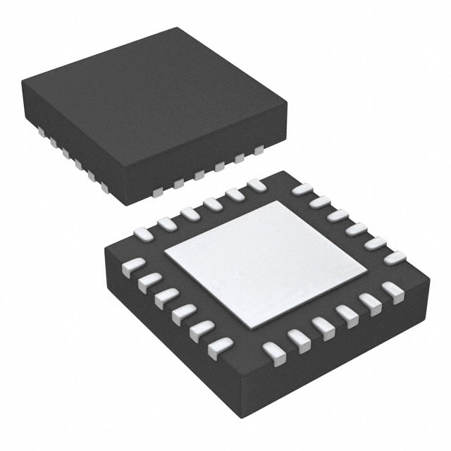


 工商网监
湘ICP备2023018690号
工商网监
湘ICP备2023018690号
