MSP430 Hardware Tools
User's Guide
Literature Number: SLAU278K
May 2009 – Revised October 2012
�Contents
....................................................................................................................................... 7
Get Started Now! ............................................................................................................... 12
1.1
Flash Emulation Tool (FET) Overview .................................................................................. 13
1.2
Kit Contents, MSP-FET430PIF .......................................................................................... 14
1.3
Kit Contents, eZ430-F2013 .............................................................................................. 14
1.4
Kit Contents, eZ430-T2012 .............................................................................................. 14
1.5
Kit Contents, eZ430-RF2500 ............................................................................................ 14
1.6
Kit Contents, eZ430-RF2500T ........................................................................................... 14
1.7
Kit Contents, eZ430-RF2500-SEH ...................................................................................... 14
1.8
Kit Contents, eZ430-Chronos-xxx ....................................................................................... 15
1.9
Kit Contents, MSP-FET430UIF .......................................................................................... 15
1.10 Kit Contents, MSP-FET430xx ............................................................................................ 15
1.11 Kit Contents, FET430F6137RF900 ..................................................................................... 16
1.12 Kit Contents, Sub-1 GHz RF Spectrum Analyzer Tool (MSP-SA430-SUB1GHZ) ................................ 16
1.13 Kit Contents, MSP-TS430xx ............................................................................................. 17
1.14 Kit Contents, EM430Fx1x7RF900 ....................................................................................... 18
1.15 Hardware Installation, MSP-FET430PIF ............................................................................... 18
1.16 Hardware Installation, MSP-FET430UIF ............................................................................... 19
1.17 Hardware Installation, eZ430-XXXX, MSP-EXP430G2, MSP-EXP430FR5739, MSP-EXP430F5529 ......... 19
1.18 Hardware Installation, MSP-FET430Uxx, MSP-TS430xxx, FET430F6137RF900, EM430Fx137RF900 ...... 19
1.19 Important MSP430 Documents on the Web ........................................................................... 19
Design Considerations for In-Circuit Programming ............................................................... 20
2.1
Signal Connections for In-System Programming and Debugging ................................................... 21
2.2
External Power ............................................................................................................. 25
2.3
Bootstrap Loader (BSL) .................................................................................................. 25
Frequently Asked Questions and Known Issues ................................................................... 26
A.1
Hardware FAQs ............................................................................................................ 27
A.2
Known Issues .............................................................................................................. 29
Hardware .......................................................................................................................... 30
B.1
MSP-TS430D8 ............................................................................................................. 32
B.2
MSP-TS430PW14 ......................................................................................................... 35
B.3
MSP-TS430L092 .......................................................................................................... 38
B.4
MSP-TS430L092 Active Cable .......................................................................................... 41
B.5
MSP-TS430PW24 ......................................................................................................... 44
B.6
MSP-TS430DW28 ......................................................................................................... 47
B.7
MSP-TS430PW28 ......................................................................................................... 50
B.8
MSP-TS430PW28A ....................................................................................................... 53
B.9
MSP-TS430DA38 .......................................................................................................... 56
B.10 MSP-TS430QFN23x0 ..................................................................................................... 59
B.11 MSP-TS430RSB40 ........................................................................................................ 62
B.12 MSP-TS430RHA40A ...................................................................................................... 65
B.13 MSP-TS430DL48 .......................................................................................................... 68
B.14 MSP-TS430RGZ48B ...................................................................................................... 71
B.15 MSP-TS430RGZ48C ...................................................................................................... 74
Preface
1
2
A
B
2
Contents
SLAU278K – May 2009 – Revised October 2012
Submit Documentation Feedback
Copyright © 2009–2012, Texas Instruments Incorporated
�www.ti.com
B.16
B.17
B.18
B.19
B.20
B.21
B.22
B.23
B.24
B.25
B.26
B.27
B.28
B.29
B.30
B.31
B.32
B.33
B.34
B.35
MSP-TS430PM64 ......................................................................................................... 77
MSP-TS430PM64A ....................................................................................................... 80
MSP-TS430RGC64B ..................................................................................................... 83
MSP-TS430RGC64C ..................................................................................................... 86
MSP-TS430RGC64USB .................................................................................................. 89
MSP-TS430PN80 .......................................................................................................... 93
MSP-TS430PN80A ........................................................................................................ 96
MSP-TS430PN80USB .................................................................................................... 99
MSP-TS430PZ100 ....................................................................................................... 103
MSP-TS430PZ100A ..................................................................................................... 106
MSP-TS430PZ100B ..................................................................................................... 109
MSP-TS430PZ100C ..................................................................................................... 112
MSP-TS430PZ5x100 .................................................................................................... 116
MSP-TS430PZ100USB ................................................................................................. 119
MSP-TS430PEU128 ..................................................................................................... 123
EM430F5137RF900 ..................................................................................................... 126
EM430F6137RF900 ..................................................................................................... 130
EM430F6147RF900 ..................................................................................................... 134
MSP-FET430PIF ......................................................................................................... 138
MSP-FET430UIF ......................................................................................................... 140
B.35.1 MSP-FET430UIF Revision History .......................................................................... 145
.............................................................................................. 146
.................................................................................................... 147
Document Revision History ........................................................................................................ 152
C
Hardware Installation Guide
C.1
Hardware Installation
SLAU278K – May 2009 – Revised October 2012
Submit Documentation Feedback
Copyright © 2009–2012, Texas Instruments Incorporated
Contents
3
�www.ti.com
List of Figures
2-1.
Signal Connections for 4-Wire JTAG Communication ................................................................ 22
2-2.
Signal Connections for 2-Wire JTAG Communication (Spy-Bi-Wire) Used by MSP430F2xx,
MSP430G2xx and MSP430F4xx Devices .............................................................................. 23
2-3.
Signal Connections for 2-Wire JTAG Communication (Spy-Bi-Wire) Used by MSP430F5xx and
MSP430F6xx Devices .................................................................................................... 24
B-1.
MSP-TS430D8 Target Socket Module, Schematic
32
B-2.
MSP-TS430D8 Target Socket Module, PCB
33
B-3.
B-4.
B-5.
B-6.
B-7.
B-8.
B-9.
B-10.
B-11.
B-12.
B-13.
B-14.
B-15.
B-16.
B-17.
B-18.
B-19.
B-20.
B-21.
B-22.
B-23.
B-24.
B-25.
B-26.
B-27.
B-28.
B-29.
B-30.
B-31.
B-32.
B-33.
B-34.
B-35.
B-36.
B-37.
B-38.
B-39.
B-40.
B-41.
B-42.
B-43.
4
...................................................................
..........................................................................
MSP-TS430PW14 Target Socket Module, Schematic ...............................................................
MSP-TS430PW14 Target Socket Module, PCB ......................................................................
MSP-TS430L092 Target Socket Module, Schematic .................................................................
MSP-TS430L092 Target Socket Module, PCB ........................................................................
MSP-TS430L092 Active Cable Target Socket Module, Schematic .................................................
MSP-TS430L092 Active Cable Target Socket Module, PCB ........................................................
MSP-TS430PW24 Target Socket Module, Schematic ...............................................................
MSP-TS430PW24 Target Socket Module, PCB ......................................................................
MSP-TS430DW28 Target Socket Module, Schematic ...............................................................
MSP-TS430DW28 Target Socket Module, PCB ......................................................................
MSP-TS430PW28 Target Socket Module, Schematic ...............................................................
MSP-TS430PW28 Target Socket Module, PCB ......................................................................
MSP-TS430PW28A Target Socket Module, Schematic ..............................................................
MSP-TS430PW28A Target Socket Module, PCB (Red) .............................................................
MSP-TS430DA38 Target Socket Module, Schematic ................................................................
MSP-TS430DA38 Target Socket Module, PCB .......................................................................
MSP-TS430QFN23x0 Target Socket Module, Schematic ...........................................................
MSP-TS430QFN23x0 Target Socket Module, PCB ..................................................................
MSP-TS430RSB40 Target Socket Module, Schematic ..............................................................
MSP-TS430RSB40 Target Socket Module, PCB .....................................................................
MSP-TS430RHA40A Target Socket Module, Schematic ............................................................
MSP-TS430RHA40A Target Socket Module, PCB ...................................................................
MSP-TS430DL48 Target Socket Module, Schematic ................................................................
MSP-TS430DL48 Target Socket Module, PCB .......................................................................
MSP-TS430RGZ48B Target Socket Module, Schematic ............................................................
MSP-TS430RGZ48B Target Socket Module, PCB ...................................................................
MSP-TS430RGZ48C Target Socket Module, Schematic ............................................................
MSP-TS430RGZ48C Target Socket Module, PCB ...................................................................
MSP-TS430PM64 Target Socket Module, Schematic ................................................................
MSP-TS430PM64 Target Socket Module, PCB .......................................................................
MSP-TS430PM64A Target Socket Module, Schematic ..............................................................
MSP-TS430PM64A Target Socket Module, PCB .....................................................................
MSP-TS430RGC64B Target Socket Module, Schematic ............................................................
MSP-TS430RGC64B Target Socket Module, PCB ...................................................................
MSP-TS430RGC64C Target Socket Module, Schematic ............................................................
MSP-TS430RGC64C Target Socket Module, PCB ...................................................................
MSP-TS430RGC64USB Target Socket Module, Schematic ........................................................
MSP-TS430RGC64USB Target Socket Module, PCB ...............................................................
MSP-TS430PN80 Target Socket Module, Schematic ................................................................
MSP-TS430PN80 Target Socket Module, PCB .......................................................................
MSP-TS430PN80A Target Socket Module, Schematic ..............................................................
List of Figures
35
36
38
39
41
42
44
45
47
48
50
51
53
54
56
57
59
60
62
63
65
66
68
69
71
72
74
75
77
78
80
81
83
84
86
87
89
90
93
94
96
SLAU278K – May 2009 – Revised October 2012
Submit Documentation Feedback
Copyright © 2009–2012, Texas Instruments Incorporated
�www.ti.com
B-44. MSP-TS430PN80A Target Socket Module, PCB ..................................................................... 97
B-45. MSP-TS430PN80USB Target Socket Module, Schematic
..........................................................
99
B-46. MSP-TS430PN80USB Target Socket Module, PCB ................................................................ 100
.............................................................
MSP-TS430PZ100 Target Socket Module, PCB ....................................................................
MSP-TS430PZ100A Target Socket Module, Schematic............................................................
MSP-TS430PZ100A Target Socket Module, PCB ...................................................................
MSP-TS430PZ100B Target Socket Module, Schematic............................................................
MSP-TS430PZ100B Target Socket Module, PCB ...................................................................
MSP-TS430PZ100C Target Socket Module, Schematic ...........................................................
MSP-TS430PZ100C Target Socket Module, PCB ..................................................................
MSP-TS430PZ5x100 Target Socket Module, Schematic ..........................................................
MSP-TS430PZ5x100 Target Socket Module, PCB..................................................................
MSP-TS430PZ100USB Target Socket Module, Schematic ........................................................
MSP-TS430PZ100USB Target Socket Module, PCB ...............................................................
MSP-TS430PEU128 Target Socket Module, Schematic ...........................................................
MSP-TS430PEU128 Target Socket Module, PCB ..................................................................
EM430F5137RF900 Target board, Schematic .......................................................................
EM430F5137RF900 Target board, PCB ..............................................................................
EM430F6137RF900 Target board, Schematic .......................................................................
EM430F6137RF900 Target board, PCB ..............................................................................
EM430F6147RF900 Target Board, Schematic ......................................................................
EM430F6147RF900 Target Board, PCB .............................................................................
MSP-FET430PIF FET Interface Module, Schematic ................................................................
MSP-FET430PIF FET Interface Module, PCB .......................................................................
MSP-FET430UIF USB Interface, Schematic (1 of 4) ...............................................................
MSP-FET430UIF USB Interface, Schematic (2 of 4) ...............................................................
MSP-FET430UIF USB Interface, Schematic (3 of 4) ...............................................................
MSP-FET430UIF USB Interface, Schematic (4 of 4) ...............................................................
MSP-FET430UIF USB Interface, PCB ................................................................................
Windows XP Hardware Wizard ........................................................................................
Windows XP Driver Location Selection Folder .......................................................................
Device Manager Using USB Debug Interface using VID/PID 0x2047/0x0010...................................
Device Manager Using USB Debug Interface with VID/PID 0x0451/0xF430 ....................................
Device Manager Using USB Debug Interface with VID/PID 0x0451/0xF432 ....................................
B-47. MSP-TS430PZ100 Target Socket Module, Schematic
103
B-48.
104
B-49.
B-50.
B-51.
B-52.
B-53.
B-54.
B-55.
B-56.
B-57.
B-58.
B-59.
B-60.
B-61.
B-62.
B-63.
B-64.
B-65.
B-66.
B-67.
B-68.
B-69.
B-70.
B-71.
B-72.
B-73.
C-1.
C-2.
C-3.
C-4.
C-5.
SLAU278K – May 2009 – Revised October 2012
Submit Documentation Feedback
Copyright © 2009–2012, Texas Instruments Incorporated
List of Figures
106
107
109
110
112
113
116
117
119
120
123
124
126
127
130
131
134
135
138
139
140
141
142
143
144
147
148
149
150
151
5
�www.ti.com
List of Tables
1-1.
Flash Emulation Tool (FET) Features and Device Compatibility .................................................... 13
1-2.
Individual Kit Contents, MSP-TS430xx ................................................................................. 17
B-1.
MSP-TS430D8 Bill of Materials .......................................................................................... 34
B-2.
MSP-TS430PW14 Bill of Materials ...................................................................................... 37
B-3.
MSP-TS430L092 Bill of Materials ....................................................................................... 40
B-4.
MSP-TS430L092 JP1 Settings .......................................................................................... 42
B-5.
MSP-TS430L092 Active Cable Bill of Materials ....................................................................... 43
B-6.
MSP-TS430PW24 Bill of Materials ...................................................................................... 46
B-7.
MSP-TS430DW28 Bill of Materials...................................................................................... 49
B-8.
.....................................................................................
MSP-TS430PW28A Bill of Materials ....................................................................................
MSP-TS430DA38 Bill of Materials ......................................................................................
MSP-TS430QFN23x0 Bill of Materials..................................................................................
MSP-TS430RSB40 Bill of Materials ....................................................................................
MSP-TS430RHA40A Bill of Materials...................................................................................
MSP-TS430DL48 Bill of Materials .......................................................................................
MSP-TS430RGZ48B Bill of Materials...................................................................................
MSP-TS430RGZ48C Revision History .................................................................................
MSP-TS430RGZ48C Bill of Materials ..................................................................................
MSP-TS430PM64 Bill of Materials ......................................................................................
MSP-TS430PM64A Bill of Materials ....................................................................................
MSP-TS430RGC64B Bill of Materials ..................................................................................
MSP-TS430RGC64C Bill of Materials ..................................................................................
MSP-TS430RGC64USB Bill of Materials...............................................................................
MSP-TS430PN80 Bill of Materials ......................................................................................
MSP-TS430PN80A Bill of Materials ....................................................................................
MSP-TS430PN80USB Bill of Materials ...............................................................................
MSP-TS430PZ100 Bill of Materials ....................................................................................
MSP-TS430PZ100A Bill of Materials ..................................................................................
MSP-TS430PZ100B Bill of Materials ..................................................................................
MSP-TS430PZ100C Bill of Materials ..................................................................................
MSP-TS430PZ5x100 Bill of Materials .................................................................................
MSP-TS430PZ100USB Bill of Materials ..............................................................................
MSP-TS430PEU128 Bill of Materials .................................................................................
EM430F5137RF900 Bill of Materials ..................................................................................
EM430F6137RF900 Bill of Materials ..................................................................................
EM430F6147RF900 Bill of Materials ..................................................................................
USB VIDs and PIDs Used in MSP430 Tools .........................................................................
B-9.
B-10.
B-11.
B-12.
B-13.
B-14.
B-15.
B-16.
B-17.
B-18.
B-19.
B-20.
B-21.
B-22.
B-23.
B-24.
B-25.
B-26.
B-27.
B-28.
B-29.
B-30.
B-31.
B-32.
B-33.
B-34.
B-35.
C-1.
6
MSP-TS430PW28 Bill of Materials
List of Tables
52
55
58
61
64
67
70
73
75
76
79
82
85
88
91
95
98
101
105
108
111
114
118
121
125
128
132
136
147
SLAU278K – May 2009 – Revised October 2012
Submit Documentation Feedback
Copyright © 2009–2012, Texas Instruments Incorporated
�Preface
SLAU278K – May 2009 – Revised October 2012
Read This First
About This Manual
This manual describes the hardware of the Texas Instruments MSP-FET430 Flash Emulation Tool (FET).
The FET is the program development tool for the MSP430 ultralow-power microcontroller. Both available
interface types, the parallel port interface and the USB interface, are described.
How to Use This Manual
Read and follow the instructions in Chapter 1. This chapter lists the contents of the FET, provides
instructions on installing the hardware and according software drivers. After you see how quick and easy it
is to use the development tools, TI recommends that you read all of this manual.
This manual describes the setup and operation of the FET but does not fully describe the MSP430™
microcontrollers or the development software systems. For details of these items, see the appropriate TI
documents listed in Section 1.19.
This manual applies to the following tools (and devices):
• MSP-FET430PIF (debug interface with parallel port connection, for all MSP430 flash-based devices)
• MSP-FET430UIF (debug interface with USB connection, for all MSP430 flash-based devices)
• eZ430-F2013 (USB stick form factor interface with attached MSP430F2013 target, for all
MSP430F20xx, MSP430G2x01, MSP430G2x11, MSP430G2x21, and MSP430G2x31 devices)
• eZ430-T2012 (three MSP430F2012 based target boards)
• eZ430-RF2500 (USB stick form factor interface with attached MSP430F2274 and CC2500 target, for
all MSP430F20xx, MSP430F21x2, MSP430F22xx, MSP430G2x01, MSP430G2x11, MSP430G2x21,
and MSP430G2x31 devices)
• eZ430-RF2500T (one MSP430F2274 and CC2500 target board including battery pack)
• eZ430-RF2500-SEH (USB stick form factor interface with attached MSP430F2274 and CC2500 target
and solar energy harvesting module)
• eZ430-Chronos-xxx (USB stick form factor interface with CC430F6137 based development system
contained in a watch. Includes
SBW ->
P1.0
P2.7/XOUT
Q1 DNP
P2.6/XIN
R3 560R
R1
330R
38
37
36
35
34
33
32
31
30
29
28
27
26
25
24
23
22
21
20
P1.7/TDO 38
P1.6/TDI 37
P1.5/TMS 36
P1.4/TCK 35
34
P1.3
33
P1.2
32
P1.1
31
P1.0
30
P2.4
29
P2.3
28
P3.7
27
P3.6
26
P3.5
25
P3.4
24
P4.7
23
P4.6
22
P4.5
21
P4.4
20
P4.3
JP6
3
2 P1.7/TDO
1
3
2
1
JP8
3
2
1
J2
P2.2
3
2
1
JP9
DNP
GND
J3
DNP
R11 0R
R10 -
DNP
Ext_PWR
P1.4/TCK
10
8
6
4
2
BOOTST
9
7
5
3
1
REV:
1.3
GND
If external supply voltage:
remove R11 and add R10 (0 Ohm)
P1.5/TMS
RST/SBWTDIO
P1.1
TEST/SBWTCK
JP7
P1.6/TDI
JTAG-Mode selection:
4-wire JTAG: Set jumpers JP4 to JP9 to position 2-3
2-wire "SpyBiWire":Set jumpers JP4 to JP9 to position 2-1
DNP GND
R5
47k C8
10nF
U1
TEST/SBWTCK P1.7/TDO
DVCC
P1.6/TDI
P2.5
P1.5/TMS
DVSS
P1.4/TCK
P2.7
P1.3
P2.6
P1.2
RST/SBWDAT
P1.1
P2.0
P1.0
P2.1
P2.4
P2.2
P2.3
P3.0
P3.7
P3.1
P3.6
P3.2
P3.5
P3.3
P3.4
AVSS
P4.7
AVCC
P4.6
P4.0 Socket:
P4.5
P4.1 Yamaichi
P4.4
P4.2 IC189-0382-037P4.3
MSP430F2274IDA
RST/SBWTDIO
TEST/SBWTCK1
2
VCC430
3
P2.5
4
GND
5
P2.7/XOUT
6
P2.6/XIN
RST/SBWTDIO7
8
P2.0
9
P2.1
10
P2.2
11
P3.0
12
P3.1
13
P3.2
14
P3.3
15
GND
16
VCC430
17
P4.0
18
P4.1
19
P4.2
JP5
3
TEST/SBWTCK 2
1
1
2
3
4
5
6
7
8
9
10
11
12
13
14
15
16
17
18
19
3
2
1
Sheet: 1/1
Copyright © 2009–2012, Texas Instruments Incorporated
JP1
2
1
JP2
C7
10uF/10V
GND
C1
12pF
DNP
D1
yellow
JP3
2
1
+
GND
MSP-TS430DA38:
MSP-TS430DA38
Target Socket Board for MSP430F2247IDA
TITLE:
Document Number:
Date: 6/18/2008 11:04:56 AM
SLAU278K – May 2009 – Revised October 2012
Submit Documentation Feedback
Hardware
56
MSP-TS430DA38
B.9
www.ti.com
MSP-TS430DA38
Figure B-17. MSP-TS430DA38 Target Socket Module, Schematic
�MSP-TS430DA38
www.ti.com
Jumpers JP4 to JP9
Close 1-2 to debug in
Spy-Bi-Wire Mode,
Close 2-3 to debug in
4-wire JTAG Mode
LED connected to P1.0
Jumper JP3
Open to disconnect LED
Orient pin 1 of
MSP430 device
Jumper JP2
Open to measure current
Connector J3
External power connector
Jumper JP1 to 'ext'
Figure B-18. MSP-TS430DA38 Target Socket Module, PCB
SLAU278K – May 2009 – Revised October 2012
Submit Documentation Feedback
Copyright © 2009–2012, Texas Instruments Incorporated
Hardware
57
�MSP-TS430DA38
www.ti.com
Table B-10. MSP-TS430DA38 Bill of Materials
Pos.
Ref Des
No. per
Board
1
C1, C2
0
12pF, SMD0805
2
C7
1
10uF, 10V, Tantal Size B
511-1463-2-ND
3
C5
1
100nF, SMD0805
478-3351-2-ND
4
C8
0
2.2nF, SMD0805
5
D1
1
green LED, SMD0603
6
J1, J2
DigiKey Part No.
Comment
DNP
DNP
475-1056-2-ND
DNP: headers and
receptacles enclosed with
kit.Keep vias free of solder.
19-pin header, TH
SAM1029-19-ND
: Header
SAM1213-19-ND
: Receptacle
7
"J3, JP1,
JP4, JP5,
JP6, JP7,
JP8, JP9"
8
3-pin header, male, TH
SAM1035-03-ND
Place jumpers on headers
JP1, JP4,JP5, JP6, JP7,
JP8, JP9; Pos 1-2
8
JP2, JP3
2
2-pin header, male, TH
SAM1035-02-ND
Place jumper on header
9
Jumper
15-38-1024-ND
Place on: JP1 - JP9; Pos 12
HRP14H-ND
9
58
0
Description
10
JTAG
1
14-pin connector, male, TH
11
BOOTST
0
10-pin connector, male, TH
12
Q1
0
Crystal
Micro Crystal MS1V-T1K
32.768kHz, C(Load) =
12.5pF
13
R1, R3
2
330 Ω, SMD0805
541-330ATR-ND
14
R10, R11
0
0 Ω, SMD0805
541-000ATR-ND
15
R5
1
47k Ω, SMD0805
541-47000ATR-ND
16
U1
1
Socket: IC189-0382--037
17
PCB
1
67 x 66 mm
18
Adhesive
Plastic feet
4
~6mm width, 2mm height
19
MSP430
2
MSP430F2274IDA
Hardware
DNP: Keep vias free of
solder
DNP: Keep vias free of
solder
DNP
Manuf.: Yamaichi
2 layers
for example, 3M Bumpons
Part No. SJ-5302
Apply to corners at bottom
side
DNP: enclosed with kit
supplied by TI
SLAU278K – May 2009 – Revised October 2012
Submit Documentation Feedback
Copyright © 2009–2012, Texas Instruments Incorporated
�MSP-TS430QFN23x0
www.ti.com
B.10 MSP-TS430QFN23x0
Figure B-19. MSP-TS430QFN23x0 Target Socket Module, Schematic
SLAU278K – May 2009 – Revised October 2012
Submit Documentation Feedback
Copyright © 2009–2012, Texas Instruments Incorporated
Hardware
59
�MSP-TS430QFN23x0
www.ti.com
Connector J5
External power connector
Jumper JP1 to 'ext'
Jumper JP2
Open to measure current
Jumper JP3
Open to disconnect LED
LED connected
to P1.0
Figure B-20. MSP-TS430QFN23x0 Target Socket Module, PCB
60
Hardware
SLAU278K – May 2009 – Revised October 2012
Submit Documentation Feedback
Copyright © 2009–2012, Texas Instruments Incorporated
�MSP-TS430QFN23x0
www.ti.com
Table B-11. MSP-TS430QFN23x0 Bill of Materials
Pos.
Ref Des
No. per
Board
1
C1, C2
0
12pF, SMD0805
2
C3
1
10uF, 10V, Tantal Size B
511-1463-2-ND
3
C4
1
100nF, SMD0805
478-3351-2-ND
4
C5
1
10nF, SMD0805
478-1383-2-ND
5
D1
1
green LED, SMD0603
475-1056-2-ND
6
J1, J2, J3,
J4
0
Description
DigiKey Part No.
Comment
DNP
DNP: headers and
receptacles enclosed with
kit.Keep vias free of solder.
10-pin header, TH
SAM1034-10-ND
: Header
SAM1212-10-ND
: Receptacle
7
J5, JP1
2
3-pin header, male, TH
SAM1035-03-ND
Place jumper on header
JP1; Pos 1-2.
8
JP2, JP3
2
2-pin header, male, TH
SAM1035-02-ND
Place jumper on header
Place on: JP1, JP2, JP3
3
Jumper
15-38-1024-ND
10
9
JTAG
1
14-pin connector, male, TH
HRP14H-ND
11
BOOTST
0
10-pin connector, male, TH
12
Q1
0
Crystal
Micro Crystal MS1V-T1K
32.768kHz, C(Load) =
12.5pF
13
R1
1
330 Ω, SMD0805
541-330ATR-ND
14
R2, R3
0
0 Ω, SMD0805
541-000ATR-ND
15
R4
1
47k Ω, SMD0805
541-47000ATR-ND
16
U1
1
Socket: QFN-40B-0.5-01
17
PCB
1
79 x 66 mm
18
Adhesive
Plastic feet
4
~6mm width, 2mm height
19
MSP430
2
MSP430F2370IRHA
DNP: Keep vias free of
solder
DNP: Keep vias free of
solder
DNP
Manuf.: Enplas
2 layers
for example, 3M Bumpons
Part No. SJ-5302
SLAU278K – May 2009 – Revised October 2012
Submit Documentation Feedback
Copyright © 2009–2012, Texas Instruments Incorporated
Apply to corners at bottom
side
DNP: enclosed with kit
supplied by TI
Hardware
61
�MSP-TS430RSB40
www.ti.com
B.11 MSP-TS430RSB40
Figure B-21. MSP-TS430RSB40 Target Socket Module, Schematic
62
Hardware
SLAU278K – May 2009 – Revised October 2012
Submit Documentation Feedback
Copyright © 2009–2012, Texas Instruments Incorporated
�MSP-TS430RSB40
www.ti.com
Connector J5
External power connector
Jumper JP1 to "ext"
Jumper JP2
Open to measure current
Jumpers JP4 to JP9
Close 1-2 to debug in Spy-Bi-Wire mode
Close 2-3 to debug in 4-wire JTAG mode
Orient Pin 1 of MSP430 device
Jumper JP3
Open to disconnect LED
D1 LED connected to P1.0
Figure B-22. MSP-TS430RSB40 Target Socket Module, PCB
SLAU278K – May 2009 – Revised October 2012
Submit Documentation Feedback
Copyright © 2009–2012, Texas Instruments Incorporated
Hardware
63
�MSP-TS430RSB40
www.ti.com
Table B-12. MSP-TS430RSB40 Bill of Materials
Ref Des
No. Per
Board
Description
1
C1, C2
0
12pF, SMD0805
2
C3, C7, C10,
C12
3
10uF, 10V, SMD 0805
445-1371-1-ND
DNP C12
3
C4, C6, C8,
C11
3
100nF, SMD0805
311-1245-2-ND
DNP C11
4
C5
1
2.2nF, SMD0805
5
C9
1
470nF, SMD0805
6
D1
1
green LED, SMD0805
Pos.
7
J1, J2, J3, J4
4
DigiKey Part No.
Comment
DNP: C1, C2
P516TR-ND
DNP: headers and
receptacles enclosed with kit.
Keep vias free of solder.
10-pin header, TH
: Header
: Receptacle
7.1
4
DNP: headers and
receptacles enclosed with kit.
Keep vias free of solder.
10-pin header, TH
: Header
: Receptacle
8
JP1,
JP4,JP5,
JP6, JP7,
JP8, JP9, J5,
JP10
9
3-pin header, male, TH
SAM1035-03-ND
Jumper: 1-2 on JP1, JP10; 23 on JP4-JP9
9
JP2, JP3
2
2-pin header, male, TH
SAM1035-02-ND
place jumper on header
10
JTAG
1
14-pin connector, male, TH
HRP14H-ND
11
BOOTST
0
10-pin connector, male, TH
12
U1
1
QFN-40B-0.4_
ENPLAS_SOCKET
Enplas
13
Q1
0
Crystal
Micro Crystal MS3V-T1R
32.768kHz, C(Load) =
12.5pF
DNP: Q1. Keep vias free of
solder
10
Jumper
15-38-1024-ND
Place on: JP1, JP2, JP3,
JP4, JP5, JP6, JP7, JP8,
JP9, JP10
15
64
16
R1,R7
2
330R SMD0805
17
R2, R3, R5,
R6, R8, R9,
R10
3
0R SMD0805
18
R4
1
47k SMD0805
19
MSP430
2
MSP430F5132
20
Rubber stand
off
4
Hardware
DNP. Keep vias free of
solder
DNP R2, R3, R5, R6
DNP: enclosed with kit. Is
supplied by TI
select appropriate; for
example, Buerklin: 20H1724
apply to corners at bottom
side
SLAU278K – May 2009 – Revised October 2012
Submit Documentation Feedback
Copyright © 2009–2012, Texas Instruments Incorporated
�MSP-TS430RHA40A
www.ti.com
B.12 MSP-TS430RHA40A
Figure B-23. MSP-TS430RHA40A Target Socket Module, Schematic
SLAU278K – May 2009 – Revised October 2012
Submit Documentation Feedback
Copyright © 2009–2012, Texas Instruments Incorporated
Hardware
65
�MSP-TS430RHA40A
www.ti.com
Connector J5
External power connector
Jumper JP1 to "ext"
Jumper JP2
Open to measure current
Jumpers JP4 to JP9
Close 1-2 to debug in Spy-Bi-Wire mode
Close 2-3 to debug in 4-wire JTAG mode
D1 LED connected to P1.0
Jumper JP3
Open to disconnect LED
Orient Pin 1 of MSP430 device
Figure B-24. MSP-TS430RHA40A Target Socket Module, PCB
66
Hardware
SLAU278K – May 2009 – Revised October 2012
Submit Documentation Feedback
Copyright © 2009–2012, Texas Instruments Incorporated
�MSP-TS430RHA40A
www.ti.com
Table B-13. MSP-TS430RHA40A Bill of Materials
Position
Ref Des
No. per
Board
1
C1, C2
0
12pF, SMD0805
DNP: C1, C2
2
C5
0
2.2nF, SMD0805
DNP C12
3
C3, C7
2
10uF, 10V, SMD0805 5
4
C4, C6
2
100nF, SMD0805
5
C9
1
470nF, SMD0805
6
D1
1
green LED, SMD0805
7
J1, J2, J3,
J4
Description
4
DigiKey Part No.
Comment
DNP C11
478-3351-2-ND
P516TR-ND
DNP: headers and receptacles
enclosed with kit. Keep vias free of
solder.
10-pin header, TH
: Header
: Receptacle
7.1
4
DNP: headers and receptacles
enclosed with kit. Keep vias free of
solder.
10-pin header, TH
: Header
: Receptacle
8
J5, JP1,
JP4, JP5,
JP6, JP7,
JP8, JP9
8
3-pin header, male, TH
SAM1035-03-ND
Place jumper on 1-2 of JP4-JP9;
Place on 1-2 on JP1
9
JP2, JP3
2
2-pin header, male, TH
SAM1035-02-ND
place jumper on header
9
Jumper
15-38-1024-ND
HRP14H-ND
10
see Pos 8 an 9
11
JTAG
1
14-pin connector, male,
TH
12
BOOTST
0
10-pin connector, male,
TH
DNP. Keep vias free of solder
13
U1
1
Socket: QFN-40B-0.5-01
Manuf.: Enplas
14
Q1
0
Crystal
15
R1,R7
2
330R SMD0805
541-330ATR-ND
16
R2, R3,
R5, R6,
R8, R9,
2
0 Ohm, SMD0805
541-000ATR-ND
17
R4
1
47k SMD0805
18
PCB
1
79 x 66 mm
19
Rubber
stand off
4
20
MSP430
2
Micro Crystal MS3V-T1R
32.768kHz, C(Load) = DNP: Q1. Keep vias free of solder
12.5pF
DNP:R2, R3, R5, R6
2 layers
select appropriate; for
example, Buerklin:
20H1724
MSP430N5736IRHA
SLAU278K – May 2009 – Revised October 2012
Submit Documentation Feedback
Copyright © 2009–2012, Texas Instruments Incorporated
apply to corners at bottom side
DNP: enclosed with kit. Is supplied by
TI
Hardware
67
�ext
int
3
2
1
JP1
C7
10uF/10V
12pF
C2
560R
R3
12pF
C1
2
1
+
2
14
12
10
8
6
4
2
13
11
9
7
5
3
1
C8
10nF
TCK
TMS
TDI
TDO
GND
1
3
5
7
9
11
13
15
17
19
21
23
2
4
6
8
10
12
14
16
18
20
22
24
R5
47K
R4
0R
J1
RST/NMI
R12
0R
VCC
C3
100nF
C4
48
47
46
45
44
43
42
41
40
39
38
37
36
35
34
33
32
31
30
29
28 P1.0
27
26
25
IC51-1387.KS-15186
P5.4
P5.3
P5.2
COM0
P2.0
P2.1
P2.2
P2.3
P2.4
P2.5
P2.6
P2.7
S5
P5.7
P5.6
P5.5
P5.0
P5.1
LCDCAP
LCDREF
P1.0
P1.1
P1.2
P1.3
1
3
5
7
9
11
13
15
17
19
21
23
10uF/10V
J3
J2
GND
2
4
6
8
10
12
14
16
18
20
22
24
Ext_PWR
BSL_TX
0R
R7 0R
R6
MSP-TS430DL48
ML10
10
8
6
4
2
BOOTST
9
7
5
3
1
BSL_RX
Vcc
ext
int
JP2
RST/NMI
TCK
REV:
1.3
Sheet: 1/1
Copyright © 2009–2012, Texas Instruments Incorporated
JTAG
ML14
J5
JP1Q
P1.0
XOUT
C5
100nF
Q1
XIN
1
JP1Q
J4
TDO/TDI
TDI/TCLK
TMS
TCK
RST/NMI
DVCC
DVSS
XIN
XOUT
AVSS
AVCC
VREF+
P6.0
P6.1
P6.2
P6.3
P6.4
P6.5
P6.6
P6.7
P1.7
P1.6
P1.5
P1.4
GND
GND
1
2
3
MSP-TS430DL48 Target Socket DL48
TITLE:
Document Number:
1
2
3
GND
D1
LED3
QUARZ3
Vcc
Q1, C1, C2
not assembled
GND
TDO 1
2
TDI
TMS 3
TCK 4
RST/NMI 5
6
GND 7
8
XIN
XOUT 9
10
11
12
13
14
15
16
17
18
19
20
21
22
23
24
U1
+
Date: 11/14/2006 1:24:44 PM
SLAU278K – May 2009 – Revised October 2012
Submit Documentation Feedback
Hardware
68
www.ti.com
MSP-TS430DL48
B.13 MSP-TS430DL48
Figure B-25. MSP-TS430DL48 Target Socket Module, Schematic
�MSP-TS430DL48
www.ti.com
Jumper J5
Open to measure current
LED connected
to P1.0
Connector J3
External power connector
Jumper JP1 to ‘ext’
Jumper J4
Open to
disconnect LED
Orient pin 1 of
MSP430 device
Figure B-26. MSP-TS430DL48 Target Socket Module, PCB
SLAU278K – May 2009 – Revised October 2012
Submit Documentation Feedback
Copyright © 2009–2012, Texas Instruments Incorporated
Hardware
69
�MSP-TS430DL48
www.ti.com
Table B-14. MSP-TS430DL48 Bill of Materials
Pos.
Ref Des
No. per
Board
1
C1, C2
0
12pF, SMD0805
2
C4, C7
2
10uF, 10V, Tantal Size B
511-1463-2-ND
3
C3, C5
2
100nF, SMD0805
478-3351-2-ND
4
C8
1
10nF, SMD0805
478-1383-2-ND
5
D1
1
yellow LED, TH, 3mm, T1
511-1251-ND
6
J1, J2
DigiKey Part No.
Comment
DNP
DNP: Headers and
receptacles enclosed with
kit.Keep vias free of solder.
24-pin header, TH
SAM1034-12-ND
: Header
SAM1212-12-ND
: Receptacle
7
J3, JP1, JP2
2
3-pin header, male, TH
SAM1035-03-ND
Place jumper on header
JP1; Pos 1-2. DNP: JP2
8
J4, J5
2
2-pin header, male, TH
SAM1035-02-ND
Place jumper on header
Place on: JP1, J4, J5
9
70
0
Description
3
Jumper
15-38-1024-ND
10
JTAG
1
14-pin connector, male, TH
HRP14H-ND
11
BOOTST
0
10-pin connector, male, TH
12
Q1
0
Crystal
Micro Crystal MS1V-T1K
32.768kHz, C(Load) =
12.5pF
13
R3
1
560 Ω, SMD0805
541-560ATR-ND
14
R4, R6, R7,
R12
2
0 Ω, SMD0805
541-000ATR-ND
15
R5
1
47k Ω, SMD0805
541-47000ATR-ND
16
U1
1
Socket: IC51-1387 KS15186
Manuf.: Yamaichi
17
PCB
1
58 x 66 mm
2 layers
18
Adhesive
Plastic feet
4
~6mm width, 2mm height
19
MSP430
2
MSP430F4270IDL
Hardware
DNP: Keep vias free of
solder
for example, 3M Bumpons
Part No. SJ-5302
DNP: Keep vias free of
solder
DNP: R6, R7
Apply to corners at bottom
side
DNP: Enclosed with kit
supplied by TI
SLAU278K – May 2009 – Revised October 2012
Submit Documentation Feedback
Copyright © 2009–2012, Texas Instruments Incorporated
�MSP-TS430RGZ48B
www.ti.com
B.14 MSP-TS430RGZ48B
Figure B-27. MSP-TS430RGZ48B Target Socket Module, Schematic
SLAU278K – May 2009 – Revised October 2012
Submit Documentation Feedback
Copyright © 2009–2012, Texas Instruments Incorporated
Hardware
71
�MSP-TS430RGZ48B
www.ti.com
Connector J5
External power connector
Jumper JP1 to "ext"
Jumpers JP5 to JP10
Close 1-2 to debug in Spy-Bi-Wire mode
Close 2-3 to debug in 4-wire JTAG mode
Jumper JP1
Open to measure current
Orient Pin 1 of MSP430 device
Jumper JP2
Open to disconnect LED
D1 LED connected to P1.0
Figure B-28. MSP-TS430RGZ48B Target Socket Module, PCB
72
Hardware
SLAU278K – May 2009 – Revised October 2012
Submit Documentation Feedback
Copyright © 2009–2012, Texas Instruments Incorporated
�MSP-TS430RGZ48B
www.ti.com
Table B-15. MSP-TS430RGZ48B Bill of Materials
Position
Ref Des
No. per
Board
1
C1, C2
0
12pF, SMD0805
DNP
2
C3, C4
0
47pF, SMD0805
DNP
3
C6, C7,
C12
3
10uF, 6.3V, SMD0805
4
C5, C11,
C13, C14
4
100nF, SMD0805
5
C8
1
2.2nF, SMD0805
6
C9
1
470nF, SMD0805
478-1403-2-ND
7
D1
1
green LED, SMD0805
P516TR-ND
8
J1, J2, J3,
J4
0
12-pin header, TH
SAM1029-12-ND
(Header) SAM1213-12ND (Receptacle)
DNP: Headers and receptacles
enclosed with kit. Keep vias free of
solder:
9
J5
1
3-pin header, male, TH
10
JP3, JP5,
JP6, JP7,
JP8, JP9,
JP10
7
3-pin header, male, TH
SAM1035-03-ND
place jumpers on pins 2-3 on JP5,
JP6, JP7, JP8, JP9, JP10 place
jumpers on pins 1-2 on JP3,
11
JP1, JP2
2
2-pin header, male, TH
SAM1035-02-ND
Place jumper on header
9
Jumper
15-38-1024-ND
See Pos. 10and Pos. 11
HRP14H-ND
12
Description
DigiKey Part No.
Comment
311-1245-2-ND
13
JTAG
1
14-pin connector, male,
TH
14
BOOTST
0
10-pin connector, male,
TH
15
Q1
0
Crystal
Micro Crystal MS3V-T1R
32.768kHz, C(Load) =
DNP: Q1 Keep vias free of solder
12.5pF
16
Q2
0
Crystal
Q2: 4MHz Buerklin:
78D134
17
Insulating
disk to Q2
0
Insulating disk to Q2
http://www.ettinger.de/Ar
t_Detail.cfm?ART_ART
NUM=70.08.121
18
R3, R7
2
330 Ω, SMD0805
541-330ATR-ND
19
R1, R2,
R4, R6,
R8,
R9,R10,
R11, R12
3
0 Ohm, SMD0805
541-000ATR-ND
20
R5
1
47k Ω, SMD0805
541-47000ATR-ND
21
U1
1
Socket: QFN11T048008_A101121_RGZ48
22
PCB
1
81 x 76 mm
23
Adhesive
plastic feet
4
Approximately 6mm
width, 2mm height
24
MSP430
2
MSP430F5342IRGZ
"DNP Keep vias free of solder"
DNP: Q2 Keep vias free of solder
DNP: R6, R8, R9, R10, R11,R12
Manuf.: Yamaichi
2 layers
for example, 3M
Bumpons Part No. SJ5302
SLAU278K – May 2009 – Revised October 2012
Submit Documentation Feedback
Copyright © 2009–2012, Texas Instruments Incorporated
Apply to corners at bottom side
DNP: enclosed with kit, supplied by TI
Hardware
73
�Vcc
ext
int
J1
3
2
1
VCC
14
12
10
8
6
4
2
JTAG
13
11
9
7
5
3
1
GND
TEST/SBWTCK1
R7
0R
TEST/SBWTCK
JP4
3
2
1
DNP
GND
EVQ11
JP5
3
2 PJ.0/TDO
1
DNP
DVSS 12
P4.6 11
P4.5 10
P4.4 9
P1.7 8
P1.6 7
P3.7 6
P3.6 5
P3.5 4
P3.4 3
P2.2 2
P2.1 1
DNP
C9
JP7
GND
9
7
5
3
1
JP8
GND
J2
Ext_PWR
3
2 PJ.3/TCK
1
100nF
C6
DVCC
1uF/10V
DNP
C7
GND
10
8
6
4
2
DNP
If external supply voltage:
remove R3 and add R2 (0 Ohm)
DNP
BOOTST
3
2 PJ.2/TMS
1
HFGND
RST/SBWTDIO
P2.0
TEST/SBWTCK
P2.1
DNP
C8
DNP
JP6
SV2
3
2 PJ.1/TDI
1
JTAG-Mode selection:
4-wire JTAG: Set jumpers JP3 to JP8 to position 2-3
2-wire "SpyBiWire": Set jumpers JP3 to JP8 to position 1-2
SW1
1.1nF
C5
RST/SBWTDIO
47k
R4
HFXOUT
HFXIN
36
35
34
33
32
31
30
29
28
27
26
25
3
2
1
RST/NMI
JP3
3
2
1
TCK/SBWTCK
TMS
TDI
TDO/SBWTDIO
JTAG ->
U1
36_DVSS
35_P4.6
34_P4.5
33_P4.4
32_P1.7
31_P1.6
30_P3.7
29_P3.6
28_P3.5
27_P3.4
26_P2.2
25_P2.1
Target Socket Board for MSP430FR58xx, FR59xx IRGZ
MSP-TS430RGZ48C
1.3
Copyright © 2009–2012, Texas Instruments Incorporated
SBW ->
C2
DNP
LFXIN
LFXOUT
SV1
1_P1.0
2_P1.1
3_P1.2
4_P3.0
5_P3.1
6_P3.2
7_P3.3
8_P4.7
9_P1.3
10_P1.4
11_P1.5
12_PJ.0_TDO
QUARZ5
Q2
2
1
C4
DNP
1
P1.0
2
P1.1
3
P1.2
4
P3.0
5
P3.1
6
P3.2
7
P3.3
8
P4.7
9
P1.3
10
P1.4
11
P1.5
PJ.0/TDO 12
R8
0R
R9
0R
DVCC
AVCC
100nF
1
2
3
4
5
6
7
8
9
10
11
12
12
11
10
9
8
7
6
5
4
3
2
1
2
1
1uF/10V
C3
SV4
Q1
LFGND QUARZ5
DNP
C1
DNP
P1.3
P1.2
P1.1
P1.0
0R
R6
0R
R5
JP1
JP2
GND
DVCC
connection by via
AVSS
JP11
JP10
JP9
R2
-
R3
0R
0R R12
DVSS
DNP
SW2
0R R13
R14DNP
R11 DNP
D3
red (DNP)
R10DNP
R1 330R
D2
yellow (DNP)
D1
green
GND
SV3
TP1TP2
48 AVCC
47 AVSS
46
45
44 AVSS
43
42
41 AVSS
40 P2.4
39 P2.3
38 P2.7
37 DVCC
48_AVCC
47_AVSS
46_LFXOUT
45_LFXIN
44_AVSS
43_HFXOUT
42_HFXIN
41_AVSS
40_P2.4
39_P2.3
38_P2.7
37_DVCC
13_PJ.1_TDI
14_PJ.2_TMS
15_PJ.3/TCK
16_P4.0
17_P4.1
18_P4.2
19_P4.3
20_P2.5
21_P2.6
22_TEST/SBWTCK
23_RST/SBWTDIO
24_P2.0
1 PJ.1/TDI
13
2 PJ.2/TMS
14
3 PJ.3/TCK
15
4 P4.0
16
17
5 P4.1
18
6 P4.2
19
7 P4.3
20
8 P2.5
21
9 P2.6
10 TEST/SBWTCK22
11 RST/SBWTDIO23
24
12 P2.0
2
1
2
1
2
1
SLAU278K – May 2009 – Revised October 2012
Submit Documentation Feedback
Hardware
74
www.ti.com
MSP-TS430RGZ48C
B.15 MSP-TS430RGZ48C
Figure B-29. MSP-TS430RGZ48C Target Socket Module, Schematic
�MSP-TS430RGZ48C
www.ti.com
Figure B-30. MSP-TS430RGZ48C Target Socket Module, PCB
Table B-16. MSP-TS430RGZ48C Revision History
Revision
Comments
1.2
Initial release
1.3
LFOSC pins swapped at SV1 (9-10).
HFOSC pins swapped at SV1 (6-7).
BOOTST pin 4 now directly connected to the device RST/SBWTDIO pin.
SLAU278K – May 2009 – Revised October 2012
Submit Documentation Feedback
Copyright © 2009–2012, Texas Instruments Incorporated
Hardware
75
�MSP-TS430RGZ48C
www.ti.com
Table B-17. MSP-TS430RGZ48C Bill of Materials
Pos
1
Ref Des
SV1, SV2, SV3,
SV4
Number
Per
Board
4
Description
DigiKey Part Number
12-pin header, TH
Comment
DNP: headers and receptacles enclosed with kit.
Keep vias free of solder.
SAM1029-12-ND
: Header
: Receptacle
1.1
SV1, SV2, SV3,
SV4
4
12-pin receptable, TH
DNP: headers and receptacles enclosed with kit.
Keep vias free of solder.
: Header
76
SAM1213-12-ND
: Receptacle
2
JP1, JP2, JP9
3
2-pin header, male, TH
SAM1035-02-ND
Place jumper on header
3
JP10, JP11
2
2-pin header, male, TH
SAM1035-02-ND
DNP
4
J1, JP3, JP4, JP5,
JP6, JP7, JP8
7
3-pin header, male, TH
SAM1035-03-ND
Place jumpers on pins 2-3
5
J2
1
3-pin header, male, TH
SAM1035-03-ND
6
JP1, JP2, JP9, J1,
JP3, JP4, JP5,
JP6, JP7, JP8
10
Jumper
15-38-1024-ND
7
R2, R3, R5, R6,
R8, R9, R10, R11,
R14
9
DNP, 0805
8
R12, R13, R7
3
0R, 0805
541-000ATR-ND
9
C5
1
1.1nF, CSMD0805
490-1623-2-ND
10
C3, C7
2
1uF, 10V, CSMD0805
490-1702-2-ND
11
R4
1
47k, 0805
541-47000ATR-ND
12
C4, C6
2
100nF, CSMD0805
311-1245-2-ND
13
R1
1
330R, 0805
541-330ATR-ND
14
C1, C2, C8, C9
4
DNP, CSMD0805
15
SW1, SW2
2
EVQ-11L05R
P8079STB-ND
DNP, Lacon: 1251459
16
BOOTST
1
10-pin connector, male, TH
HRP10H-ND
DNP, keep vias free of solder
17
JTAG
1
14-pin connector, male, TH
HRP14H-ND
18
Q1
1
DNP: MS3V-TR1 (32768kHz,
20ppm, 12.5pF)
depends on application
Micro Crystal, DNP, enclosed in kit, keep vias
free of solder
19
Q2
1
DNP, Christal
depends on application
DNP, keep vias free of solder
20
U1
1
Socket: QFN11T048-008
A101121-001
Manuf.: Yamaichi
20.1
U1
1
MSP430
DNP: enclosed with kit. Is supplied by TI.
21
D1
1
green LED, DIODE0805
22
D3
1
red (DNP), DIODE0805
DNP
23
D2
1
yellow (DNP), DIODE0805
DNP
24
TP1, TP2
2
Testpoint
25
Rubber stand off
4
26
PCB
1
Hardware
79.6 x 91.0 mm
Place on: JP1, JP2, JP9, J1, JP3, JP4, JP5, JP6,
JP7, JP8
DNP
DNP
P516TR-ND
DNP, keep pads free of solder
Buerklin: 20H1724
apply to corners at bottom side
MSP-TS430RGZ48C
Rev. 1.2
2 layers, black solder mask
SLAU278K – May 2009 – Revised October 2012
Submit Documentation Feedback
Copyright © 2009–2012, Texas Instruments Incorporated
�MSP-TS430PM64
www.ti.com
B.16 MSP-TS430PM64
12pF
C2
not assembled
R9
12pF
C1
R3
R4
2
14
12
10
8
6
4
2
1
13
11
9
7
5
3
1
J1
1
2
3
4
5
6
7
8
9
10
11
12
13
14
15
16
100nF
1
0R
R2
DVCC
2
3
4
5
6
7
XIN
XOUT
10
11
12
13
14
15
16
VCC
TCK
TMS
TDI
TDO
C8
R5
U2
MSP64PM
Socket:
Yamaichi
IC51-0644-807
RST/NMI
48
47
46
45
44
43
42
41
40
39
38
37
36
35
34
33
C3
12pF
not assembled
C4
12pF
48
47
46
45
44
43
42
41
40
39
38
37
36
35
34
33
J3
10
8
6
4
2
BOOTST
9
7
5
3
1
ML10
not assembled
J5
TITLE:
MSP-TS430PM64
Document Number:
PWR3
GND
1
2
3
For BSL usage add:
R11 0R
R6 R7 R13 R14
MSP430F14x : 0 0 open open
MSP430F41x : open open 0 0
If external supply voltage:
remove R11 and add R10 (0 Ohm)
R10 -
REV:
1.2
Sheet: 1/1
MSP-TS430PM64 Target Socket PM64
for F14x and F41x
FE16-1-3
GND
Date: 3/14/2006 10:46:30 AM
Copyright © 2009–2012, Texas Instruments Incorporated
10nF
47K
77
Hardware
SLAU278K – May 2009 – Revised October 2012
Submit Documentation Feedback
JTAG
ML14
J6
JP1Q
Open J6 if LCD
is connected
560R
2
remove R8 and add R9 (0 Ohm)
If external supply voltage:
GND
C5
FE16-1-1
0R
0R
0R
R14
0R
R7
R13
R6
FE16-1-4
XTCLK
J2
C7
+
R1 0R
64
63
62
61
60
59
58
57
56
55
54
53
52
51
50
49
AVCC
DVSS
AVSS
61
60
59
RST
TCK
TMS
TDI
TDO
53
52
51
50
49
17
18
19
20
21
22
23
24
25
26
27
28
29
30
31
32
17
18
19
20
21
22
23
24
25
26
27
28
29
30
31
32
10uF/10V
10uF/6,3V
+
C6
JP1Q
not assembled
J7
1
J4
FE16-1-2
-
LFXTCLK
0R
R12
Q1
-
R8
reserved for
future
enhancement
LED3
D1
NOTE: Connections between the JTAG header and pins XOUT and XIN are no longer required and should not be
made.
Figure B-31. MSP-TS430PM64 Target Socket Module, Schematic
�MSP-TS430PM64
www.ti.com
Connector J5
External power connection
Remove R8 and jumper R9
LED connected
to pin 12
Jumper J7
Open to measure current
Jumper J6
Open to disconnect LED
Orient Pin 1 of
MSP430 device
Figure B-32. MSP-TS430PM64 Target Socket Module, PCB
78
Hardware
SLAU278K – May 2009 – Revised October 2012
Submit Documentation Feedback
Copyright © 2009–2012, Texas Instruments Incorporated
�MSP-TS430PM64
www.ti.com
Table B-18. MSP-TS430PM64 Bill of Materials
Pos.
Ref Des
No. per
Board
1
C1, C2
0
12pF, SMD0805
DNP
1.1
C3, C4
0
47pF, SMD0805
DNP: Only recommendation.
Check your crystal spec.
2
C6, C7
1
10uF, 10V, Tantal Size B
511-1463-2-ND
3
C5
1
100nF, SMD0805
478-3351-2-ND
4
C8
1
10nF, SMD0805
478-1383-2-ND
5
C9
1
470nF, SMD0805
478-1403-2-ND
6
D1
1
green LED, SMD0805
P516TR-ND
7
J1, J2, J3, J4
Description
0
DigiKey Part No.
Comment
DNP: C6
DNP: Headers and
receptacles enclosed with
kit.Keep vias free of solder.
16-pin header, TH
SAM1029-16-ND
: Header
SAM1213-16-ND
: Receptacle
8
J5
1
3-pin header, male, TH
SAM1035-03-ND
9
J6, J7
2
2-pin header, male, TH
SAM1035-02-ND
Place jumper on header
2
Jumper
15-38-1024-ND
Place on: J6, J7
HRP14H-ND
11
12
JTAG
1
14-pin connector, male, TH
13
BOOTST
0
10-pin connector, male, TH
14
Q1, Q2
0
Crystal
Q1: Micro Crystal MS1V-T1K
DNP: Keep vias free of
32.768kHz, C(Load) =
solder
12.5pF
15
R3
1
330 Ω, SMD0805
541-330ATR-ND
16
R1, R2, R4,
R6, R7, R8,
R9, R10,
R11, R12,
R13, R14
3
0 Ω, SMD0805
541-000ATR-ND
17
R5
1
47k Ω, SMD0805
541-47000ATR-ND
18
U1
1
Socket: IC51-0644-807
Manuf.: Yamaichi
19
PCB
1
78 x 75 mm
2 layers
20
Rubber
standoff
4
21
MSP430
22
DNP: Keep vias free of
solder
select appropriate
MSP430F2619IPM
MSP430F417IPM
SLAU278K – May 2009 – Revised October 2012
Submit Documentation Feedback
Copyright © 2009–2012, Texas Instruments Incorporated
DNP: R4, R6, R7, R9, R10,
R11, R12, R13, R14
Apply to corners at bottom
side
DNP: Enclosed with kit
supplied by TI
Hardware
79
�Vcc
3
2
ext
1
int
JP3
2
1
JP2
14
12
10
8
6
4
2
R2
0R
JTAG
C5
100nF
13
11
9
7
5
3
1
DNP
GND
J4
R6
330R
3
TEST/SBWTCK 2
A
1
JP5
RST/NMI
VCC
TCK/SBWTCK
TMS
TDI
TDO/SBWTDIO
3
2
1
JP4
AVCC
AVSS
Socket:
Yamaichi
IC51-0644-807
DNP GND
R4
47k C3
2.2nF
VCC430
RST/SBWTDIO
B
P1.0
P1.1
48
47
46
45
44
43
42
41
40
39
38
37
36
35
34
33
48
47
46
45
44
43
42
41
40
39
38
37
36
35
34
33
3
2 P7.0/TDO
1
C
JP6
J3
3
2
1
JP7
P7.1/TDI
D
DNP
R13
0R
TEST/SBWTCK
A
ADD LCD-CAP!
P5.1
3
2 P7.2/TMS
1 E
JP8
DNP
9
7
5
3
1
DNP
R11
0R
DNP
RST/SBWTDIO
B
DNP
R10
0R
PWR3
GND
1
2
3
3
2 P7.3/TCK
1 F
JP9
10
8
6
4
2
R14
0R BOOTST
GND
J5
Sheet: 1/1
REV:
1.1
If supplied by interface: populate R11 (0R), remove R10
If supplied locally: populate R10 (0R), remove R11
MSP-TS430PM64A
MSP-TS430PM64A Target Socket
for F4152
TITLE:
Document Number:
Date: 3/29/2011 3:07:02 PM
Copyright © 2009–2012, Texas Instruments Incorporated
JTAG ->
1
2
3
4
5
6
7
8
9
10
11
12
13
14
15
16
SBW ->
AVCC
J1
VCC430
AVSS
C4
100nF
0R
R7
XIN
Q1
1
2
3
4
5
6
7
8
9
10
11
12
13
14
15
16
GND
J2
A
B
F
E
D
C
VCC430
C6
10uF/6.3V
R1 0R
DNP
12pF
C2
DNP
R5
0R
XOUT
DNP
R3
P5.1
330R
JP1
Open JP1 if LCD
is connected
DNP
12pF
C1
XTLGND
GND
D1
2
1
+
GND
1
2
64
63
62
61
60
59
58
57
56
55
54
53
52
51
50
49
64
63
62
61
60
59
58
57
56
55
54
53
52
51
50
49
17
18
19
20
21
22
23
24
25
26
27
28
29
30
31
32
17
18
19
20
21
22
23
24
25
26
27
28
29
30
31
32
SLAU278K – May 2009 – Revised October 2012
Submit Documentation Feedback
Hardware
80
www.ti.com
MSP-TS430PM64A
B.17 MSP-TS430PM64A
Figure B-33. MSP-TS430PM64A Target Socket Module, Schematic
�MSP-TS430PM64A
www.ti.com
Jumper JP3
1-2 (int): Power supply via JTAG interface
2-3 (ext): External Power Supply
Jumper JP4 to JP9:
Close 1-2 to debug in Spy-Bi-Wire mode
Close 2-3 to debug in 4-wire JTAG mode
Jumper JP2
Open to measure current
Orient Pin 1 of Device
Jumper JP1
Open to disconnect LED
LED D1 connected to P5.1
Figure B-34. MSP-TS430PM64A Target Socket Module, PCB
SLAU278K – May 2009 – Revised October 2012
Submit Documentation Feedback
Copyright © 2009–2012, Texas Instruments Incorporated
Hardware
81
�MSP-TS430PM64A
www.ti.com
Table B-19. MSP-TS430PM64A Bill of Materials
Pos.
Ref Des
No. per
Board
1
C1, C2,
0
12pF, SMD0805
DNP
2
C3
0
2.2nF, SMD0805
DNP
3
C6,
1
10uF, 10V, Tantal Size B
511-1463-2-ND
4
C4, C5
2
100nF, SMD0805
478-3351-2-ND
5
D1
1
green LED, SMD0805
P516TR-ND
6
J1, J2, J3, J4
DigiKey Part No.
Comment
DNP: Headers and
receptacles enclosed with kit.
Keep vias free of solder.
16-pin header, TH
SAM1029-16-ND
: Header
SAM1213-16-ND
: Receptacle
7
J5, JP3, JP4,
JP5, JP6,
JP7, JP8,
JP9
8
3-pin header, male, TH
SAM1035-03-ND
8
JP1, JP2
2
2-pin header, male, TH
SAM1035-02-ND
Place jumper on header
2
Jumper
15-38-1024-ND
Place on: J6, J7
HRP14H-ND
9
82
0
Description
10
JTAG
1
14-pin connector, male, TH
11
BOOTST
0
10-pin connector, male, TH
12
Q1
0
Crystal
Micro Crystal MS1V-T1K
32.768kHz, C(Load) =
12.5pF
13
R3, R6
2
330 Ω, SMD0805
541-330ATR-ND
14
R1, R2, R5,
R7, R9, R10,
R11, R13,
R14
2
0 Ω, SMD0805
541-000ATR-ND
15
R4
1
47k Ω, SMD0805
541-47000ATR-ND
16
U1
1
Socket: IC51-0644-807
Manuf.: Yamaichi
17
PCB
1
78 x 75 mm
4 layers
18
Rubber stand
off
4
19
MSP430
2
Hardware
DNP: Keep vias free of
solder
select appropriate
DNP: Keep vias free of
solder
DNP: R5, R7, R9, R10, R11,
R13, R14
Apply to corners at bottom
side
DNP: Enclosed with kit
supplied by TI
MSP430F4152IPM
SLAU278K – May 2009 – Revised October 2012
Submit Documentation Feedback
Copyright © 2009–2012, Texas Instruments Incorporated
�MSP-TS430RGC64B
www.ti.com
B.18 MSP-TS430RGC64B
Figure B-35. MSP-TS430RGC64B Target Socket Module, Schematic
SLAU278K – May 2009 – Revised October 2012
Submit Documentation Feedback
Copyright © 2009–2012, Texas Instruments Incorporated
Hardware
83
�MSP-TS430RGC64B
www.ti.com
Connector J5
External power connector
Jumper JP3 to "ext"
Jumpers JP5 to JP10
Close 1-2 to debug in Spy-Bi-Wire mode
Close 2-3 to debug in 4-wire JTAG mode
If the system should
be supplied via LDOI (J6),
close JP4 and
set JP3 to external
Orient Pin 1 of MSP430 device
D1 LED connected to P1.0
Jumper JP2
Open to disconnect LED
Figure B-36. MSP-TS430RGC64B Target Socket Module, PCB
84
Hardware
SLAU278K – May 2009 – Revised October 2012
Submit Documentation Feedback
Copyright © 2009–2012, Texas Instruments Incorporated
�MSP-TS430RGC64B
www.ti.com
Table B-20. MSP-TS430RGC64B Bill of Materials
Pos.
Ref Des
No. per
Board
1
C1, C2
0
12pF, SMD0805
DNP
2
C3, C4
0
47pF, SMD0805
DNP
3
C6, C7, C10
3
10uF, 6.3V, SMD0805
4
C5, C11,
C13, C14,
C15
5
100nF, SMD0805
5
C8
1
2.2nF, SMD0805
6
C9
1
470nF, SMD0805
7
C16
1
4.7uF, SMD0805
8
C17
1
220nF, SMD0805
9
D1
1
green LED, SMD0805
P516TR-ND
10
J1, J2, J3,
J4
0
16-pin header, TH
SAM1029-16-ND
(Header) SAM1213-16ND (Receptacle)
DNP: Headers and receptacles
enclosed with kit. Keep vias free of
solder:
11
J5 , J6
2
3-pin header, male, TH
12
JP3, JP5,
JP6, JP7,
JP8, JP9,
JP10
7
3-pin header, male, TH
SAM1035-03-ND
place jumpers on pins 2-3 on JP5, JP6,
JP7, JP8, JP9, JP10 place jumpers on
pins 1-2 on JP3,
13
JP1, JP2,
JP4
3
2-pin header, male, TH
SAM1035-02-ND
Place jumper on header
10
Jumper
15-38-1024-ND
See Pos. 12 and Pos. 13
HRP14H-ND
14
Description
DigiKey Part No.
Comment
311-1245-2-ND
478-1403-2-ND
15
JTAG
1
14-pin connector, male,
TH
16
BOOTST
0
10-pin connector, male,
TH
17
Q1
0
Crystal
Micro Crystal MS3V-T1R
32.768kHz, C(Load) =
12.5pF
DNP: Q1 Keep vias free of solder
18
Q2
0
Crystal
Q2: 4MHz Buerklin:
78D134
DNP: Q2 Keep vias free of solder
19
Insulating
disk to Q2
0
Insulating disk to Q2
http://www.ettinger.de/Art
_Detail.cfm?ART_ARTNU
M=70.08.121
20
R3, R7
2
330 Ω, SMD0805
541-330ATR-ND
21
R1, R2, R4,
R6, R8,
R9,R10,
R11, R12
3
0 Ohm, SMD0805
541-000ATR-ND
22
R5
1
47k Ω, SMD0805
541-47000ATR-ND
23
U1
1
Socket: QFN11T064-006N-HSP
24
PCB
1
85 x 76 mm
25
Adhesive
plastic feet
26
D3,D4
27
MSP430
4
Approximately 6mm
width, 2mm height
2
MSP430F5310 RGC
"DNP Keep vias free of solder"
DNP: R6, R8, R9, R10, R11,R12
Manuf.: Yamaichi
2 layers
for example, 3M
Bumpons Part No. SJ5302
SLAU278K – May 2009 – Revised October 2012
Submit Documentation Feedback
Copyright © 2009–2012, Texas Instruments Incorporated
Apply to corners at bottom side
DNP: enclosed with kit, supplied by TI
Hardware
85
�A
13
11
9
7
5
3
1
RST/NMI
GND
TCK
TMS
TDI
TDO
TCK
2
3
1
2
3
JP8
4
THERMAL_4
tbd
C4
5
S.G.
9
7
5
3
1
J6
1
2
3
6
J5
0R
DVCC
1
2
Size:
0R
1.1
MSP430
Tools
TI Friesing
Revision:
Mentor Pads Logic V9
6
R11
PINHEAD_1X2
JP4
PINHEAD_1X3
GND
GND
BSL
CN-ML10
0 1
8
6
4
2
BOOTST
C16
GND
C15
4.7uF
1
MSP-TS430RGC64C
100nF
GND
Comment:
PINHEAD_1X3
3
2
1
DVIO Power Circle
P1.2/TA0.1
P1.1/TA0.0
TEST/SBWTCK
GND
Name:
SHORTCUT2
J3
12/14/10
Date:
16
15
14
13
12
11
10
9
8
7
6
5
4
3
2
1
tbd C3 XTLGND2
JP9
JP10
1
1
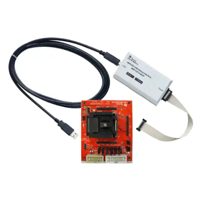


 工商网监
湘ICP备2023018690号
工商网监
湘ICP备2023018690号
