®
OPA2544
FPO
High-Voltage, High-Current
DUAL OPERATIONAL AMPLIFIER
FEATURES
DESCRIPTION
● HIGH OUTPUT CURRENT: 2A min
● WIDE POWER SUPPLY RANGE:
±10V to ±35V
The OPA2544 is a dual high-voltage/high-current operational amplifier suitable for driving a wide variety
of high power loads. It provides 2A output current and
power supply voltage range extends to ±35V.
● SLEW RATE: 8V/µs
● INTERNAL CURRENT LIMIT
The OPA2544 integrates two high performance FET
op amps with high power output stages on a single
monolithic chip. Internal current limit and thermal
shutdown protect the amplifier and load from damage.
● THERMAL SHUTDOWN PROTECTION
● FET INPUT: IB = 50pA max
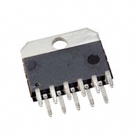
● 11-LEAD PLASTIC PACKAGE
The OPA2544 is available in a 11-lead plastic
packages and is specified for the –40°C to +85°C
temperature range.
APPLICATIONS
● MOTOR DRIVER
● PROGRAMMABLE POWER SUPPLY
● SERVO AMPLIFIER
● VALVES, ACTUATOR DRIVER
● MAGNETIC DEFLECTION COIL DRIVER
● AUDIO AMPLIFIER
Case
connected
to V– Supply.
A
B
1
11
NC
V+
V–
International Airport Industrial Park • Mailing Address: PO Box 11400, Tucson, AZ 85734 • Street Address: 6730 S. Tucson Blvd., Tucson, AZ 85706 • Tel: (520) 746-1111 • Twx: 910-952-1111
Internet: http://www.burr-brown.com/ • FAXLine: (800) 548-6133 (US/Canada Only) • Cable: BBRCORP • Telex: 066-6491 • FAX: (520) 889-1510 • Immediate Product Info: (800) 548-6132
®
© 1994 Burr-Brown Corporation
SBOS037
PDS-1249C
1
OPA2544
Printed in U.S.A. March, 1998
�SPECIFICATIONS
At TCASE = +25°C and VS = ±35V, unless otherwise noted.
OPA2544T
PARAMETER
CONDITIONS
OFFSET VOLTAGE
Input Offset Voltage
vs Temperature
vs Power Supply
INPUT BIAS CURRENT(1)
Input Bias Current
vs Temperature
Input Offset Current
MIN
Specified Temp. Range
VS = ±10V to ±35V
VCM = 0V
Linear Operation
Linear Operation
VCM = ±VS – 6V
(V+) –6
(V–) +6
90
INPUT IMPEDANCE
Differential
Common-Mode
OPEN-LOOP GAIN
Open-Loop Voltage Gain
FREQUENCY RESPONSE
Gain-Bandwidth Product
Slew Rate
Full-Power Bandwidth
Settling Time 0.1%
Total Harmonic Distortion
OUTPUT
Voltage Output: Positive
Negative
Positive
Negative
Current Output
Short-Circuit Current
POWER SUPPLY
Specified Operating Voltage
Operating Voltage Range
Quiescent Current (total)
TEMPERATURE RANGE
Operating Range
Storage
Thermal Resistance, θJC2
Thermal Resistance, θJC2
Thermal Resistance, θJC2
Thermal Resistance, θJC2
Thermal Resistance, θJA2
MAX
UNITS
±1
±10
±10
±5
±100
mV
µV/°C
µV/V
±50
pA
±50
pA
±15
Doubles every 10˚C
±10
VCM = 0V
NOISE
Input Voltage Noise
Noise Density, f = 1kHz
Current Noise Density, f = 1kHz
INPUT VOLTAGE RANGE
Common-Mode Input Range
Positive
Negative
Common-Mode Rejection
TYP
VO = ±30V, RL = 15Ω
90
RL = 15Ω
60Vp-p, RL = 15Ω
5
G = –10, 60V Step
IO = 2A
IO = 2A
IO = 0.5A
IO = 0.5A
(V+) –5
(V–) +5
(V+) –4.2
(V–) +4
±10
IO = 0
36
3
nV/√Hz
fA/√Hz
(V+) –4
(V–) +4
106
V
V
dB
1012 || 8
1012 || 10
Ω || pF
Ω || pF
103
dB
1.4
8
See Typical Curve
25
See Typical Curve
MHz
V/µs
(V+) –4.4
(V–) +3.8
(V+) –3.8
(V–) +3.1
See SOA Curves
±4
V
V
V
V
±35
±22
–40
–40
Both Amplifiers, f > 50Hz
Both Amplifiers, DC
One Amplifier, f > 50Hz
One Amplifier, DC
No Heat Sink
µs
A
±35
±30
+85
+125
2
2.5
2.7
3
30
V
V
mA
°C
°C
°C/W
°C/W
°C/W
°C/W
°C/W
NOTES: (1) High-speed test at TJ = +25°C. (2) Calculated from total power dissipation of both amplifiers.
The information provided herein is believed to be reliable; however, BURR-BROWN assumes no responsibility for inaccuracies or omissions. BURR-BROWN assumes
no responsibility for the use of this information, and all use of such information shall be entirely at the user’s own risk. Prices and specifications are subject to change
without notice. No patent rights or licenses to any of the circuits described herein are implied or granted to any third party. BURR-BROWN does not authorize or warrant
any BURR-BROWN product for use in life support devices and/or systems.
®
OPA2544
2
�ABSOLUTE MAXIMUM RATINGS(1)
CONNECTION DIAGRAM
Front View
11-Lead Plastic
Supply Voltage, V+ to V– ................................................................... 70V
Output Current ................................................................. See SOA Curve
Input Voltage .................................................... (V–) –0.7V to (V+) +0.7V
Operating Temperature ................................................. –55°C to +125°C
Storage Temperature ..................................................... –40°C to +125°C
Junction Temperature ...................................................................... 150°C
Lead Temperature (soldering, –10s) ............................................... 300°C
Case
connected
to V– Supply.
A
NOTE: (1) Stresses above these ratings may cause permanent damage.
B
PACKAGE/ORDERING INFORMATION
1
PRODUCT
PACKAGE
PACKAGE
DRAWING
NUMBER(1)
OPA2544T
11-Lead Plastic
242
11
NC
V+
V–
TEMPERATURE
RANGE
–40°C to +85°C
NOTE: (1) For detailed drawing and dimension table, please see end of data
sheet, or Appendix C of Burr-Brown IC Data Book.
ELECTROSTATIC
DISCHARGE SENSITIVITY
This integrated circuit can be damaged by ESD. Burr-Brown
recommends that all integrated circuits be handled with
appropriate precautions. Failure to observe proper handling
and installation procedures can cause damage.
ESD damage can range from subtle performance degradation to complete device failure. Precision integrated circuits
may be more susceptible to damage because very small
parametric changes could cause the device not to meet its
published specifications.
®
3
OPA2544
�TYPICAL PERFORMANCE CURVES
At TCASE = +25°C, VS = ±35V, unless otherwise noted.
OPEN-LOOP GAIN AND PHASE vs FREQUENCY
INPUT BIAS CURRENT vs TEMPERATURE
120
10n
100
–45
RL = 15Ω
60
–90
40
–135
20
–180
Phase (°)
Gain (dB)
80
Input Bias Current (A)
0
1n
IB
100p
IOS
10p
0
–20
1p
1
10
100
1k
10k
100k
1M
10M
–75
–50
–25
0
Frequency (Hz)
50
75
100
125
QUIESCENT CURRENT vs TEMPERATURE
CURRENT LIMIT vs TEMPERATURE
26
5
Quiescent Current (mA)
4
Limit Current (A)
25
Temperature (°C)
3
2
1
–50
–25
0
25
50
75
100
VS = ±35V
22
VS = ±10V
20
18
–75
0
–75
24
125
–50
–25
0
25
50
75
100
125
Temperature (°C)
Temperature (°C)
VOLTAGE NOISE DENSITY vs FREQUENCY
CHANNEL CROSSTALK vs FREQUENCY
100
0
9kΩ
80
1kΩ
Crosstalk (dB)
Voltage Noise (nV/ Hz)
–20
60
40
20
–40
15Ω
–60
9kΩ
1kΩ
–80
VX
–100
–120
10
1
10
100
1k
10k
10
100k
®
OPA2544
100
1k
10k
Frequency (Hz)
Frequency (Hz)
4
100k
1M
�TYPICAL PERFORMANCE CURVES (CONT)
At TCASE = +25°C and VS = ±35V, unless otherwise noted.
POWER SUPPLY REJECTION vs FREQUENCY
COMMON-MODE REJECTION vs FREQUENCY
120
100
Power Supply Rejection (dB)
Common-Mode Rejection (dB)
110
90
80
70
60
50
100
V+ Supply
80
V– Supply
60
40
40
20
100
1k
10k
Frequency (Hz)
100k
1M
1
10
GAIN-BANDWIDTH PRODUCT AND SLEW RATE
vs TEMPERATURE
100
1k
10k
Frequency (Hz)
100k
1M
MAXIMUM OUTPUT VOLTAGE vs FREQUENCY
35
2.5
SR+
8
1.5
SR–
Output Voltage (V)
9
2.0
Slew Rate (V/µS)
Gain-Bandwidth Product (MHz)
Clipping
30
7
1.0
25
Slew Rate
Limited
20
15
10
5
0.5
–75
–50
–25
0
25
50
75
100
0
6
125
20k
100k
TOTAL HARMONIC DISTORTION + NOISE
vs FREQUENCY
OUTPUT VOLTAGE SWING vs OUTPUT CURRENT
5
10
RL = 15Ω
(V+) – VO
100mW
4
|VSUPPLY| – |VOUT| (V)
2W
1
THD + N (%)
200k
Frequency (Hz)
Temperature (°C)
0.1
30W
0.01
3
|(V–) –VO|
2
1
0.001
0
20
100
1k
0
10k 20k
1
2
3
Output Current (A)
Frequency (Hz)
®
5
OPA2544
�TYPICAL PERFORMANCE CURVES (CONT)
At TCASE = +25°C and VS = ±35V, unless otherwise noted.
OUTPUT VOLTAGE SWING vs TEMPERATURE
6
IO = +2A
|VSUPPLY| – |VOUT| (V)
5
IO = –2A
4
3
IO = +0.5A
IO = –0.5A
2
1
0
–75
–50
–25
0
25
50
75
100
125
Temperature (°C)
SMALL SIGNAL RESPONSE
G = 3, CL = 1nF
LARGE SIGNAL RESPONSE
G = 3, RL = 15Ω
5V/div
200mV/div
2µs/div
5µs/div
®
OPA2544
6
�APPLICATIONS INFORMATION
The safe output current decreases as VCE increases. Output
short-circuit is a very demanding case for SOA. A shortcircuit to ground forces the full power supply voltage (V+
or V–) across the conducting transistor. With V S = ±35V
the safe output current is 1.5A (at 25°C). The short-circuit
current is approximately 4A which exceeds the SOA. This
situation will activate the thermal shutdown circuit in the
OPA2544. For further insight on SOA, consult AB-039.
Figure 1 shows the OPA2544 connected as a basic noninverting amplifier. The OPA2544 can be used in virtually
any op amp configuration. Power supply terminals should be
bypassed with low series impedance capacitors. The technique shown, using a ceramic and tantalum type in parallel,
is recommended. Power supply wiring should have low
series impedance and inductance.
CURRENT LIMIT
The OPA2544 has an internal current limit set for approximately 4A. This current limit decreases with increasing
junction temperature as shown in the typical curve, Current
Limit versus Temperature. This, in combination with the
thermal shutdown circuit, provides protection from many
types of overload. It may not, however, protect for shortcircuit to ground, depending on the power supply voltage,
ambient temperature, heat sink and signal conditions.
+35V
V+
10µF
G = 1+
+
R2
=3
R1
0.1µF
R1
5kΩ
R2
10kΩ
VO
1/2
OPA2544
VIN
POWER DISSIPATION
Power dissipation depends on power supply, signal and load
conditions. For DC signals, power dissipation is equal to the
product of output current times the voltage across the conducting output transistor. Power dissipation can be minimized by using the lowest possible power supply voltage
necessary to assure the required output voltage swing.
ZL
0.1µF
10µF
+
V–
–35V
For resistive loads, the maximum power dissipation occurs
at a DC output voltage of one-half the power supply voltage.
Dissipation with AC signals is lower. Application Bulletin
AB-039 explains how to calculate or measure power dissipation with unusual signals and loads.
FIGURE 1. Basic Circuit Connections.
SAFE OPERATING AREA
Stress on the output transistors is determined by the output
current and the voltage across the conducting output transistor, VCE. The power dissipated by the output transistor is
equal to the product of the output current and the voltage
across the conducting transistor, VCE. The Safe Operating
Area (SOA curve, Figure 2) shows the permissible range of
voltage and current.
HEATSINKING
Most applications require a heat sink to assure that the
maximum junction temperature is not exceeded. The heat
sink required depends on the power dissipated and on
ambient conditions. Consult Application Bulletin AB-038
for information on determining heat sink requirements.
The heat sink tab of the plastic package is connected to the
V– power supply terminal. Lowest thermal resistance can be
achieved by mounting the tab directly to a heat sink. If the
heat sink cannot be electrically “hot” at V– power supply
potential, insulating hardware must be used.
SAFE OPERATING AREA
10
Current-Limited
Output Current (A)
4
TC = 25°C
THERMAL PROTECTION
Output current may
be limited to less
than 4A—see text.
1
The OPA2544 has thermal shutdown that protects the amplifier from damage. Any tendency to activate the thermal
shutdown circuit during normal operation is indication of
excessive power dissipation or an inadequate heat sink.
TC = 85°C
0.4
TC = 125°C
The thermal protection activates at a junction temperature
of approximately 155°C. For reliable operation, junction
temperature should be limited to 150°C, maximum. To
estimate the margin of safety in a complete design (including heat sink), increase the ambient temperature until the
thermal protection is activated. Use worst-case load and
signal conditions. For good reliability, the thermal protec-
0.1
1
2
5
10
20
50
100
|VS – VO| (V)
FIGURE 2. Safe Operating Area.
®
7
OPA2544
�tion should trigger more than 25°C above the maximum
expected ambient condition of your application. This produces a junction temperature of 125°C at the maximum
expected ambient condition.
OPA2544 are operated within their linear common-mode
range, and that the output can swing to 0V. The V+ power
supply could range from 15V to 63V. The total voltage
(V– to V+) can range from 20V to 70V. With a 63V positive
supply voltage, the device may not be protected from damage during short-circuits because of the larger VCE during
this condition.
Depending on load and signal conditions, the thermal protection circuit may produce a duty-cycle modulated output
signal. This limits the dissipation in the amplifier, but the
rapidly varying output waveform may be damaging to some
loads. The thermal protection may behave differently depending on whether internal dissipation is produced by
sourcing or sinking output current.
OUTPUT PROTECTION
Reactive and EMF-generating loads can return load current
to the amplifier, causing the output voltage to exceed the
power supply voltage. This damaging condition can be
avoided with clamp diodes from the output terminal to the
power supplies as shown in Figure 2. Fast-recovery rectifier
diodes with a 4A or greater continuous rating are recommended.
UNBALANCED POWER SUPPLIES
Some applications do not require equal positive and negative
output voltage swing. The power supply voltages of the
OPA2544 do not need to be equal. For example, a –7V
negative power supply voltage assures that the inputs of the
R2
100kΩ
V+
20pF
R1
5kΩ
R2
20kΩ
G=–
R2
= –4
R1
R1
10kΩ
VIN
AV = –R2/R1 = –10
VIN
0.1Ω
A
D1
L
1/2
OPA2544
10kΩ
Master
1Ω
D2
Motor
Paralleled operation not
recommended for input
signals that can cause
amplifiers to slew.
0.01µF
V–
20pF
0.1Ω
B
D1, D2 : Motorola MUR420
Fast Recovery Rectifier.
Slave
FIGURE 3. Motor Drive Circuit.
FIGURE 5. Paralleled Operation, Extended SOA.
+35V
+35V
10kΩ
10kΩ
10kΩ
20kΩ
3nF
30Ω
A
VIN
B
1kΩ
Load
±10V
120Vp-p
(±60V)
G = +3
–35V
FIGURE 4. Bridge Drive Circuit.
®
OPA2544
G = –1
–35V
8
�PACKAGE OPTION ADDENDUM
www.ti.com
13-Aug-2021
PACKAGING INFORMATION
Orderable Device
Status
(1)
Package Type Package Pins Package
Drawing
Qty
Eco Plan
(2)
Lead finish/
Ball material
MSL Peak Temp
Op Temp (°C)
Device Marking
(3)
(4/5)
(6)
OPA2544T
ACTIVE
TO-220
KV
11
25
RoHS & Green
SN
N / A for Pkg Type
-40 to 105
OPA2544T
OPA2544TG3
ACTIVE
TO-220
KV
11
25
RoHS & Green
SN
N / A for Pkg Type
-40 to 105
OPA2544T
(1)
The marketing status values are defined as follows:
ACTIVE: Product device recommended for new designs.
LIFEBUY: TI has announced that the device will be discontinued, and a lifetime-buy period is in effect.
NRND: Not recommended for new designs. Device is in production to support existing customers, but TI does not recommend using this part in a new design.
PREVIEW: Device has been announced but is not in production. Samples may or may not be available.
OBSOLETE: TI has discontinued the production of the device.
(2)
RoHS: TI defines "RoHS" to mean semiconductor products that are compliant with the current EU RoHS requirements for all 10 RoHS substances, including the requirement that RoHS substance
do not exceed 0.1% by weight in homogeneous materials. Where designed to be soldered at high temperatures, "RoHS" products are suitable for use in specified lead-free processes. TI may
reference these types of products as "Pb-Free".
RoHS Exempt: TI defines "RoHS Exempt" to mean products that contain lead but are compliant with EU RoHS pursuant to a specific EU RoHS exemption.
Green: TI defines "Green" to mean the content of Chlorine (Cl) and Bromine (Br) based flame retardants meet JS709B low halogen requirements of