®
PGA204
PGA205
Programmable Gain
INSTRUMENTATION AMPLIFIER
FEATURES
DESCRIPTION
● DIGITALLY PROGRAMMABLE GAIN:
The PGA204 and PGA205 are low cost, general purpose programmable-gain instrumentation amplifiers
offering excellent accuracy. Gains are digitally selected: PGA204—1, 10, 100, 1000, and PGA205—1,
2, 4, 8V/V. The precision and versatility, and low cost
of the PGA204 and PGA205 make them ideal for a
wide range of applications.
PGA204: G=1, 10, 100, 1000V/V
PGA205: G=1, 2, 4, 8V/V
● LOW OFFSET VOLTAGE: 50µV max
● LOW OFFSET VOLTAGE DRIFT: 0.25µV/°C
● LOW INPUT BIAS CURRENT: 2nA max
Gain is selected by two TTL or CMOS-compatible
address lines, A0 and A1. Internal input protection can
withstand up to ±40V on the analog inputs without
damage.
● LOW QUIESCENT CURRENT: 5.2mA typ
● NO LOGIC SUPPLY REQUIRED
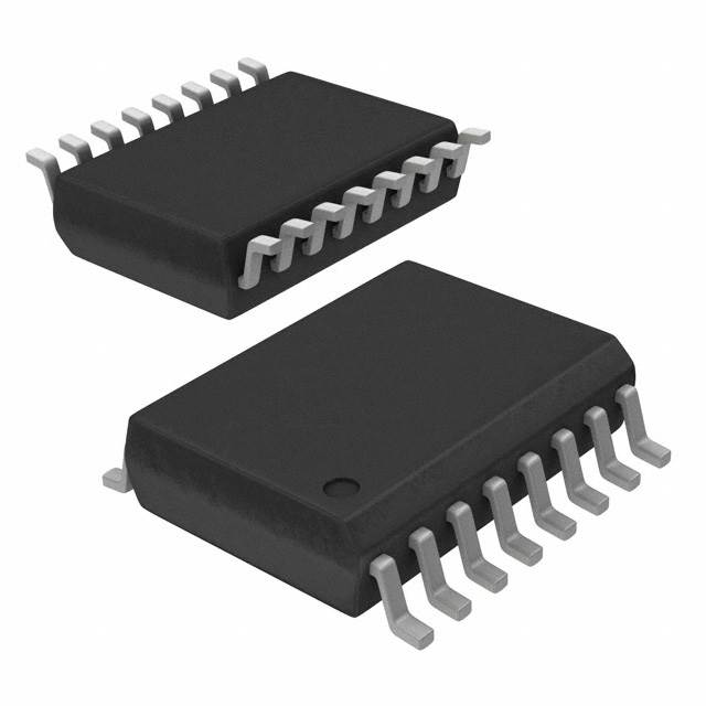
● 16-PIN PLASTIC DIP, SOL-16 PACKAGES
The PGA204 and PGA205 are laser trimmed for very
low offset voltage (50µV), drift (0.25µV/°C) and high
common-mode rejection (115dB at G=1000). They operate with power supplies as low as ±4.5V, allowing use
in battery operated systems. Quiescent current is 5mA.
APPLICATIONS
● DATA ACQUISITION SYSTEM
● GENERAL PURPOSE ANALOG BOARDS
The PGA204 and PGA205 are available in 16-pin
plastic DIP, and SOL-16 surface-mount packages, specified for the –40°C to +85°C temperature range.
● MEDICAL INSTRUMENTATION
VO1
1
–
VIN
4
V+
13
PGA204
PGA205
Over-Voltage
Protection
A1
25kΩ
A1
A0
Digital
Ground
+
VIN
25kΩ
Feedback
12
16
Digitally Selected
Feedback Network
15
A3
11
VO
14
5
A2
Over-Voltage
Protection
25kΩ
6
7
9
VOS Adj
VO2
25kΩ
10
Ref
8
V–
International Airport Industrial Park • Mailing Address: PO Box 11400 • Tucson, AZ 85734 • Street Address: 6730 S. Tucson Blvd. • Tucson, AZ 85706
Tel: (520) 746-1111 • Twx: 910-952-1111 • Cable: BBRCORP • Telex: 066-6491 • FAX: (520) 889-1510 • Immediate Product Info: (800) 548-6132
®
©
SBOS022
1991 Burr-Brown Corporation
PDS-1176A
1
Printed in U.S.A. October, 1993
PGA204/205
�SPECIFICATIONS
ELECTRICAL
PGA204
G=1, 10, 100, 1000V/V
At TA = +25°C, VS = ±15V, and RL = 2kΩ unless otherwise noted.
PGA204BP, BU
PARAMETER
CONDITIONS
INPUT
Offset Voltage, RTI
vs Temperature
vs Power Supply
Long-Term Stability
Impedance, Differential
Common-Mode
Input Common-Mode Range
Safe Input Voltage
Common-Mode Rejection
MIN
TA=+25°C
TA=TMIN to TMAX
VS=±4.5V to ±18V
VO=0V (see text)
VCM=±10V, ∆RS=1kΩ
G=1
G=10
G=100
G=1000
±10.5
TYP
±10+20/G ±50+100/G
±0.1+0.5/G ±0.25+5/G
0.5+2/G
3+10/G
±0.2+0.5/G
1010||6
1010||6
±12.7
±40
80
96
110
115
99
114
123
123
±0.5
±8
±0.5
±8
BIAS CURRENT
vs Temperature
Offset Current
vs Temperature
NOISE, Voltage, RTI(1): f=10Hz
f=100Hz
f=1kHz
fB=0.1Hz to 10Hz
Noise Current
f=10Hz
f=1kHz
fB=0.1Hz to 10Hz
G≥100,
G≥100,
G≥100,
G≥100,
GAIN, Error
OUTPUT
Voltage, Positive(2)
Negative(2)
Load Capacitance Stability
Short Circuit Current
FREQUENCY RESPONSE
Bandwidth, –3dB
Slew Rate
Settling Time(3), 0.1%
0.01%
Overload Recovery
RS=0Ω
RS=0Ω
RS=0Ω
RS=0Ω
IO=5mA, TMIN to TMAX
IO=–5mA, TMIN to TMAX
G=1
G=10
G=100
G=1000
VO=±10V, G=10
G=1
G=10
G=100
G=1000
G=1
G=10
G=100
G=1000
50% Overdrive
DIGITAL LOGIC
Digital Ground Voltage, VDG
Digital Low Voltage
Digital Input Current
Digital High Voltage
POWER SUPPLY, Voltage
Current
TEMPERATURE RANGE
Specification
Operating
θJA
(V+)–1.5
(V–)+1.5
TYP
MAX
UNITS
±125+500/G
±1+10/G
*
*
±25+30/G
±0.25+5/G
*
*
*
*
*
µV
µV/°C
µV/V
µV/mo
Ω || pF
Ω || pF
V
V
*
75
90
106
106
±2
±5
*
nA
pA/°C
nA
pA/°C
nV/√Hz
nV/√ Hz
nV/√Hz
µVp-p
0.4
0.2
18
*
*
*
pA/√Hz
pA/√Hz
pAp-p
±0.024
±0.024
±0.024
±0.05
±10
±0.001
±0.002
±0.002
±0.01
*
*
*
*
*
*
*
*
*
*
*
1
80
10
1
0.7
22
23
100
1000
23
28
140
1300
70
*
(V+)–4
VDG+0.8V
*
*
V+
*
±18
±6.5
*
+85
+125
*
*
1
VDG +2
VIN=0V
dB
dB
dB
dB
*
*
*
*
V–
V–
±4.5
90
106
110
110
*
*
*
*
±2
(V+)–1.3
(V–)+1.3
1000
+23/–17
0.3
MIN
16
13
13
0.4
±0.005
±0.01
±0.01
±0.02
±2.5
±0.0004
±0.0004
±0.0004
±0.0008
G=1
G=10
G=100
G=1000
G=1 to 1000
G=1
G=10
G=100
G=1000
Gain vs Temperature
Nonlinearity
PGA204AP, AU
MAX
±15
+5.2/–4.2
–40
–40
80
±0.05
±0.05
±0.05
±0.1
*
±0.002
±0.004
±0.004
±0.02
%
%
%
%
ppm/°C
% of FSR
% of FSR
% of FSR
% of FSR
*
*
*
*
V
V
pF
mA
*
*
*
*
*
*
*
*
*
*
*
*
*
*
MHz
kHz
kHz
kHz
V/µs
µs
µs
µs
µs
µs
µs
µs
µs
µs
*
*
*
V
V
µA
V
*
±7.5
V
mA
*
*
°C
°C
°C/W
*
*
*
*
* Specification same as PGA204BP.
NOTES: (1) Input-referred noise voltage varies with gain. See typical curves. (2) Output voltage swing is tested for ±10V min on ±11.4V power supplies. (3) Includes
time to switch to a new gain.
®
PGA204/205
2
�SPECIFICATIONS
ELECTRICAL
PGA205
G=1, 2, 4, 8V/V
At TA = +25°C, VS = ±15V, and RL = 2kΩ unless otherwise noted.
PGA205BP, BU
PARAMETER
CONDITIONS
INPUT
Offset Voltage, RTI
vs Temperature
vs Power Supply
Long-Term Stability
Impedance, Differential
Common-Mode
Input Common-Mode Range
Safe Input Voltage
Common-Mode Rejection
MIN
TA=+25°C
TA=TMIN to TMAX
VS=±4.5V to ±18V
VO=0V (see text)
VCM=±10V, ∆RS=1kΩ
G=1
G=2
G=4
G=8
±10.5
TYP
±10+20/G ±50+100/G
±0.1+0.5/G ±0.25+5/G
0.5+2/G
3+10/G
±0.2+0.5/G
1010||6
1010||6
±12.7
±40
80
85
90
95
94
100
106
112
±0.5
±8
±0.5
±8
BIAS CURRENT
vs Temperature
Offset Current
vs Temperature
Noise Voltage, RTI(1): f=10Hz
f=100Hz
f=1kHz
fB=0.1Hz to 10Hz
Noise Current
f=10Hz
f=1kHz
fB=0.1Hz to 10Hz
GAIN, Error
Gain vs Temperature
Nonlinearity
OUTPUT
Voltage, Positive(2)
Negative(2)
Load Capacitance Stability
Short Circuit Current
FREQUENCY RESPONSE
Bandwidth, –3dB
Slew Rate
Settling Time(3), 0.1%
0.01%
Overload Recovery
G=8,
G=8,
G=8,
G=8,
RS=0Ω
RS=0Ω
RS=0Ω
RS=0Ω
IO=5mA, TMIN to TMAX
IO=–5mA, TMIN to TMAX
G=1
G=2
G=4
G=8
VO=±10V, G=8
G=1
G=2
G=4
G=8
G=1
G=2
G=4
G=8
50% overdrive
DIGITAL LOGIC INPUTS
Digital Ground Voltage, VDG
Digital Low Voltage
Digital Low Current
Digital High Voltage
POWER SUPPLY, Voltage
Current
TEMPERATURE RANGE
Specification
Operating
θJA
(V+)–1.5
(V–)+1.5
TYP
MAX
UNITS
±125+500/G
±1+10/G
*
*
±25+30/G
±0.25+5/G
*
*
*
*
*
µV
µV/°C
µV/V
µV/mo
Ω||pF
Ω||pF
V
V
*
75
80
85
89
±2
±5
*
nA
pA/°C
nA
pA/°C
nV/√Hz
nV/√Hz
nV/√Hz
µVp-p
0.4
0.2
18
*
*
*
pA/√Hz
pA/√Hz
pAp-p
±0.024
±0.024
±0.024
±0.024
±10
±0.001
±0.002
±0.002
±0.002
*
*
*
*
*
*
*
*
*
*
*
1
400
200
100
0.7
22
22
23
23
23
23
25
28
70
*
(V+)–4
VDG+0.8V
*
*
V+
*
±18
±6.5
*
+85
+125
*
*
1
VDG+2
VIN=0V
dB
dB
dB
dB
*
*
*
*
V–
V–
±4.5
88
94
100
106
*
*
*
*
±2
(V+)–1.3
(V–)+1.3
1000
+23/–17
0.3
MIN
19
15
15
0.5
±0.005
±0.01
±0.01
±0.01
±2.5
±0.00024
±0.00024
±0.00024
±0.00024
G=1
G=2
G=4
G=8
G=1 to 8
G=1
G=2
G=4
G=8
PGA205AP, AU
MAX
±15
+5.2/–4.2
–40
–40
80
±0.05
±0.05
±0.05
±0.05
*
±0.002
±0.004
±0.004
±0.004
%
%
%
%
ppm/°C
% of FSR
% of FSR
% of FSR
% of FSR
*
*
*
*
V
V
pF
mA
*
*
*
*
*
*
*
*
*
*
*
*
*
*
MHz
kHz
kHz
kHz
V/µs
µs
µs
µs
µs
µs
µs
µs
µs
µs
*
*
*
V
V
µA
V
*
±7.5
V
mA
*
*
°C
°C
°C/W
*
*
*
*
* Specification same as PGA204BP.
NOTES: (1) Input-referred noise voltage varies with gain. See typical curves. (2) Output voltage swing is tested for ±10V min on ±11.4V power supplies. (3) Includes
time to switch to a new gain.
®
3
PGA204/205
�PACKAGE INFORMATION
MODEL
ABSOLUTE MAXIMUM RATINGS
Supply Voltage .................................................................................. ±18V
Analog Input Voltage Range ............................................................. ±40V
Logic Input Voltage Range .................................................................. ±VS
Output Short-Circuit (to ground) .............................................. Continuous
Operating Temperature ................................................. –40°C to +125°C
Storage Temperature ..................................................... –40°C to +125°C
Junction Temperature .................................................................... +150°C
Lead Temperature (soldering –10s) .............................................. +300°C
PACKAGE DRAWING
NUMBER(1)
PACKAGE
PGA204AP
PGA204BP
PGA204AU
PGA204BU
16-Pin Plastic
16-Pin Plastic
SOL-16 Surface
SOL-16 Surface
DIP
DIP
Mount
Mount
180
180
211
211
PGA205AP
PGA205BP
PGA205AU
PGA205BU
16-Pin Plaseic DIP
16-Pin Plastic DIP
SOL-16 Surface Mount
SOL-16 Surface Mount
180
180
211
211
NOTE: (1) For detailed drawing and dimension table, please see end of data
sheet, or Appendix D of Burr-Brown IC Data Book.
ORDERING INFORMATION
MODEL
GAINS
PACKAGE
TEMPERATURE RANGE
PGA204AP
PGA204BP
1, 10, 100, 1000V/V
1, 10, 100, 1000V/V
16-Pin Plastic DIP
16-Pin Plastic DIP
–40 to +85°C
–40 to +85°C
PGA204AU
PGA204BU
1, 10, 100, 1000V/V
1, 10, 100, 1000V/V
SOL-16 Surface-Mount
SOL-16 Surface-Mount
–40 to +85°C
–40 to +85°C
PGA205AP
PGA205BP
1, 2, 4, 8V/V
1, 2, 4, 8V/V
16-Pin Plastic DIP
16-Pin Plastic DIP
–40 to +85°C
–40 to +85°C
PGA205AU
PGA205BU
1, 2, 4, 8V/V
1, 2, 4, 8V/V
SOL-16 Surface-Mount
SOL-16 Surface-Mount
–40 to +85°C
–40 to +85°C
®
PGA204/205
4
�DICE INFORMATION
FPO
PAD
FUNCTION
PAD
FUNCTION
1
2
3
4
5
6
7
8
VO1
—
—
V–IN
V+IN
VOS Adj
VOS Adj
V–
9
10
11
12
13
14
15
16
VO2
Ref
VO
Feedback
V+
Dig. Ground
A0
A1
Substrate Bias: Internally connected to V– power supply.
MECHANICAL INFORMATION
Die Size
Die Thickness
Min. Pad Size
MILS (0.001")
MILLIMETERS
186 x 130 ±5
20 ±3
4x4
4.72 x 3.30 ±0.13
0.51 ±0.08
0.1 x 0.1
Backing
Gold
PGA204/205 DIE TOPOGRAPHY
ELECTROSTATIC
DISCHARGE SENSITIVITY
PIN CONFIGURATION
Top View
VO1
1
16 A1
NC
2
15 A0
NC
3
14 Dig. Ground
V–IN
4
13 V+
V+IN
5
12 Feedback
VOS Adjust
6
11 VO
VOS Adjust
7
10 Ref
V–
8
9
This integrated circuit can be damaged by ESD. Burr-Brown
recommends that all integrated circuits be handled with appropriate precautions. Failure to observe proper handling and
installation procedures can cause damage.
ESD damage can range from subtle performance degradation
to complete device failure. Precision integrated circuits may
be more susceptible to damage because very small parametric
changes could cause the device not to meet its published
specifications.
VO2
NC: No Internal Connection.
®
5
PGA204/205
�TYPICAL PERFORMANCE CURVES
At TA = +25°C, and VS = ±15V, unless otherwise noted.
GAIN vs FREQUENCY
COMMON-MODE REJECTION vs FREQUENCY
140
Common-Mode Rejection (dB)
G = 1k,100
G=1k
Gain (V/V)
1k
G=100
100
G=10
10
G=1
1
G = 10
120
“B” Grade
G=1
100
G = 1k
G = 100
80
G = 10
60
G=1
40
100
Common-Mode Voltage (V)
15
1k
10k
100k
–
VO
+
–
+
VCM
(Any Gain)
A3 + Output
Swing Limit
A3 – Output
Swing Limit
Lim
it
– O ed by
utpu
A
t Sw 2
ing
–10
by A 1 g
in
ited
Lim put Sw
ut
O
–
–5
0
5
10
120
G = 1k
100
G = 100
80
60
G = 10
G=1
40
20
10
100
1k
10k
100k
Output Voltage (V)
Frequency (Hz)
NEGATIVE POWER SUPPLY REJECTION
vs FREQUENCY
INPUT- REFERRED NOISE VOLTAGE
vs FREQUENCY
Input-Referred Noise Voltage (nV/√ Hz)
120
G = 1k
100
G = 100
80
G = 10
60
G=1
40
1M
0
15
140
Power Supply Rejection (dB)
100k
140
Limit
+ Ou ed by A
tput
Swin2
g
VD/2
0
–15
–15
10k
POSITIVE POWER SUPPLY REJECTION
vs FREQUENCY
VD/2
–10
1k
INPUT COMMON-MODE VOLTAGE RANGE
vs OUTPUT VOLTAGE
5
–5
100
Frequency (Hz)
y A1
ed b
Limit ut Swing
p
t
u
+O
10
10
1M
Frequency (Hz)
Power Supply Rejection (dB)
10
20
0
1M
1k
100
G=1
G = 10
10
G = 100, 1k
G = 1k
BW Limit
1
10
100
1k
10k
100k
1M
1
Frequency (Hz)
100
Frequency (Hz)
®
PGA204/205
10
6
1k
10k
�TYPICAL PERFORMANCE CURVES
(CONT)
At TA = +25°C, and VS = ±15V, unless otherwise noted.
INPUT-REFERRED
OFFSET VOLTAGE WARM-UP vs TIME
INPUT BIAS AND INPUT OFFSET CURRENT
vs TEMPERATURE
Input Bias and Input Offset Current (nA)
Offset Voltage Change (µV)
6
4
G > 100
2
0
–2
–4
–6
0
15
30
45
60
75
90
105
120
2
1
±IB
0
IOS
–1
–2
–75
–50
–25
0
25
50
75
100
Time from Power Supply Turn-on (s)
Temperature (°C)
INPUT BIAS CURRENT
vs DIFFERENTIAL INPUT VOLTAGE
INPUT BIAS CURRENT
vs COMMON-MODE INPUT VOLTAGE
3
3
2
2
125
Input Bias Current (mA)
Input Current (mA)
Both Inputs
1
0
–1
G=1
G = 10
–2
–3
–45
–30
One Input
1
0
–15
0
15
30
Over-Voltage
Protection
Normal
Operation
One Input
–3
–45
45
Over-Voltage
Protection
–1
–2
G = 100, 1k
|Ib1| + |Ib2|
Both Inputs
–30
Differential Overload Voltage (V)
MAXIMUM OUTPUT VOLTAGE vs FREQUENCY
–15
0
15
Common-Mode Voltage (V)
30
45
SLEW RATE vs TEMPERATURE
32
1.0
0.8
G ≤ 10
24
Slew Rate (V/µs)
Output Voltage (Vp-p)
28
20
16
12
8
G=8 or 10
0.6
0.4
0.2
4
0
10
100
1k
10k
100k
0
–75
1M
Frequency (Hz)
–50
–25
0
25
50
75
100
125
Temperature (°C)
®
7
PGA204/205
�TYPICAL PERFORMANCE CURVES
(CONT)
At TA = +25°C, and VS = ±15V, unless otherwise noted.
QUIESCENT CURRENT vs TEMPERATURE
OUTPUT CURRENT LIMIT vs TEMPERATURE
6.0
Quiescent Current (mA)
Short Circuit Current (mA)
30
25
+|ICL|
20
–|ICL|
15
10
–40
–15
10
35
60
5.5
5.0
4.5
4.0
–75
85
–50
–25
QUIESCENT CURRENT
vs POWER SUPPLY VOLTAGE
25
50
75
100
125
POSITIVE OUTPUT SWING vs TEMPERATURE
5.2
16
VS = ±15V
14
V+
Output Voltage (V)
5.0
4.5
4.0
12
VS = 11.4
10
8
6
VS = ±4.5
4
V–
2
3.5
±5
0
±10
±15
0
–75
±20
–50
–25
Power Supply Voltage (V)
0
NEGATIVE OUTPUT SWING vs TEMPERATURE
VS = ±15V
–14
–12
VS = 11.4
–10
–8
–6
VS = ±4.5
–4
–2
0
–75
–50
–25
0
25
50
Temperature (°C)
®
PGA204/205
25
50
Temperature (°C)
–16
Output Voltage (V)
Quiescent Current (mA)
0
Temperature (°C)
Temperature (°C)
8
75
100
125
75
100
125
�TYPICAL PERFORMANCE CURVES
(CONT)
At TA = +25°C, and VS = ±15V, unless otherwise noted.
LARGE-SIGNAL RESPONSE, G = 1
SMALL-SIGNAL RESPONSE, G = 1
+200mV
+10V
–200mV
–10V
SMALL-SIGNAL RESPONSE, G = 10
LARGE-SIGNAL RESPONSE, G = 10
+200mV
+10V
–200mV
–10V
SMALL-SIGNAL RESPONSE, G = 1000
LARGE-SIGNAL RESPONSE, G = 1000
+200mV
+10V
–200mV
–10V
®
9
PGA204/205
�TYPICAL PERFORMANCE CURVES
(CONT)
At TA = +25°C, and VS = ±15V, unless otherwise noted.
INPUT-REFERRED NOISE,
0.1 TO 10Hz, G = 1000
NOISE, 0.1 TO 10Hz, G = 1
0.5µV/Div
0.2µV/Div
1s/Div
1s/Div
APPLICATION INFORMATION
be used to sense the output voltage directly at the load for
best accuracy.
Figure 1 shows the basic connections required for operation
of the PGA204/205. Applications with noisy or high impedance power supplies may require decoupling capacitors
close to the device pins as shown.
The output is referred to the output reference (Ref) terminal
which is normally grounded. This must be a low-impedance
connection to assure good common-mode rejection. A resistance of 5Ω in series with the Ref pin will cause a typical
device to degrade to approximately 80dB CMR (G=1).
DIGITAL INPUTS
The digital inputs A0 and A1 select the gain according to the
logic table in Figure 1. Logic “1” is defined as a voltage
greater than 2V above digital ground potential (pin 14).
Digital ground can be connected to any potential from the
V– power supply to 4V less than V+. Digital ground is
normally connected to ground. The digital inputs interface
directly CMOS and TTL logic components.
The PGA204/205 has an output feedback connection (pin
12). Pin 12 must be connected to the output terminal (pin 11)
for proper operation. The output Feedback connection can
Approximately 1µA flows out of the digital input pins when
a logic “0” is applied. Logic input current is nearly zero with
a logic “1” input. A constant current of approximately
+15V
1µF
VO1
1
–
VIN
4
PGA204
PGA205
Over-Voltage
Protection
Feedback
A1
25kΩ
12
25kΩ
16
Digitally Selected
Feedback Network
15
A3
11
VO
14
+
–
VO = G (VIN
– VIN
)
+
VIN
5
25kΩ
6
PGA204 PGA205
1
2
4
8
1
10
100
1000
7
VOS
Adj
GAIN
Ref
A2
Over-Voltage
Protection
9
8
–
VIN
0
1
0
1
+15V
PGA204
+
VIN
A1 A0
FIGURE 1. Basic Connections.
®
PGA204/205
Sometimes shown in simplified form:
1µF
VO2
A 1 A0
0
0
1
1
10
25kΩ
10
VO
�Some applications select gain of the PGA204/205 with
switches or jumpers. Figure 2 shows pull-up resistors connected to assure a noise-free logic “1” when the switch,
jumper or open-collector logic is open or off. Fixed-gain
applications can connect the logic inputs directly to V+ or
V– (or other valid logic level); no resistor is required.
V+
4
–
VIN
100kΩ
Over-Voltage
Protection
A1
100kΩ
16
Digitally Selected
Feedback Network
15
OFFSET VOLTAGE
Voltage offset of the PGA204/205 consists of two components—input stage offset and output stage offset. Both
components are specified in the specification table in equation form:
14
+
VIN
5
Switches, jumpers
or open-collector
logic output.
A2
Over-Voltage
Protection
6
Digital ground can
alternatively be connected
to V– power supply.
7
9
VOS = VOSI + VOSO / G
VO2
VOS
Adj
where:
VOS total is the combined offset, referred to the input.
FIGURE 2. Switch or Jumper-Selected Digital Inputs.
VOSI is the offset voltage of the input stage, A1 and A2.
VOSO is the offset voltage of the output difference
amplifier, A3.
1.3mA flows in the digital ground pin. It is good practice to
return digital ground through a separate connection path so
that analog ground is not affected by the digital ground
current.
VOSI and VOSO do not change with gain. The composite
offset voltage VOS changes with gain because of the gain
term in equation 1. Input stage offset dominates in high gain
(G≥100); both sources of offset may contribute at low gain
(G=1 to 10).
The digital inputs, A0 and A1, are not latched; a change in
logic inputs immediately selects a new gain. Switching time
of the logic is approximately 1µs. The time to respond to
gain change is effectively the time it takes the amplifier to
settle to a new output voltage in the newly selected gain (see
settling time specifications).
OFFSET TRIMMING
Both the input and output stages are laser trimmed for very
low offset voltage and drift. Many applications require no
external offset adjustment.
Many applications use an external logic latch to access gain
control data from a high speed data bus (see Figure 7). Using
an external latch isolates the high speed digital bus from
sensitive analog circuitry. Locate the latch circuitry as far as
practical from analog circuitry.
VO1
4
13
PGA204
PGA205
Over-Voltage
Protection
A1
25kΩ
A1
A0
Digital
Ground
+
VIN
Figure 3 shows an optional input offset voltage trim circuit.
This circuit should be used to adjust only the input stage
offset voltage of the PGA204/205. Do this by programming
V+
1
–
VIN
25kΩ
Feedback
12
Resistors can be substituted
for REF200. Power supply
rejection will be degraded.
16
Digitally Selected
Feedback Network
15
A3
11
14
5
25kΩ
7
6
9
VO2
Input Offset
Adjustment
Trim Range
≈ ±250µV
+
–
VO = G (VIN
– VIN
) + VREF
V+
100µA
1/2 REF200
VREF
A2
Over-Voltage
Protection
(1)
25kΩ
10
100Ω
OPA177
8
10kΩ
±10mV
Adjustment Range
V–
200kΩ
to 1MΩ
100Ω
Output Offset
Adjustment
100µA
1/2 REF200
V+
V–
FIGURE 3. Optional Offset Voltage Trim Circuit.
®
11
PGA204/205
�it to its highest gain and trimming the output voltage to zero
with the inputs grounded. Drift performance usually improves slightly when the input offset is nulled with this
procedure.
Microphone,
Hydrophone
etc.
Do not use the input offset adjustment to trim system offset
or offset produced by a sensor. Nulling offset that is not
produced by the input amplifiers will increase temperature
drift by approximately 3.3µV/°C per 1mV of offset adjustment.
Many applications that need input stage offset adjustment do
not need output stage offset adjustment. Figure 3 also shows
a circuit for adjusting output offset voltage. First, adjust the
input offset voltage as discussed above. Then program the
device for G=1 and adjust the output to zero. Because of the
interaction of these two adjustments at G=8, the PGA205
may require iterative adjustment.
47kΩ
47kΩ
Thermocouple
PGA204
10kΩ
The output offset adjustment can be used to trim sensor or
system offsets without affecting drift. The voltage applied to
the Ref terminal is summed with the output signal. Low
impedance must be maintained at this node to assure good
common-mode rejection. This is achieved by buffering the
trim voltage with an op amp as shown.
PGA204
VR
NOISE PERFORMANCE
The PGA204/205 provides very low noise in most applications. Low frequency noise is approximately 0.4µVp-p measured from 0.1 to 10Hz. This is approximately one-tenth the
noise of “low noise” chopper-stabilized amplifiers.
Center-tap provides
bias current return.
Bridge
PGA204
Bias current return
inherrently provided by source.
INPUT BIAS CURRENT RETURN PATH
The input impedance of the PGA204/205 is extremely high—
approximately 1010Ω. However, a path must be provided for
the input bias current of both inputs. This input bias current
is typically less than ±1nA (it can be either polarity due to
cancellation circuitry). High input impedance means that
this input bias current changes very little with varying input
voltage.
FIGURE 4. Providing an Input Common-Mode Current
Path.
INPUT COMMON-MODE RANGE
The linear common-mode range of the input op amps of the
PGA204/205 is approximately ±12.7V (or 2.3V from the
power supplies). As the output voltage increases, however,
the linear input range will be limited by the output voltage
swing of the input amplifiers, A1 and A2. The commonmode range is related to the output voltage of the complete
amplifier—see performance curve “Input Common-Mode
Range vs Output Voltage”.
Input circuitry must provide a path for this input bias current
if the PGA204/205 is to operate properly. Figure 4 shows
provisions for an input bias current path. Without a bias
current return path, the inputs will float to a potential which
exceeds the common-mode range of the PGA204/205 and
the input amplifiers will saturate. If the differential source
resistance is low, bias current return path can be connected
to one input (see thermocouple example in Figure 4). With
higher source impedance, using two resistors provides a
balanced input with possible advantages of lower input
offset voltage due bias current and better common-mode
rejection.
A combination of common-mode and differential input
voltage can cause the output of A1 or A2 to saturate. Figure
5 shows the output voltage swing of A1 and A2 expressed in
terms of a common-mode and differential input voltages.
Output swing capability of these internal amplifiers is the
same as the output amplifier, A3. For applications where
input common-mode range must be maximized, limit the
output voltage swing by selecting a lower gain of the
PGA204/205 (see performance curve “Input Common-Mode
Voltage Range vs Output Voltage”). If necessary, add gain
after the PGA204/205 to increase the voltage swing.
Many sources or sensors inherently provide a path for input
bias current (e.g. the bridge sensor shown in Figure 4).
These applications do not require additional resistor(s) for
proper operation.
®
PGA204/205
PGA204
12
�VCM –
4
G • VD
2
VO1
V+
1
13
PGA204
PGA205
Over-Voltage
Protection
A1
25kΩ
Feedback
12
25kΩ
VD
2
A1
A0
VD
2
VCM
Digital
Ground
16
Digitally Selected
Feedback Network
15
A3
VO
11
14
5
A2
Over-Voltage
Protection
25kΩ
9
VCM +
G • VD
2
Ref
10
25kΩ
8
VO2
V–
FIGURE 5. Voltage Swing of A1 and A2.
Input-overload often produces an output voltage that appears
normal. For example, consider an input voltage of +20V on
one input and +40V on the other input will obviously exceed
the linear common-mode range of both input amplifiers.
Since both input amplifiers are saturated to the nearly the
same output voltage limit, the difference voltage measured
by the output amplifier will be near zero. The output of the
PGA204/205 will be near 0V even though both inputs are
overloaded.
V+
47kΩ
47kΩ
–
VIN
A1
A0
PGA204
PGA205
+
VIN
INPUT PROTECTION
The inputs of the PGA204/205 are individually protected for
voltages up to ±40V. For example, a condition of –40V on
one input and +40V on the other input will not cause
damage. Internal circuitry on each input provides low series
impedance under normal signal conditions. To provide
equivalent protection, series input resistors would contribute
excessive noise. If the input is overloaded, the protection
circuitry limits the input current to a safe value (approximately 1.5mA). The typical performance curve “Input Bias
Current vs Common-Mode Input Voltage” shows this input
current limit behavior. The inputs are protected even if no
power supply voltage is present.
B
C
X
D
A
D1, D2: IN4148, IN914, etc.
GAIN
SWITCH
POSITION
PGA204
PGA205
A
B
C
D
1
10
100
1000
1
2
4
8
FIGURE 6. Switch-Selected PGIA.
The information provided herein is believed to be reliable; however, BURR-BROWN assumes no responsibility for inaccuracies or omissions. BURR-BROWN assumes
no responsibility for the use of this information, and all use of such information shall be entirely at the user’s own risk. Prices and specifications are subject to change
without notice. No patent rights or licenses to any of the circuits described herein are implied or granted to any third party. BURR-BROWN does not authorize or warrant
any BURR-BROWN product for use in life support devices and/or systems.
®
13
PGA204/205
�+15V
14
VO1
2
1
HI-509
4
4
5
13
PGA204
PGA205
Over-Voltage
Protection
A1
8
–
V+
25kΩ
VIN
25kΩ
Feedback
12
6
7
13
A1
16
A0
15
Digitally Selected
Feedback Network
A3
VO
11
14
12
9
+
VIN
11
5
10
A0
3 15
1
A2
Over-Voltage
Protection
25kΩ
7
6
A1
16
9
VO2
VOS
Adj
25kΩ
Ref
10
8
V–
–15V
Data Out
74HC574
Data In
To Address
Decoding Logic
CK
Data Bus
FIGURE 7. Multiplexed-Input Programmable Gain IA.
A0 A1
VO1
–
VIN
PGA204
PGA205
+
VIN
VO
Ref
VO2
A1 A0
220Ω
20kΩ
20kΩ
OPA177
FIGURE 8. Shield Drive Circuit.
+
VIN
A1
A1
AO PGA205
AO PGA205
VO
–
–
VIN
VO
PGA204
PGA205
VIN
+
Ref
C1
0.1µF
R1
1MΩ
A1 A0
GAIN
A3
A2
A1
A0
1
2
4
8
16
32
64
0
0
1
1
1
1
1
0
1
0
1
1
1
1
0
0
0
0
0
1
1
0
0
0
0
1
0
1
OPA602
1
2πR1C1
= 1.59Hz
FIGURE 9. Binary Gain Steps, G=1 to G=64.
FIGURE 10. AC-Coupled PGIA.
®
PGA204/205
f–3dB =
14
�PACKAGE OPTION ADDENDUM
www.ti.com
14-Oct-2022
PACKAGING INFORMATION
Orderable Device
Status
(1)
Package Type Package Pins Package
Drawing
Qty
Eco Plan
(2)
Lead finish/
Ball material
MSL Peak Temp
Op Temp (°C)
Device Marking
(3)
Samples
(4/5)
(6)
PGA204AP
ACTIVE
PDIP
N
16
25
RoHS & Green
Call TI
N / A for Pkg Type
PGA204AP
Samples
PGA204AU
ACTIVE
SOIC
DW
16
40
RoHS & Green
NIPDAU
Level-3-260C-168 HR
-40 to 85
PGA204AU
Samples
PGA204AU/1K
ACTIVE
SOIC
DW
16
1000
RoHS & Green
Call TI
Level-3-260C-168 HR
-40 to 85
PGA204AU
Samples
PGA204AU/1KE4
ACTIVE
SOIC
DW
16
1000
RoHS & Green
Call TI
Level-3-260C-168 HR
-40 to 85
PGA204AU
Samples
PGA204AUE4
ACTIVE
SOIC
DW
16
40
RoHS & Green
NIPDAU
Level-3-260C-168 HR
-40 to 85
PGA204AU
Samples
PGA204BP
ACTIVE
PDIP
N
16
25
RoHS & Green
Call TI
N / A for Pkg Type
PGA204BP
Samples
PGA204BU
ACTIVE
SOIC
DW
16
40
RoHS & Green
Call TI
Level-3-260C-168 HR
PGA204BU
Samples
PGA204BU/1K
ACTIVE
SOIC
DW
16
1000
RoHS & Green
Call TI
Level-3-260C-168 HR
PGA204BU
Samples
PGA205AP
ACTIVE
PDIP
N
16
25
RoHS & Green
Call TI
N / A for Pkg Type
-40 to 85
PGA205AP
Samples
PGA205AU
ACTIVE
SOIC
DW
16
40
RoHS & Green
Call TI
Level-3-260C-168 HR
-40 to 85
PGA205AU
Samples
PGA205AU/1K
ACTIVE
SOIC
DW
16
1000
RoHS & Green
Call TI
Level-3-260C-168 HR
-40 to 85
PGA205AU
Samples
PGA205BP
ACTIVE
PDIP
N
16
25
RoHS & Green
Call TI
N / A for Pkg Type
-40 to 85
PGA205BP
Samples
PGA205BU
ACTIVE
SOIC
DW
16
40
RoHS & Green
Call TI
Level-3-260C-168 HR
-40 to 85
PGA205BU
Samples
PGA205BUG4
ACTIVE
SOIC
DW
16
40
RoHS & Green
Call TI
Level-3-260C-168 HR
-40 to 85
PGA205BU
Samples
(1)
The marketing status values are defined as follows:
ACTIVE: Product device recommended for new designs.
LIFEBUY: TI has announced that the device will be discontinued, and a lifetime-buy period is in effect.
NRND: Not recommended for new designs. Device is in production to support existing customers, but TI does not recommend using this part in a new design.
PREVIEW: Device has been announced but is not in production. Samples may or may not be available.
OBSOLETE: TI has discontinued the production of the device.
(2)
RoHS: TI defines "RoHS" to mean semiconductor products that are compliant with the current EU RoHS requirements for all 10 RoHS substances, including the requirement that RoHS substance
do not exceed 0.1% by weight in homogeneous materials. Where designed to be soldered at high temperatures, "RoHS" products are suitable for use in specified lead-free processes. TI may
reference these types of products as "Pb-Free".
Addendum-Page 1
�PACKAGE OPTION ADDENDUM
www.ti.com
14-Oct-2022
RoHS Exempt: TI defines "RoHS Exempt" to mean products that contain lead but are compliant with EU RoHS pursuant to a specific EU RoHS exemption.
Green: TI defines "Green" to mean the content of Chlorine (Cl) and Bromine (Br) based flame retardants meet JS709B low halogen requirements of