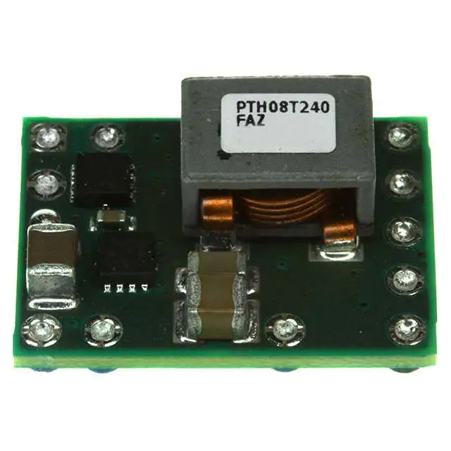
PTH08T240F
www.ti.com ............................................................................................................................................... SLTS277D – DECEMBER 2006 – REVISED MARCH 2009
10-A, 4.5-V to 14-V INPUT, NON-ISOLATED POWER MODULE
FOR 3-GHz DSP SYSTEMS
FEATURES
1
•
•
•
•
•
•
2
•
•
•
•
•
•
•
•
•
Up to 10-A Output Current
4.5-V to 14-V Input Voltage
Wide-Output Voltage Adjust (0.69 V to 2.0 V)
±1.5% Total Output Voltage Variation
Efficiencies up to 93%
Output Overcurrent Protection
(Nonlatching, Auto-Reset)
Operating Temperature: –40°C to 85°C
Safety Agency Approvals:
– UL/IEC/CSA-C22.2 60950-1
Prebias Startup
On/Off Inhibit
Differential Output Voltage Remote Sense
Adjustable Undervoltage Lockout
Auto-Track™ Sequencing
SmartSync Technology
POLA™ Compatible
•
•
•
TurboTrans™ Technology
Designed to meet Ultra-Fast Transient
Requirements for 3-GHz DSP Systems
15 mV Output Voltage Deviation
(CO = 2000 µF, ΔI = 3 A)
APPLICATIONS
•
Wireless Infrastructure Base Stations
DESCRIPTION
The PTH08T240F is a high-performance 10-A rated, non-isolated power module designed to meet ultra-fast
transient requirements for 3-GHz DSP systems like Texas Instrument's TMS320TCI6488. This module is an
addition to the 2nd generation of the popular PTH series power modules which include a reduced footprint and
additional features.
Operating from an input voltage range of 4.5 V to 14 V, the PTH08T240F requires a single resistor to set the
output voltage to any value over the range, 0.69 V to 2.0 V. The output voltage range makes the PTH08T240F
particularly suitable for the 3-GHz DSP's core voltage requirements.
The module incorporates a comprehensive list of features. Output over-current and over-temperature shutdown
protects against most load faults. A differential remote sense ensures tight load regulation. An adjustable
under-voltage lockout allows the turn-on voltage threshold to be customized. Auto-Track™sequencing is a
popular feature that greatly simplifies the simultaneous power-up and power-down of multiple modules in a
power system.
1
2
Please be aware that an important notice concerning availability, standard warranty, and use in critical applications of Texas
Instruments semiconductor products and disclaimers thereto appears at the end of this data sheet.
Auto-Track, TurboTrans, TMS320 are trademarks of Texas Instruments.
PRODUCTION DATA information is current as of publication date.
Products conform to specifications per the terms of the Texas
Instruments standard warranty. Production processing does not
necessarily include testing of all parameters.
Copyright © 2006–2009, Texas Instruments Incorporated
�PTH08T240F
SLTS277D – DECEMBER 2006 – REVISED MARCH 2009 ............................................................................................................................................... www.ti.com
The PTH08T240F includes new patented technologies, TurboTrans™ and SmartSync. The TurboTrans feature
optimizes the transient response of the regulator while simultaneously reducing the quantity of external output
capacitors required to meet a target voltage deviation specification. TurboTrans allows PTH08T240F to meet the
tight transient voltage tolerances required by 3-GHz DSPs with minimal output capacitance. SmartSync allows for
switching frequency synchronization of multiple modules, thus simplifying EMI noise suppression tasks and
reducing input capacitor RMS current requirements. The module uses double-sided surface mount construction
to provide a low profile and compact footprint. Package options include both through-hole and surface mount
configurations that are lead (Pb) - free and RoHS compatible.
2
Submit Documentation Feedback
Copyright © 2006–2009, Texas Instruments Incorporated
Product Folder Link(s): PTH08T240F
�PTH08T240F
www.ti.com ............................................................................................................................................... SLTS277D – DECEMBER 2006 – REVISED MARCH 2009
These devices have limited built-in ESD protection. The leads should be shorted together or the device placed in conductive foam
during storage or handling to prevent electrostatic damage to the MOS gates.
SmartSync
TurboTrans
Track
1
10
VI
Track
2
SYNC
TT
+Sense
VI
11 INH/UVLO
GND
+
RUVLO
1%
0.05 W
(Optional)
3
CI
220 mF
(Required)
CI 2
22 mF
(Recommended)
4
VO
7
VOAdj
8
+Sense
VO
-Sense
GND
6
5
PTH08T240F
Inhibit
RTT
1%
0.05W
(Required)
9
[A]
RSET
1%
0.05 W
(Required)
GND
+
L
O
A
D
CO
1000 mF
(Required)
-Sense
GND
UDG-07125
A.
RSET required to set the output voltage to a value higher than 0.69 V. See Electrical Characteristics table.
Submit Documentation Feedback
Copyright © 2006–2009, Texas Instruments Incorporated
Product Folder Link(s): PTH08T240F
3
�PTH08T240F
SLTS277D – DECEMBER 2006 – REVISED MARCH 2009 ............................................................................................................................................... www.ti.com
ORDERING INFORMATION
For the most current package and ordering information, see the Package Option Addendum at the end of this datasheet, or see
the TI website at www.ti.com.
DATASHEET TABLE OF CONTENTS
DATASHEET SECTION
PAGE NUMBER
ENVIRONMENTAL AND ABSOLUTE MAXIMUM RATINGS
3
ELECTRICAL CHARACTERISTICS TABLE
4
TERMINAL FUNCTIONS
5
TYPICAL CHARACTERISTICS (VI = 5V)
6
TYPICAL CHARACTERISTICS (VI = 8V)
7
TYPICAL CHARACTERISTICS (VI = 12V)
8
ADJUSTING THE OUTPUT VOLTAGE
9
INPUT & OUTPUT CAPACITOR RECOMMENDATIONS
11
TURBOTRANS™ INFORMATION
15
UNDERVOLTAGE LOCKOUT (UVLO)
21
SOFT-START POWER-UP
22
OUTPUT INHIBIT
23
OVER-CURRENT PROTECTION
24
OVER-TEMPERATURE PROTECTION
24
REMOTE SENSE
24
SYCHRONIZATION (SMARTSYNC)
25
AUTO-TRACK SEQUENCING
26
PREBIAS START-UP
29
TAPE & REEL AND TRAY DRAWINGS
31
ENVIRONMENTAL AND ABSOLUTE MAXIMUM RATINGS
(Voltages are with respect to GND)
UNIT
VTrack
Track pin voltage
TA
Operating temperature range Over VI range
Twave
Wave soldering temperature
Surface temperature of module body or
pins
(5 seconds maximum)
Treflow
Solder reflow temperature
Surface temperature of module body or
pins
Tstg
Storage temperature
Storage temperature of module removed from shipping package
Tpkg
Packaging temperature
Shipping Tray or Tape and Reel storage or bake temperature
45
Mechanical shock
Per Mil-STD-883D, Method 2002.3 1
msec, 1/2 sine, mounted
suffix AD
500
suffix AS & AZ
250
Mechanical vibration
–0.3 to VI + 0.3
Mil-STD-883D, Method 2007.2 20-2000 Hz
Weight
Flammability
(1)
4
V
–40 to 85
suffix AD
260
suffix AS
235 (1)
suffix AZ
(1)
260
°C
–55 to 125
G
15
5
grams
Meets UL94V-O
During reflow of surface mount package version do not elevate peak temperature of the module, pins or internal components above the
stated maximum.
Submit Documentation Feedback
Copyright © 2006–2009, Texas Instruments Incorporated
Product Folder Link(s): PTH08T240F
�PTH08T240F
www.ti.com ............................................................................................................................................... SLTS277D – DECEMBER 2006 – REVISED MARCH 2009
ELECTRICAL CHARACTERISTICS
PTH08T240F
TA = 25°C, VI = 5 V, VO = 1.0 V, CI = 220 µF, CO = 1000 µF, and IO = IO max (unless otherwise stated)
PARAMETER
TEST CONDITIONS
PTH08T240F
MIN
IO
Output current
Over VO range
VI
Input voltage range
Over IO range
VOADJ
Output voltage adjust range
Over IO range
25°C, natural convection
η
4.5
1.3V ≤ VO ≤ 2.0
4.5
±0.3
%VO
±3
mV
Load regulation
Over IO range
±2
Total output variation
Includes set-point, line, load, –40°C ≤ TA ≤ 85°C
IO = 10 A
90%
RSET = 7.09 kΩ, VO = 1.5 V
88%
RSET = 12.1 kΩ, VO = 1.2 V
87%
VO Ripple (peak-to-peak)
20-MHz bandwidth
Overcurrent threshold
Reset, followed by auto-recovery
Transient response
CO = 1000 µF, Type C
2.5 A/µs load step RTT=open
0.5 A to 3.5 A step
VO = 0.9 V
CO = 2000 µF, Type C
RTT=24.3=kΩ
Pin to GND
Track slew rate capability
CO ≤ CO (max)
UVLOADJ
VI increasing, RUVLO = OPEN
Adjustable Under-voltage lockout
VI decreasing, RUVLO = OPEN
(pin 11)
Hysteresis, RUVLO ≤ 52.3 kΩ
(1)
A
500
µs
VO over/undershoot
25
mV
Recovery time
800
µs
VO over/undershoot
14
mV
Recovery time
1
4.3
3.7
fs
Switching frequency
Over VI and IO ranges, SmartSync (pin 1) to GND
fSYNC
Synchronization frequency
VSYNCH
SYNC High-Level Input Voltage
VSYNCL
SYNC Low-Level Input Voltage
tSYNC
SYNC Minimum Pulse Width
CI
External input capacitance
Reliability
(4)
(5)
(6)
4.45
4.2
V
Open (4)
-0.2
Input low current (IIL), Pin 11 to GND
Inhibit (pin 11) to GND, Track (pin 10) open
260
0.8
µA
5
mA
340
kHz
240
300
400
kHz
2
5.5
V
200
Nonceramic
Telcordia SR-332, 50% stress, TA= 40°C, ground benign
Nonceramic
V
nSec
220
(5)
1000
(6)
10000
µF
1000
10000
µF×mΩ
Ceramic
Capacitance × ESR product (CO × ESR)
V
-235
0.8
Capacitance Value
µA
V/ms
0.5
Input low voltage (VIL)
Input standby current
MTBF
mVPP
20
Iin
External output capacitance
%VO
85%
10
Input high voltage (VIH)
CO
(2)
–130 (3)
Track input current (pin 10)
Inhibit control (pin 11)
mV
±1.5
RSET = 4.78 kΩ, VO = 1.8 V
dVtrack/dt
(3)
V
%VO
Over VI range
IIL
(2)
(2)
–40°C < TA < 85°C
ΔVtrTT
(1)
±1
V
Line regulaltion
ttr
ttrTT
2.0
±0.5
A
(1)
14
0.69
RSET = 20.8 kΩ, VO = 1.0 V
ΔVtr
10
14
Temperature variation
Efficiency
ILIM
UNIT
MAX
0
0.69V ≤ VO < 1.3V
Set-point voltage tolerance
VO
TYP
22
µF
(5)
6.1
106 Hr
For output voltages less than 1.3 V, the ripple may increase (up to 2×) when operating at input voltages greater than (VO × 11). See the
SmartSync section and the TurboTrans section of the datasheet for additional information.
The set-point voltage tolerance is affected by the tolerance and stability of RSET. The stated limit is unconditionally met if RSET has a
tolerance of 1% with 100 ppm/°C or better temperature stability.
A low-leakage (