SN65DSI86
SN65DSI86
SLLSEH2C – SEPTEMBER 2013 – REVISED OCTOBER
2020
SLLSEH2C – SEPTEMBER 2013 – REVISED OCTOBER 2020
www.ti.com
SN65DSI86 MIPI® DSI to eDP™ Bridge
1 Features
•
•
•
•
•
•
•
•
•
•
•
•
•
•
•
3 Description
Embedded DisplayPort™ ( eDP™) 1.4 compliant
supporting 1, 2, or 4 lanes at 1.62 Gbps (RBR),
2.16 Gbps, 2.43 Gbps, 2.7 Gbps (HBR), 3.24
Gbps, 4.32 Gbps, or 5.4 Gbps (HBR2).
Implements MIPI® D-PHY version 1.1 physical
layer front-end and display serial interface (DSI)
version 1.02.00
Dual-channel DSI receiver configurable for one,
two, three, or four D-PHY data lanes per channel
operating up to 1.5 Gbps per lane
Supports 18 bpp and 24 bpp DSI video packets
with RGB666 and RGB888 formats
Suitable for 60 fps 4K 4096 × 2304 resolution at 18
bpp color, and WUXGA 1920 × 1200 resolution
with 3D graphics at 60 fps (120 fps equivalent)
MIPI front-end configurable for single-channel or
dual-channel DSI configuration
Supports dual-channel DSI odd, even and left,
right operating modes
1.2-V main VCC power supply and 1.8-V supply
for digital I/Os
Low-power features include panel refresh and
MIPI ultralow power state (ULPS) support
DisplayPort lane polarity and assignment
configurable.
Supports 12-MHz, 19.2-MHz, 26-MHz, 27-MHz,
and 38.4-MHz frequencies through external
reference clock (REFCLK)
ESD rating ±4 kV (HBM)
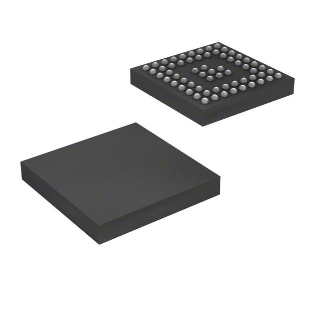
Packaged in 64ball 5-mm x 5-mm nFBGA (ZXH)
I2C configurable
Temperature range: –40°C to +85°C
The SN65DSI86 DSI to embedded DisplayPort (eDP)
bridge features a dual-channel MIPI D-PHY receiver
front-end configuration with four lanes per channel
operating at 1.5 Gbps per lane and a maximum input
bandwidth of 12 Gbps. The bridge decodes MIPI DSI
18-bpp RGB666 and 24-bpp RGB888 packets and
converts the formatted video data stream to a
DisplayPort with up to four lanes at either 1.62 Gbps,
2.16 Gbps, 2.43 Gbps, 2.7 Gbps, 3.24 Gbps, 4.32
Gbps, or 5.4 Gbps.
The SN65DSI86 is well suited for WQXGA at 60
frames per second, as well as 3D graphics at 4K and
true HD (1920 × 1080) resolutions at an equivalent
120 fps with up to 24 bpp. Partial line buffering is
implemented to accommodate the data stream
mismatch between the DSI and DisplayPort
interfaces.
Device Information(1)
PART NUMBER
SN65DSI86
BODY SIZE (NOM)
nFBGA (64)
5.00 mm × 5.00 mm
Panel
DA[3/0]P/N
DP_ML[0:3]P
DACP/N
Application DB[3/0]P/N
Processor
With DSI
DBCP/N
Output
SCL/SDA
Dual- Channel
DSI toeDP
Bridge
SN65DSI86
DP_ML[0:3]M
AUXP/N
HPD
IRQ
Copyright © 2017, Texas Instruments Incorporated
LCD eDP TCON
2 Applications
•
•
•
•
•
PACKAGE
Simple Diagram
PC & notebooks
Tablets
Retail automation & payment
Test and measurement
Factory automation and control
An IMPORTANT NOTICE at the end of this data sheet addresses availability, warranty, changes, use in safety-critical applications,
Submit Document Feedback
Copyright
© 2020 Texas
Instruments
Incorporated
intellectual
property
matters
and other important disclaimers. PRODUCTION DATA.
Product Folder Links: SN65DSI86
1
�SN65DSI86
www.ti.com
SLLSEH2C – SEPTEMBER 2013 – REVISED OCTOBER 2020
Table of Contents
1 Features............................................................................1
2 Applications..................................................................... 1
3 Description.......................................................................1
4 Revision History.............................................................. 2
5 Description (continued).................................................. 4
6 Pin Configuration and Functions...................................5
7 Specifications.................................................................. 8
7.1 Absolute Maximum Ratings........................................ 8
7.2 ESD Ratings............................................................... 8
7.3 Recommended Operating Conditions.........................8
7.4 Thermal Information....................................................8
7.5 Electrical Characteristics...........................................10
7.6 Timing Requirements................................................ 12
7.7 Switching Characteristics..........................................13
8 Detailed Description......................................................17
8.1 Overview................................................................... 17
8.2 Functional Block Diagram......................................... 17
8.3 Feature Description...................................................17
8.4 Device Functional Modes..........................................21
8.5 Programming............................................................ 43
8.6 Register Map.............................................................44
9 Application and Implementation.................................. 67
9.1 Application Information............................................. 67
9.2 Typical Application.................................................... 68
10 Power Supply Recommendations..............................73
10.1 VCC Power Supply.................................................. 73
10.2 VCCA Power supply................................................. 73
10.3 VPLL and VCCIO Power Supplies..............................73
11 Layout........................................................................... 74
11.1 Layout Guidelines................................................... 74
11.2 Layout Example...................................................... 75
12 Device and Documentation Support..........................76
12.1 Documentation Support.......................................... 76
12.2 Receiving Notification of Documentation Updates..76
12.3 Community Resources............................................76
12.4 Trademarks............................................................. 76
13 Mechanical, Packaging, and Orderable
Information.................................................................... 76
4 Revision History
NOTE: Page numbers for previous revisions may differ from page numbers in the current version.
Changes from Revision B (March 2017) to Revision C (October 2020)
Page
• NOTE: The device in the MicroStar Jr. BGA packaging were redesigned using a laminate nFBGA package.
This nFBGA package offers datasheet-equivalent electrical performance. It is also footprint equivalent to the
MicroStar Jr. BGA. The new package designator in place of the discontinued package designator will be
updated throughout the datasheet......................................................................................................................1
• Changed u*jr ZQE to nFBGA ZXH..................................................................................................................... 1
• Changed u*jr ZQE to nFBGA ZXH..................................................................................................................... 5
• Changed u*jr ZQE to nFBGA ZXH. Updated thermal information...................................................................... 8
Changes from Revision A (November 2015) to Revision B (March 2017)
Page
• Deleted device number SN65DSI96 from the data sheet...................................................................................1
• Deleted Feature "Adaptive Content Management and Backlight PWM Control...".............................................1
• Added Feature: I2C Configurable....................................................................................................................... 1
• Updated the Applications list.............................................................................................................................. 1
• Replaced the Simple Diagram............................................................................................................................ 1
• Changed SN65DSIx6 To: SN65DSI86 throughout the data sheet......................................................................4
• Deleted pagraph "For the SN65DSI96, the brightness is controlled.." from the Pulse Width Modulation (PWM)
section.............................................................................................................................................................. 19
• Deleted the PWM Backlight Selection Options table ....................................................................................... 19
• Deleted the Assertive Display (SN65DSI96 Only) section................................................................................21
• Deleted step: "Configure Assertive Display Core. (For SN65DSI96 only)" from the Power-Up Sequence
section.............................................................................................................................................................. 21
• Deleted step: "For SN65DSI96, disable Assertive Display core by clearing the ADEN bit." from the Power
Down Sequence section................................................................................................................................... 22
• Changed Figure 8-14 .......................................................................................................................................44
• Deleted SN65DSI96 from address 0x00 through 0x07 of Table 8-19 ..............................................................45
• Deleted address 0x3F from the Table 8-22 ......................................................................................................45
2
Submit Document Feedback
Copyright © 2020 Texas Instruments Incorporated
Product Folder Links: SN65DSI86
�www.ti.com
•
•
•
•
•
•
•
SN65DSI86
SLLSEH2C – SEPTEMBER 2013 – REVISED OCTOBER 2020
Deleted "This register is also used for SN65DSI96 when OPTION_SELECT is not equal to zero." from
address 0xA3 in Table 8-27 ............................................................................................................................. 45
Deleted "This register is also used for SN65DSI96 when OPTION_SELECT is not equal to zero." from
address 0xA4 in Table 8-27 ............................................................................................................................. 45
Changed 0xE6 Bits 7, 6, and 4 to Reserved in Table 8-30 .............................................................................. 45
Changed 0xE8 Bits 7 to Reserved in Table 8-30 ............................................................................................. 45
Changed 0xF5 Bits 7, 6, and 4 to Reserved in Table 8-31 .............................................................................. 45
Changed 0xF7 Bits 7 to Reserved in Table 8-31 ............................................................................................. 45
Deleted options 001 to 110 for 0xFF Bit 2:0 in Table 8-32 ...............................................................................45
Changes from Revision * (September 2013) to Revision A (November 2015)
Page
• Added Pin Configuration and Functions section, ESD Ratings table, Feature Description section, Device
Functional Modes, Application and Implementation section, Power Supply Recommendations section, Layout
section, Device and Documentation Support section, and Mechanical, Packaging, and Orderable Information
section ............................................................................................................................................................... 1
• Changed RθJC(top) MIN value in Thermal Information table from 32.9 to 32.1.................................................... 8
• Added RθJA parameter to Thermal Information table..........................................................................................8
• Changed Description for ADDRESS 0x5A BIT(S) 1:0 from 'Reserved' to 'ASSR_CONTROL' with Bit
assignments of 00, 01, 10, and 11 in Table 8-23.............................................................................................. 45
• Added Table 8-33 in Standard CFR Registers .................................................................................................45
Submit Document Feedback
Copyright © 2020 Texas Instruments Incorporated
Product Folder Links: SN65DSI86
3
�SN65DSI86
SLLSEH2C – SEPTEMBER 2013 – REVISED OCTOBER 2020
www.ti.com
5 Description (continued)
Designed with industry compliant interface technology, the SN65DSI86 is compatible with a wide range of
microprocessors, and is designed with a range of power management features, including panel refresh support,
and the MIPI defined ultralow power state (ULPS) support.
The SN65DSI86 is implemented in a small outline, 5-mm × 5-mm, MicroStar Junior ball-grid array (BGA) at 0.5mm pitch package, and operates across a temperature range from –40°C to +85°C.
In the rest of this document, the SN65DSI86 is referred to as SN65DSI86 . Anytime SN65DSI86 is used, then
that particular sentence or feature only refers to that specific part.
4
Submit Document Feedback
Copyright © 2020 Texas Instruments Incorporated
Product Folder Links: SN65DSI86
�SN65DSI86
www.ti.com
SLLSEH2C – SEPTEMBER 2013 – REVISED OCTOBER 2020
6 Pin Configuration and Functions
9
VCCA
VCC
ML3N
ML2N
VPLL
ML1N
ML0N
VCCA
AUXN
ML3P
ML2P
GND
ML1P
ML0P
GND
AUXP
HPD
DA3P
DA3N
8
GND
7
REFCLK TEST3
6
GPIO3
VCCIO
VCC
VCCA
GND
DA2P
DA2N
GPIO2
TEST2
VCC
GND
GND
DACP
DACN
GPIO1
GPIO4
GND
GND
DA1P
DA1N
IRQ
TEST1
DA0P
DA0N
VCCIO
VCCA
DB0P
DB1P
DBCP
DB2P
DB3P
VCCA
VCC
ADDR
EN
DB0N
DB1N
DBCN
DB2N
DB3N
SCL
SDA
A
B
C
D
E
F
G
H
J
5
4
3
2
1
See Section 11.1 for additional information.
Figure 6-1. ZXH Package 64-Pin nFBGA Top View
Table 6-1. Pin Functions
PIN
I/O
DESCRIPTION
NAME
NO.
ADDR
A1
AUXP/N
H8, H9
LVDS I/O
DA0P/N
H3, J3
LVDS Input (HS)
CMOS Input/Output
(LS)
MIPI D-PHY channel A data lane 0; data rate up to 1.5 Gbps.
DA1P/N
H4, J4
LVDS Input (HS)
CMOS Input (LS)
(Failsafe)
MIPI D-PHY channel a data lane 1; data rate up to 1.5 Gbps.
DA2P/N
H6, J6
LVDS Input (HS)
CMOS Input (LS)
(Failsafe)
MIPI D-PHY channel A data lane 2; data rate up to 1.5 Gbps
CMOS Input/Output
Local I2C interface target address select. See Table 8-4. In normal operation, this pin is
an input. When the ADDR pin is programmed high, it must be tied to the same 1.8-V
power rails where the SN65DSI86 VCCIO 1.8-V power rail is connected.
Auxiliary-channel differential pair
Submit Document Feedback
Copyright © 2020 Texas Instruments Incorporated
Product Folder Links: SN65DSI86
5
�SN65DSI86
www.ti.com
SLLSEH2C – SEPTEMBER 2013 – REVISED OCTOBER 2020
Table 6-1. Pin Functions (continued)
PIN
6
I/O
DESCRIPTION
NAME
NO.
DA3P/N
H7, J7
LVDS Input (HS)
CMOS Input (LS)
(Failsafe)
MIPI D-PHY channel A data lane 3; data rate up to 1.5 Gbps.
DACP/N
H5, J5
LVDS Input (HS)
CMOS Input (LS)
(Failsafe)
MIPI D-PHY channel A clock lane; operates up to 750 MHz. Under proper conditions,
this clock can be used instead of REFCLK to feed DisplayPort PLL.
DB0P/N
C2, C1
LVDS Input (HS)
CMOS Input (LS)
(Failsafe)
MIPI D-PHY channel B data lane 0; data rate up to 1.5 Gbps.
DB1P/N
D2, D1
LVDS Input (HS)
CMOS Input (LS)
(Failsafe)
MIPI D-PHY channel B data lane 1; data rate up to 1.5 Gbps.
DB2P/N
F2, F1
LVDS Input (HS)
CMOS Input (LS)
(Failsafe)
MIPI D-PHY channel B data lane 2; data rate up to 1.5 Gbps.
DB3P/N
G2, G1
LVDS Input (HS)
CMOS Input (LS)
(Failsafe)
MIPI D-PHY channel B data lane 3; data rate up to 1.5 Gbps.
DBCP/N
E2, E1
LVDS Input (HS)
CMOS Input (LS)
(Failsafe)
MIPI D-PHY channel B clock lane; operates up to 750 MHz.
EN
B1
CMOS Input
(Failsafe)
GND
A8, D8, E4,
E5, F4, F5,
F6, G8
Power Supply
GPIO[4:1]
B4, A6, A5,
A4
CMOS Input/Output
HPD
J8
CMOS Input with
internal pulldown.
(Failsafe)
IRQ
A3
CMOS Output
Chip enable and reset. Device is reset (shutdown) when EN is low.
Deassertion (low) of EN will cause all internal CSRs and functions to be reset to default
state.
Reference ground for digital and analog circuits.
General-purpose I/O. See Section 8.3.3 section for details on GPIO functionality.
When these pins are set high, tie the pins to the same 1.8-V power rail that the
SN65DSI86 VCCIO 1.8-V power rail is connected to.
HPD input. This input requires a 51-kΩ 1% series resistor.
Interrupt signal
ML0P/N
F8, F9
LVDS output (DP)
DisplayPort lane 0 transmit differential pair. Supports 1.62 Gbps, 2.16 Gbps, 2.43 Gbps,
2.7 Gbps, 3.24 Gbps, 4.32 Gbps, and 5.4 Gbps.
All DisplayPort lanes transmit at the same data rate.
ML1P/N
E8, E9
LVDS output (DP)
DisplayPort lane 1 transmit differential pair. Supports 1.62 Gbps, 2.16 Gbps, 2.43 Gbps,
2.7 Gbps, 3.24 Gbps, 4.32 Gbps, and 5.4 Gbps.
All DisplayPort lanes transmit at the same data rate.
ML2P/N
C8, C9
LVDS output (DP)
DisplayPort lane 2 transmit differential pair. Supports 1.62 Gbps, 2.16 Gbps, 2.43 Gbps,
2.7 Gbps, 3.24 Gbps, 4.32 Gbps, and 5.4 Gbps.
All DisplayPort lanes transmit at the same data rate.
ML3P/N
B8, B9
LVDS output (DP)
DisplayPort lane 3 transmit differential pair. Supports 1.62 Gbps, 2.16 Gbps, 2.43 Gbps,
2.7 Gbps, 3.24 Gbps, 4.32 Gbps, and 5.4 Gbps.
All DisplayPort lanes transmit at the same data rate.
Input
Reference clock. Frequency determined by value programmed in I2C register or value of
GPIO[3:1] latched at rising edge of EN. Supported frequencies are: 12 MHz, 19.2 MHz,
26 MHz, 27 MHz, and 38.4 MHz.
This pin must be tied to GND when DACP/N feeds the DisplayPort PLL
REFCLK
A7
SCL
H1
OpenDrain Input/Output
Local I2C interface clock.
(Failsafe)
SDA
J1
OpenDrain Input/Output
Local I2C interface bidirectional data signal.
(Failsafe)
TEST1
B3
CMOS Input
with internal pulldown.
Used for Texas Instruments internal use only. This pin must be left unconnected or tied
to ground.
Submit Document Feedback
Copyright © 2020 Texas Instruments Incorporated
Product Folder Links: SN65DSI86
�SN65DSI86
www.ti.com
SLLSEH2C – SEPTEMBER 2013 – REVISED OCTOBER 2020
Table 6-1. Pin Functions (continued)
PIN
I/O
DESCRIPTION
B5
CMOS Input/Output
with internal pulldown
Used for internal test, HBR2 compliance eye, and symbol error rate measurement
pattern. For normal operation, pull down this pin to GND or leave unconnected. See
Table 8-15 for information on HBR2 compliance eye and symbol error rate measurement
patterns.
TEST3
B7
NA
VCC
D6, D5, J2,
J9
Power Supply
1.2-V power supply for digital core
VCCA
A9, G9,
E6, B2, H2
Power Supply
1.2-V power supply for analog circuits.
AVCC and VCC can be applied simultaneously.
VCCIO
B6, A2
Power Supply
1.8-V power supply for Digital I/O
VPLL
D9
Power Supply
1.8-V power supply for DisplayPort PLL
NAME
NO.
TEST2
Used for Texas Instruments internal use only. This pin must be left unconnected or tied
to GND through a 0.1-µF capacitor.
Submit Document Feedback
Copyright © 2020 Texas Instruments Incorporated
Product Folder Links: SN65DSI86
7
�SN65DSI86
www.ti.com
SLLSEH2C – SEPTEMBER 2013 – REVISED OCTOBER 2020
7 Specifications
7.1 Absolute Maximum Ratings
over operating free-air temperature range (unless otherwise noted)(1)
Supply voltage
Input voltage
MIN
MAX
VCCA, VCC
–0.3
1.3
UNIT
VCCIO, VPLL
–0.3
2.175
All input terminals
–0.5
2.175
V
V
Operating temperature
–40
85
°C
Storage temperature, Tstg
–65
105
°C
(1)
Stresses beyond those listed under Absolute Maximum Ratings may cause permanent damage to the device. These are stress ratings
only, which do not imply functional operation of the device at these or any other conditions beyond those indicated under Section 7.3.
Exposure to absolute-maximum-rated conditions for extended periods may affect device reliability.
7.2 ESD Ratings
VESD
(1)
(2)
Electrostatic discharge
Human body
model(1)
Charged-device model(2)
VALUE
UNIT
±4000
V
±500
V
Tested in accordance with JEDEC Standard 22, Test Method A114-B
Tested in accordance with JEDEC Standard 22, Test Method C101-A
7.3 Recommended Operating Conditions
over operating free-air temperature range (unless otherwise noted)
MIN
NOM
MAX
UNIT
VCCA
VCCA Power supply; analog circuits
1.14
1.2
1.26
V
VCC
VCC Power supply; digital circuits
1.14
1.2
1.26
V
VCCIO
VCCIO Power Supply; digital IOs.
1.65
1.8
1.98
V
VPLL
VPLL Power Supply, DisplayPort PLL
1.65
1.8
1.98
V
VPSN
Supply noise on any VCC terminal
VDSI_PIN
DSI input pin voltage range
f(I2C)
Local I2C input frequency
fHS_CLK
DSI HS clock input frequency
f(noise) > 1 MHz
0.05
V
–50
1350
mV
400
kHz
40
750
MHz
ZL
DP output differential load impedance
90
110
Ω
TA
Operating free-air temperature
–40
85
°C
TJ
Operating junction temperature
–40
105
°C
7.4 Thermal Information
SN65DSI86
THERMAL METRIC(1)
ZXH
(nFBGA)
UNIT
64 PINS
8
RθJA
Junction-to-ambient thermal resistance
55.0
°C/W
RθJC(top)
Junction-to-case (top) thermal resistance
30.6
°C/W
RθJB
Junction-to-board thermal resistance
31.0
°C/W
ψJT
Junction-to-top thermal resistance metric
High-K board
0.8
°C/W
ψJB
Junction-to-board thermal resistance metric
High-K board
30.8
°C/W
Submit Document Feedback
Copyright © 2020 Texas Instruments Incorporated
Product Folder Links: SN65DSI86
�SN65DSI86
www.ti.com
SLLSEH2C – SEPTEMBER 2013 – REVISED OCTOBER 2020
SN65DSI86
THERMAL METRIC(1)
ZXH
(nFBGA)
UNIT
64 PINS
RθJC(bot)
(1)
Junction-to-case (bottom) thermal resistance
N/A
°C/W
For more information about traditional and new thermal metrics, see the Semiconductor and IC Package Thermal Metrics application
report.
Submit Document Feedback
Copyright © 2020 Texas Instruments Incorporated
Product Folder Links: SN65DSI86
9
�SN65DSI86
www.ti.com
SLLSEH2C – SEPTEMBER 2013 – REVISED OCTOBER 2020
7.5 Electrical Characteristics
over operating free-air temperature range (unless otherwise noted)
PARAMETER
TEST CONDITIONS
MIN
TYP(1)
MAX
UNIT
0.3 ×
VCCIO
V
STANDARD IO (TEST1, TEST2, ADDR, SCL, SDA, IRQ, REFCLK, EN, GPIO[4:1])
VIL
Low-level control signal input
voltage
VIH
High-level control signal input
voltage
VOH
High-level output voltage
IOH = –2 mA
VOL
Low-level output voltage
IOL = 2 mA
0.4
V
IIH
High-level input current
IIL
Low-level input current
Any input terminal
±5
μA
IOZ
High-impedance output current
Any output terminal
IOS
Short-circuit output current
Any output driving GND short
ICCA
VCCA device active current
VCCA = 1.2 V (2)
ICC
VCC device active current
VCCA = 1.2 V (2)
ICCIO
VCCIO and VPLL device active
current
ISUSPEND_CCA
0.7 ×
VCCIO
V
1.3
V
±10
μA
±2
mA
70
126
mA
43
52
mA
VCCIO = 1.8 V, VPLL = 1.8 V (2)
32
32
mA
VCCA device suspend current
All data and clock lanes are in
ultra-low power state (ULPS) and
SUSPEND = 1
9.8
mA
ISUSPEND_CC
VCC device suspend current
All data and clock lanes are in
ultra-low power state (ULPS) and
SUSPEND = 1
9
mA
ISUSPEND_CCIO
VCCIO and VPLL device suspend
current
All data and clock lanes are in
ultra-low power state (ULPS) and
SUSPEND = 1
1.16
mA
IEN_CCA
VCCA shutdown current
EN = 0
0.95
mA
IEN_CC
VCC shutdown current
EN = 0
2
mA
IEN_CCIO
VCCIO and VPLL shutdown current
EN = 0
0.038
mA
REN
EN control input resistor
150
kΩ
ADDR, EN, SCL, SDA, DBP/N[3:0], DAP/N[3:1], DBCP/N, DACP/N
ILEAK
VCC = 0; VCCIO = 0 V. Input pulled
up to VCCIO max. DSI inputs pulled
up to 1.3 V
Input failsafe leakage current
–40
40
µA
MIPI DSI INTERFACE
VIH-LP
LP receiver input high threshold
VIL-LP
LP receiver input low threshold
VOH-LP
LP transmitter high-level output
voltage
VOL-LP
880
mV
550
mV
1100
1300
mV
LP transmitter low-level output
voltage
–50
50
mV
450
200
mV
270
mV
50
mV
300
mV
330
mV
100
mV
460
mV
VIHCD
LP Logic 1 contention threshold
VILCD
LP Logic 0 contention threshold
|VID|
HS differential input voltage
|VIDT|
HS differential input voltage
threshold
VIL-ULPS
LP receiver input low threshold;
ultra-low power state (ULPS)
VCM-HS
HS common mode voltage;
steady-state
ΔVCM-HS
HS common mode peak-to-peak
variation including symbol delta
and interference
70
70
VIH-HS
HS single-ended input high voltage
VIL-HS
HS single-ended input low voltage
10
See Figure 7-5
See Figure 7-5
Submit Document Feedback
–40
mV
mV
Copyright © 2020 Texas Instruments Incorporated
Product Folder Links: SN65DSI86
�SN65DSI86
www.ti.com
SLLSEH2C – SEPTEMBER 2013 – REVISED OCTOBER 2020
over operating free-air temperature range (unless otherwise noted)
PARAMETER
TEST CONDITIONS
VTERM-EN
HS termination enable; singleTermination is switched
ended input voltage (both Dp AND
simultaneous for Dn and Dp
Dn apply to enable)
RDIFF-HS
HS mode differential input
impedance
MIN
TYP(1)
MAX
UNIT
450
mV
80
125
Ω
0
2
V
DisplayPort MAIN LINK
VTX_DC_CM
Output common mode voltage
VTX_AC_CM_HBR_RBR
TX AC common mode voltage for
HBR and RBR.
20
mVRMS
VTX_AC_CM_HBR2
TX AC common mode voltage for
HBR2
30
mVRMS
VTX_DIFFPP_LVL0
Differential peak-to-peak output
voltage level 0
Based on default state of
V0_P0_VOD register
300
400
460
mV
VTX_DIFFPP_LVL1
Differential peak-to-peak output
voltage level 1
Based on default state of
V1_P0_VOD register
450
600
690
mV
VTX_DIFFPP_LVL2
Differential peak-to-peak output
voltage level 2
Based on default state of
V2_P0_VOD register
600
800
920
mV
VTX_DIFFPP_LVL3
Differential peak-to-peak output
voltage level 3
Based on default state of
V3_P0_VOD register. Level 3 is
not enabled by default
600
800
920
mV
VTX_PRE_RATIO_0
Pre-emphasis level 0
0
0
0
dB
VTX_PRE_RATIO_1
Pre-emphasis level 1
2.8
3.5
4.2
dB
VTX_PRE_RATIO_2
Pre-emphasis level 2
4.8
6.0
7.2
dB
VTX_PRE_RATIO_3
Pre-emphasis level 3
4.8
6.0
7.2
dB
VTX_PRE_POST2_RATIO_0
Post-cursor2 level 0
0
0
0
dB
VTX_PRE_POST2_RATIO_1
Post-cursor2 level 1
–1.1
–0.9
–0.7
dB
VTX_PRE_POST2_RATIO_2
Post-cursor2 level 2
dB
VTX_PRE_POST2_RATIO_3
Post-cursor2 level 3
ITX_SHORT
TX short circuit current limit
RTX_DIFF
Differential impedance
80
CAC_COUPLING
AC coupling capacitor
75
Level 3 is not enabled by default
Level 3 is not enabled by default
–2.3
–1.9
–1.5
–3.7
–3.1
–2.5
dB
50
mA
100
120
Ω
200
nF
0.8
V
69
kΩ
DisplayPort HPD
VHPD_PLUG
Hot plug detection threshold
Measured at 51-kΩ series resistor.
VHPD_UNPLUG
Hot unplug detection threshold
Measured at 51-kΩ series resistor.
RHPDPD
HPD internal pulldown resistor
2.2
51
V
60
DisplayPort AUX INTERFACE
VAUX_DIFF_PP_TX
Peak-to-peak differential voltage at VAUX_DIFF_PP = 2 × |VAUXP –
transmit pins
VAUXN|
0.18
1.38
V
VAUX_DIFF_PP_RX
Peak-to-peak differential voltage at VAUX_DIFF_PP = 2 × |VAUXP –
receive pins
VAUXN|
0.18
1.36
V
RAUX_TERM
AUX channel termination DC
resistance
VAUX_DC_CM
AUX channel DC common mode
voltage
VAUX_TURN_CM
100
1.2
V
AUX channel turnaround commonmode voltage
0.3
V
IAUX_SHORT
AUX Channel short circuit current
limit
90
mA
CAUX
AUX AC-coupling capacitor
200
nF
(1)
(2)
0
Ω
75
All typical values are at VCC = 1.2 V, VCCA = 1.2 V, VCCIO = 1.8 V, and VPLL = 1.8 V, and TA = 25°C
Maximum condition: WQXGA 60 fps Dual-Link 2xDP at HBR2, PLL enabled; typical condition: WUXGA 60 fps 1xDP at HBR2, PLL
enabled
Submit Document Feedback
Copyright © 2020 Texas Instruments Incorporated
Product Folder Links: SN65DSI86
11
�SN65DSI86
www.ti.com
SLLSEH2C – SEPTEMBER 2013 – REVISED OCTOBER 2020
7.6 Timing Requirements
MIN
MAX
UNIT
Power-up For DPPLL_CLK_SRC = REFCLK, See Figure 7-1
td1
VCC/A stable before VCCIO/VPLL stable
0
µs
td2
VCC/A and VCCIO/VPLL stable before EN assertion
td3
REFCLK active and stable before EN assertion
100
µs
0
µs
td4
GPIO[3:1] stable before EN assertion
0
ns
td5
GPIO[3:1] stable after EN assertion
5
µs
td6
LP11 state on DSI channels A and B before EN assertion
0
ns
td7
LP11 state on DSI channels A and B after EN
assertion(1)
100
tVCC_RAMP
VCC supply ramp requirements
0.2
100
ms
tVCCA_RAMP
VCCA supply ramp requirements
0.2
100
ms
tVCCIO_RAMP
VCCIO supply ramp requirements
0.2
100
ms
tVPLL_RAMP
VPLL supply ramp requirements
0.2
100
ms
µs
Power-up For DPPLL_CLK_SRC = DACP/N, See Figure 7-2
td1
VCC/A stable before VCCIO/VPLLstable
td2
VCC/A and VCCIO/VPLL stable before EN assertion
0
µs
100
µs
td3
REFCLK low before EN assertion
td4
GPIO[3:1] stable before EN assertion
10
µs
0
ns
td5
td6
GPIO[3:1] stable after EN assertion
5
µs
LP11 state on DSI channels A and B before EN assertion
0
ns
assertion(1)
td7
LP11 state on DSI channels A and B after EN
td8
DACP/N active and stable before DP_PLL_EN bit is set.
100
µs
100
µs
tVCC_RAMP
VCC supply ramp requirements
0.2
100
ms
tVCCA_RAMP
VCCA supply ramp requirements
0.2
100
ms
tVCCIO_RAMP
VCCIO supply ramp requirements
0.2
100
ms
tVPLL_RAMP
VPLL supply ramp requirements
0.2
100
ms
SUSPEND Timing Requirements, See Figure 7-3
td1
LP11 or ULPS on DSI channel A and B before assertion of SUSPEND.
200
td2
Delay from SUSPEND asserted to DisplayPort Main Link powered off.
2 × tREFCLK
td3
REFCLK active hold time after assertion of SUSPEND
4 × tREFCLK
td4
REFCLK active setup time before deassertion of SUSPEND.
td5
Delay from SUSPEND deasserted to DisplayPort Main Link active and
transmitting IDLE pattern. Semi-Auto Link Training is NOT used.
td6
LP11 state or ULPS on DSI channels A and B after SUSPEND deassertion
(1)
12
ns
100
ns
20 + (1155
× tREFCLK)
20 + (1155
× tREFCLK)
µs
µs
Access to SN65DSI86 CFR from I2C or DSI allowed after td7.
Submit Document Feedback
Copyright © 2020 Texas Instruments Incorporated
Product Folder Links: SN65DSI86
�SN65DSI86
www.ti.com
SLLSEH2C – SEPTEMBER 2013 – REVISED OCTOBER 2020
7.7 Switching Characteristics
over operating free-air temperature range (unless otherwise noted)
PARAMETER
TEST CONDITIONS
MIN
TYP(1)
MAX
UNIT
300
ps
MIPI DSI INTERFACE
tGS
DSI LP glitch suppression pulse
width
tHS-SETUP
DSI HS data to clock setup time
0.2
UI
tHS-HOLD
DSI HS clock to data hold time
0.2
UI
DisplayPort MAIN LINK
FBR7
Bit rate 7
5.37138
5.4
5.40162
Gbps
FBR6
Bit rate 6
4.297104
4.32
4.321296
Gbps
FBR5
Bit rate 5
3.222828
3.24
3.240972
Gbps
FBR4
Bit rate 4
2.68569
2.7
2.70081
Gbps
FBR3
Bit rate 3
2.417121
2.43
2.430729
Gbps
FBR2
Bit rate 2
2.148552
2.16
2.160648
Gbps
FBR1
Bit rate 1
1.611414
1.62
1.620486
Gbps
UIBR7
Unit interval for BR7
High limit = +300 ppm.
Low limit = –5300 ppm
UIBR6
Unit interval for BR6
High limit = +300 ppm.
Low limit = –5300 ppm
231.5
ps
UIBR5
Unit interval for BR5
High limit = +300 ppm.
Low limit = –5300 ppm
308.6
ps
UIBR4
Unit interval for BR4
High limit = +300 ppm.
Low limit = –5300 ppm
370.4
ps
UIBR3
Unit interval for BR3
High limit = +300 ppm.
Low limit = –5300 ppm
411.5
ps
UIBR2
Unit interval for BR2
High limit = +300 ppm.
Low limit = –5300 ppm
463
ps
UIBR1
Unit interval for BR1
High limit = +300 ppm.
Low limit = –5300 ppm
617.3
ps
tERC_L0
Differential output rise or fall time
with DP_ERC set to 0
50
61
80
ps
tERC_L1
Differential output rise or fall time
with DP_ERC set to 1
74
95
115
ps
tERC_L2
Differential output rise or fall time
with DP_ERC set to 2
108
123
146
ps
tERC_L3
Differential output rise or fall time
with DP_ERC set to 3
136
153
168
ps
tTX_RISE_FALL
185
ps
_MISMATCH
Lane intra-pair output skew at TX
pins
tINTRA_SKEW
Intra-pair differential skew
20
ps
tINTER_SKEW
Inter-pair differential skew
100
ps
tTX_EYE_HBR2
Minimum TX eye width at TX
package pins for HBR2(2)
tTX_EYE_MED_TO
_MAX_JIT_HBR2
tTX_EYE_HBR
tTX_EYE_MED_TO
_MAX_JIT_HBR
tTX_EYE_RBR
5%
0.73
Maximum time between the jitter
median and maximum deviation
from the median at TX package
pins for HBR2(2)
Minimum TX eye width at TX
package pins for HBR(2)
UIHBR2
0.135
0.72
Maximum time between the jitter
median and maximum deviation
from the median at TX package
pins for HBR(2)
Minimum TX eye width at TX
package pins for RBR(2)
UIHBR
0.147
0.82
UIHBR2
UIHBR
UIRBR
Submit Document Feedback
Copyright © 2020 Texas Instruments Incorporated
Product Folder Links: SN65DSI86
13
�SN65DSI86
www.ti.com
SLLSEH2C – SEPTEMBER 2013 – REVISED OCTOBER 2020
over operating free-air temperature range (unless otherwise noted)
PARAMETER
tTX_EYE_MED_TO
_MAX_JIT_RBR
TEST CONDITIONS
MIN
TYP(1)
Maximum time between the jitter
median and maximum deviation
from the median at TX package
pins for RBR(2)
MAX
UNIT
0.09
UIRBR
tXSSC_AMP
Link clock down-spreading
0%
0.5%
tSSC_FREQ
Link clock down-spreading
frequency
30
33
kHz
0.4
0.6
µs
DisplayPort AUX INTERFACE
UIMAN
Manchester transaction unit
interval
tauxjitter_tx
Cycle-to-cycle jitter time at transmit
pins
0.08
UIMAN
tauxjitter_rx
Cycle-to-cycle jitter time at receive
pins
0.04
UIMAN
38.4
MHz
REFCLK
fREFCLK
REFCLK frequency. supported
frequencies: 12 MHz, 19.2 MHz,
26 MHz, 27 MHz, 38.4 MHz
tRISEFALL
REFCLK rise or fall time
tREFCLK
REFCLK period
tpj
REFCLK peak-to-peak phase jitter
Duty
REFCLK duty cycle
(1)
(2)
12
10% to 90%
100 ps
23
ns
26.0417
83.333
ns
50
ps
40%
50%
60%
All typical values are at VCC = 1.2 V and TA = 25 °C
BR refers to BR1; HBR refers to BR; HBR2 refers to BR7.
td2
td3
td6
td5
EN
REFCLK
td4
GPIO[3:1]
VCC / VCCA
td1
VCCIO / VPLL
td7
DA/B*_P/N
LP11
DAC/BC_P/N
LP11
Figure 7-1. Power-Up Timing Definitions for DPPLL_CLK_SRC = REFCLK
14
Submit Document Feedback
Copyright © 2020 Texas Instruments Incorporated
Product Folder Links: SN65DSI86
�SN65DSI86
www.ti.com
SLLSEH2C – SEPTEMBER 2013 – REVISED OCTOBER 2020
td2
td3
td6
td5
EN
REFCLK
td4
GPIO[3:1]
VCC / VCCA
td1
VCCIO / VPLL
td7
DA/B*_P/N
LP11
DAC/BC_P/N
LP11
td8
DP_PLL_EN
Figure 7-2. Power-Up Timing Definitions for DPPLL_CLK_SRC = DACP/N
td1
td4
td6
td5
SUSPEND
td3
REFCLK
td2
DP_ML*_P/N
DA/B*_P/N
IDLE
IDLE
LP11 or ULPS
Figure 7-3. SUSPEND Timing Definitions
Figure 7-4. DSI HS Mode Receiver Timing Definitions
Submit Document Feedback
Copyright © 2020 Texas Instruments Incorporated
Product Folder Links: SN65DSI86
15
�SN65DSI86
www.ti.com
SLLSEH2C – SEPTEMBER 2013 – REVISED OCTOBER 2020
1.3V
LP-RX
Input HIGH
VIH-LP
VIL-LP
VIH-HS
VID
LP-RX
Input LOW
VCM-HS(MAX)
HS-RX
Common Mode
Range
VCM-HS(MIN)
GND
VIL-HS
Low Power (LP)
Mode Receiver
High Speed (HS) Mode
Receiver
Figure 7-5. DSI Receiver Voltage Definitions
16
Submit Document Feedback
Copyright © 2020 Texas Instruments Incorporated
Product Folder Links: SN65DSI86
�SN65DSI86
www.ti.com
SLLSEH2C – SEPTEMBER 2013 – REVISED OCTOBER 2020
8 Detailed Description
8.1 Overview
The SN65DSI86 is a MIPI DSI to eDP bridge, and supports MIPI DSI RGB 18 bpp (loosely packed or tightly
packed) and 24 bpp formats. The SN65DSI86 packetizes the 18-bpp or 24-bpp RGB data received on the DSI
inputs and transmits over the eDP interface in SST format at data rates up to 5.4 Gbps. With support of up to
eight DSI lanes at 1.5 Gbps per DSI lane, and four lanes of eDP at speeds up to 5.4 Gbps, the SN65DSI86 is
perfectly suited for both standard high definition (HD) displays as well has ultra HD displays like 4K2K.
8.2 Functional Block Diagram
VCCA
VCC
DSI Packet
Processors
Channel A
50
VCCIO
Data Lane Module
term_
ctrl
VCM
50
GND
ERR
SHDN
Escape Mode
Packet
Headers
ERR
SOT Detection
Timers
Data
Lane 0 LS-RX-TX-0
DA1P
0x1E, 0x2E
EOT
Data Lane 1
(Circuit Same As Data Lane 0, Except no LP-TX)
8
Data Lane 2
(Circuit Same As Data Lane 0, Except no LP-TX)
8
DA2N
DA3P
Data Lane 3
(Circuit Same As Data Lane 0, Except no LP-TX)
8
DA3N
32
Short Packets
DE
VS Events
VCM
50
EOT
ERR
SHDN
SOT
32
LS-RX-1
Pre-Emphasis
Drive Current
Control
ML2N
ML3P
ML3N
SSC
PLL
VS
HS
EoTp
50
Clock Lane
Module
Adaptive
Content
Management
Timers
HS Events
term_
ctrl
ML1N
SOT
BE
DA2P
24
CRC
ML0N
ML2P
Scrambler
8B/10B
24
0x3E
Lane
Merge
ML0P
ML1P
Data Buffers
Long Packets
HS-RX
DA1N
WC
BL Control
LP_SM; Init
DA0N
DP Link Layer
ALS
Pre-pressoing
8
DA0P
eDP Main Link
ECC
ULPS
LS-RX-TX-0
Adaptive Display
ERR
Escape Mode
ULPS
DSI Channel
Merging
Partial
Line Buffer
(Pixel Queue)
BE
PIXEL
CLOCK
AUX
Channel
AUXP
AUXN
DACP
HS-RX
LP_SM; Init
DACN
Clock Circuits
HPD
LS-RX-0
PLL Lock
Logic Clocks
DB0P
CSR Read
8
HS Clock
Sourced
M/N Pixel
Clock PLL
DB1P
8
DB1N
DB2N
LOCAL I2C
CSR WRITE
DB0N
DB2P
CSR
Timers
Channel B
(Circuit Same As Channel A, Except No LP-TX)
DB3P
8
8
Lane
Merge
IRQ
ADDR
TEST1
TINIT Ring OSC
Reset
DBCP
SCL
SDA
Clock Dividers
DB3N
GPIO[4:1]
EN
REFCLK
DBCN
Copyright © 2017, Texas Instruments Incorporated
8.3 Feature Description
8.3.1 MIPI Dual DSI Interface
The SN65DSI86 supports two 4-lane MIPI DSI inputs called DSIA and DSIB. Each lane supports a data rate up
to 1.5 Gbps and can accept 18 bpp or 24 bpp RGB data. When only using the DSIA channel, the SN65DSI86
can support an maximum video stream rate of 6 Gbps that easily supports HD resolutions. If larger resolutions
Submit Document Feedback
Copyright © 2020 Texas Instruments Incorporated
Product Folder Links: SN65DSI86
17
�SN65DSI86
www.ti.com
SLLSEH2C – SEPTEMBER 2013 – REVISED OCTOBER 2020
like 4K2K are required, the maximum stream rate can be increased to 12 Gbps by using both DSIA and DSIB
channels. When using both DSIA and DSIB channels, the SN65DSI86 requires the pixels on each active line to
be broken up into either odd pixels on DSIA and even pixels on DSIB, or left half of line on DSIA and right half of
line on DSIB.
The SN65DSI86 also supports DSI generic read and write operation. Using DSI generic reads and writes, the
external GPU can configure the SN65DSI86 internal registers and communicate with eDP panels. The DSI
generic read and writes is also used for panel self refresh (PSR). In order to use the PSR feature, the eDP panel
must support PSR and the GPU must support generating generic reads and writes without stopping the video
stream. Generic reads and writes must be performed during video blanking time in order for PSR to work
properly.
8.3.2 Embedded DisplayPort Interface
The SN65DSI86 supports Single-Stream Transport (SST) mode over one, two, or 4 lanes at data rates of 1.62
Gbps (RBR), 2.16 Gbps, 2.43 Gbps, 2.7 Gbps (HBR), 3.24 Gbps, 4.32 Gbps, and 5.4 Gbps (HBR2). All lanes
operate at the same rate (SN65DSI86 does not support each lane being at a different data rate). The
SN65DSI86 allows for software control of the eDP interfaces voltage swing level, pre-emphasis level, and SSC.
Because the SN65DSI86 is a DSI to eDP bridge, the SN65DSI86 only supports eDP panels which support
ASSR (Alternate Scrambler Seed Reset). Software must either through the DSI interface or I2C interface enable
ASSR in the eDP panel before attempting to link train. See the Section 9.2.1.2.5 section on how to enable ASSR
in the eDP panel.
8.3.3 General-Purpose Input and Outputs
The SN65DSI86 provides four GPIO pins that can be configured as an input or output. The GPIOs default to
input but can be changed to output by changing the appropriate GPIO register.
GPIO Functions:
1.
2.
3.
4.
5.
6.
Input
Output
SUSPEND Input (powers down entire chip except for I2C interface)
PWM
DSIA VSYNC
DSIA HSYNC
8.3.3.1 GPIO REFCLK and DSIA Clock Selection
The clock source for the SN65DSI86 is derived from one of two sources: REFCLK pin or DACP/N pins. On the
rising edge of EN, the sampled state of GPIO[3:1] as well as the detection of a clock on REFCLK pin is used to
determine the clock source and the frequency of that clock. After the EN, software through the I2C interface can
change the configuration of REFCLK_FREQ, and CHA_DSI_CLK_RANGE registers for the case where
GPIO[3:1] sampled state does not represent the intended functionality. Because the clock source is determined
at the assertion of EN, software can not change the clock source. See Table 8-1 for GPIO to REFCLK or
DACP/N frequency combinations.
Table 8-1. GPIO REFCLK or DACP/N Frequency Selection (3) (2) (1)
(1)
18
GPIO[3:1]
REFCLK FREQUENCY
(DPPLL_CLK_SRC = 0)
DACP/N CLOCK FREQUENCY
(DPPLL_CLK_SRC = 1)
REFCLK_FREQ
3’b000
12 MHz
468 MHz (DSIACLK / 39 = 12 MHz )
0x0
3’b001
19.2 MHz
384 MHz (DSIACLK / 20 = 19.2 MHz)
0x1
3’b010
26 MHz
416 MHz (DSIACLK / 16 = 26 MHz)
0x2
3’b011
27 MHz
486 MHz (DSIACLK / 18 = 27 MHz)
0x3
3’b100
38.4 MHz
460.8 MHz (DSIACLK / 12 = 38.4 MHz)
0x4
3’b101 through 3’b111
19.2 MHz
384 MHz (DSIACLK / 20 = 19.2 MHz)
0x5 through 0x7
If GPIO selection of REFCLK or DACP/N frequency is not used, then software must program the REFCLK_FREQ,
CHA_DSI_CLK_RANGE and CHB_DSI_CLK_RANGE through the I2C interface prior to issuing any DSI commands or packets to the
SN65DSI86.
Submit Document Feedback
Copyright © 2020 Texas Instruments Incorporated
Product Folder Links: SN65DSI86
�SN65DSI86
www.ti.com
(2)
(3)
SLLSEH2C – SEPTEMBER 2013 – REVISED OCTOBER 2020
REFCLK pin must be tied or pull-down to GND when the DACP/N is used as the clock source for the DPPLL.
For case when DPPLL_CLK_SRC = 1, the SN65DSI86 will update the CHA_DSI_CLK_RANGE and CHB_DSI_CLK_RANGE with a
value that represents the selected DSI clock frequency. Software can change this value.
8.3.3.2 Suspend Mode
Suspend mode is intended to be used with the Section 8.4.5.9 feature of the eDP sink. The PSR feature saves
system power but this power savings must not produce any noticeable display artifacts to the end user. The
deassertion of EN produces the greatest DSIx6 power savings, but the reconfiguration of the DSIx6 may be too
slow, and therefore produce a bad end-user experience. In this case, Suspend mode is the next best option for
reducing DSIx6 power consumption while in an active PSR state. Suspend mode allows for quick exit from an
active PSR state.
When GPIO1 is configured for suspended operation (GPIO1 pin is asserted), then the DSIx6 is placed in lowpower mode. The suspend (GPIO1) pin is sampled by the rising edge of REFCLK. If the suspend pin is sampled
asserted, then all CSR registers do not reset to the default values, and the DP PLL, DP interface, and DSI
interfaces are powered off, as shown in Figure 7-3. REFCLK can be turned off when DSIx6 is in Suspend mode.
Section 7.6 summarizes the timing requirements to take the DSIx6 into Suspend mode.
The DSIx6 supports assertion of IRQ for HPD events. When an IRQ_HPD event is detected and both IRQ_EN
and IRQ_HPD_EN bits are set, then the DSIx6 will assert the IRQ.
In order to take the DSIx6 out of Suspend mode, the REFCLK must be running before and after the suspend
(GPIO1) pin is deasserted. After the DP PLL is locked, the DSIx6 transitions the ML_TX_MODE from Main Link
Off to either Normal or Semi-Auto Link depending on the state of PSR_TRAIN register. If the PSR_EXIT_VIDEO
bit is set, then active video begins transmitting over the DisplayPort interface after the first vertical sync start
(VSS) is detected on the DSI interface. If the PSR_EXIT_VIDEO bit is not set, software must enable the
VSTREAM_ENABLE bit. Then active video begins transmitting over the DisplayPort interface after the first
vertical sync start The Section 7.6 table summarizes the timing requirements to take the DSIx6 into SUSPEND
mode. (VSS) is detected on the DSI interface.
Note
If the GPIO4_CTRL is configured for PWM, the PWM will be active during SUSPEND. If the system
designer does not wish the PWM active during SUSPEND, then software can change the
GPIO4_CTRL to Input before entering SUSPEND and then re-enable PWM after exiting SUSPEND by
changing the GPIO4_CTRL to PWM.
Note
For the case when DPPLL_CLK_SRC = 1, REFCLK mentioned in this section is replaced with a
divided down version of the DSIA_CLK (DCAP/N). The means that DSIA_CLK must be active before
the assertion of SUSPEND and before the deassertion of SUSPEND as specified in Section 7.6. The
DSIA_CLK can be stopped while in SUSPEND as long as above requirements are meet.
8.3.3.3 Pulse Width Modulation (PWM)
The SN65DSI86 supports controlling the brightness of eDP display via pulse width modulation. The PWM signal
is output over GPIO4 when GPIO4 control register is configured for PWM. For the SN65DSI86, the brightness is
controlled by the BACKLIGHT register.
The granularity of brightness is controlled directly by the 16-bit BACKLIGHT_SCALE register. This register
allows a granularity of up to 65535 increments. This register, in combination with either the BACKLIGHT register,
will determine the duty cycle of the PWM. For example, if the BACKLIGHT_SCALE register is programmed to
0xFF and the BACKLIGHT is programmed to 0x40, then the duty cycle will be 25% (25% of the PWM period will
be high and 75% of the PWM period will be low). The duty cycle would be 100% (PWM always HIGH) if the
BACKLIGHT register was programmed to 0xFF and would be 0% (PWM always low) if BACKLIGHT register was
programmed to 0x00. The BACKLIGHT_SCALE should be set equal to the digital value corresponding to the
maximum possible backlight brightness that the display can produce. For example, if the backlight level is 16-bit,
Submit Document Feedback
Copyright © 2020 Texas Instruments Incorporated
Product Folder Links: SN65DSI86
19
�SN65DSI86
www.ti.com
SLLSEH2C – SEPTEMBER 2013 – REVISED OCTOBER 2020
then BACKLIGHT_SCALE should be 0xFFFF, if it is an 8-bit range, then BACKLIGHT_SCALE should be set to
0x00FF.
Duty Cycle (high pulse) = (BACKLIGHT ) / (BACKLIGHT_SCALE +1)
The frequency of the PWM is determined by the REFCLK_FREQ register and the value programmed into both
the PWM_PRE_DIV and BACKLIGHT_SCALE registers. The equation below determines the PWM frequency:
PWM FREQ = REFCLK_FREQ / (PWM_PRE_DIV × BACKLIGHT_SCALE + 1)
Regardless of the state of the DPPLL_CLK_SRC register, the REFCLK_FREQ value in above equation will be
based on the frequencies of DPPLL_CLK_SRC equal 0 (12 MHz, 19.2 MHz, 26 MHz, 27 MHz, 38.4 MHz). The
REFCLK_FREQ will not be the DSIA CLK frequency in the case where DPPLL_CLK_SRC equals one.
Note
REFCLK or DACP/N must be running if GPIO4 is configured for PWM.
20
Submit Document Feedback
Copyright © 2020 Texas Instruments Incorporated
Product Folder Links: SN65DSI86
�SN65DSI86
www.ti.com
SLLSEH2C – SEPTEMBER 2013 – REVISED OCTOBER 2020
8.4 Device Functional Modes
8.4.1 Reset Implementation
When EN is deasserted, CMOS inputs are ignored, the MIPI D-PHY inputs are disabled, and outputs are high
impedance. It is critical to transition the EN input from a low to a high level after the VCC supply has reached the
minimum recommended operating voltage. This is achieved by a control signal to the EN input, or by an external
capacitor connected between EN and GND. To insure that the SN65DSI86 is properly reset, the EN pin must be
deasserted for at least 100 µs before being asserted.
When implementing the external capacitor, the size of the external capacitor depends on the power up ramp of
the VCC supply, where a slower ramp-up results in a larger value external capacitor. See the latest reference
schematic for the SN65DSI86 device and/or consider approximately 200-nF capacitor as a reasonable first
estimate for the size of the external capacitor.
Both EN implementations are shown in Figure 8-1 and Figure 8-2.
VCCIO
EN
GPO
EN
C
R RST =150kΩ
C
controller
SN65DSI86
SN65DSI86
Copyright © 2017, Texas Instruments Incorporated
Copyright © 2017, Texas Instruments Incorporated
Figure 8-1. External Capacitor Controlled EN
Figure 8-2. EN Input from Active Controller
8.4.2 Power-Up Sequence
STEP
NUMBER
DESCRIPTION
1
EN deasserted (LOW) and all Power Supplies active and stable. Depending on whether DPPLL_CLK_SRC is REFCLK pin or
the DACP/N pins, GPIO[3:1] set to value that matches the REFCLK or DACP/N frequency. See the Table 8-1 for GPIO to
REFCLK/DACP/N frequency combinations. If GPIO are not going to be used to select the REFCLK/DACP/N frequency, then
software must program the REFCLK_FREQ register via I2C after the EN is asserted. This knowledge of the REFCLK_FREQ
is also used by the DSIx6 to determine the DSI Clock frequency when DPPLL_CLK_SRC is REFCLK pin.
2
EN is asserted (HIGH).
3
Configure number of DSI channels and lanes per channel. The DSIx6 defaults to 1 lane of DSI Channel A. DSI Channel B is
disabled by default. When using DSI to configure the DSIx6, software needs to keep in mind the default configuration of the
DSI channels only allows access to internal CSR through either 1 lane of HSDT or LPDT. Once CFR defaults are changed, all
future CFR accesses should use the new DSI configuration. DSI Channel B can never be used to access internal DSIx6 CSR
space. I2C access to internal DSIx6 CSR is always available.
4
Configure REFCLK or DACP/N Frequency. If GPIO[3:1] is used to set the REFCLK or DACP/N frequency, then this step can
be skipped. This step must be completed before any DisplayPort AUX channel communication can occur. SW needs to
program REFCLK_FREQ to match the frequency of the clock provided to REFCLK pin or DACP/N pins. The knowledge of the
REFCLK_FREQ is also used by the DSIx6 to determine the DSI Clock frequency when DPPLL_CLK_SRC is REFCLK pin.
5
The SN65DSI86 supports polarity inversion of each of the MLP[3:0] and MLN[3:0] pins. This feature helps prevent any
DisplayPort Main Link differential pair crossing on the PCB. If the system implementer uses this feature, then the MLx_POLR
registers need to be updated to match the system implementation.
6
The SN65DSI86 supports the ability to assign physical MLP/N[3:0] pins to a specific logical lane in order to help in the routing
on the PCB. By default, physical pins MLP/N0 is logical lane 0, physical pins MLP/N1 is logical lane 1, physical pins MLP/N2
is logical lane 2, and physical pins MLP/N3 is logical lane 3. If the actual system implementation does not match the DSIx6
default values, then the LNx_ASSIGN fields need to be updated to match the system implementation.
Submit Document Feedback
Copyright © 2020 Texas Instruments Incorporated
Product Folder Links: SN65DSI86
21
�SN65DSI86
www.ti.com
SLLSEH2C – SEPTEMBER 2013 – REVISED OCTOBER 2020
STEP
NUMBER
DESCRIPTION
7
By default, all interrupt sources are disabled (IRQ will not get asserted). SW needs to enable interrupt sources it cares about.
8
In an eDP application, HPD is not required. If HPD is not used, software needs to disable HPD by writing to the
HPD_DISABLE register and then go to the next step. If HPD is used, then software must remain in this step until an
HPD_INSERTION occurs. Once a HPD_INSERTION occurs, software can go to the next step.
9
Resolution capability of eDP Panel through reading EDID. In a eDP application, the Panel resolution capability may be known
in advance. If this is the case, then this step can be skipped. Two methods are available for reading the EDID: direct method
and indirect method.
1. Using the direct method, SW needs to program I2C_ADDR_CLAIMx registers and enable them. Once this is done, any
I2C transaction that targets the I2C_ADDR_CLAIMx address will be translated into a I2C-Over-AUX transaction. In order
to use the direct method, the I2C master must support clock stretching.
2. Using the indirect method, SW needs to use Native and I2C-Over-Aux registers. When using the indirect method, the
maximum read size allowed is 16 bytes. This means reading the EDID must be broken into 16-byte chunks.
10
eDP Panel DisplayPort Configuration Data (DPCD). In eDP applications, the eDP panel DPCD information maybe known in
advance. If this is the case, then this step can be skipped. SW can obtain the DPCD information by using the Native Aux
Registers. The eDP panel capability is located at DisplayPort Address 0x00000 through 0x0008F. When reading the DPCD
capability, SW needs to be aware that Native Aux transactions, like I2C-Over-Aux, is limited to a read size of 16 bytes. This
means SW must read the DPCD in 16-byte chunks.
11
Based on resolution and capabilities of eDP sink obtained from EDID and DPCD, GPU should program the appropriate
number of data lanes (DP_NUM_LANES) and data rate (DP_DATARATE) to match source capabilities and sink requirements.
SSC_ENABLE can also be set if the eDP sink supports SSC.
12
Enable the DisplayPort PLL by writing a 1 to the DP_PLL_EN register. Before proceeding to next step, software should verify
the PLL is locked by reading the DP_PLL_LOCK bit.
13
The SN65DSI86 only supports ASSR Display Authentication method and this method is enabled by default. An eDP panel
must support this Authentication method. Software will need to enable this method in the eDP panel at DisplayPort address
0x0010A.
14
Train the DisplayPort Link. Based on the resolution requirements of the application and the capabilities of the eDP panel,
software needs to choose the optimum lane count and datarate for DisplayPort Main Links. The DSIx6 provides three
methods for Link Training: Manual, Fast, and Semi-Auto.
1. Manual Method is completely under SW control. SW can follow training steps outlined in the DisplayPort Standard or SW
can perform a subset of what the DisplayPort standard requires.
2. Fast Link Train. Prior knowledge of the calibrated settings is required in order to use Fast Link Train. SW needs to
program both the DSIx6 and the eDP panel with the calibrated settings. Once this is done, software can change the
ML_TX_MODE from Main Link Off to Fast Link Training. The DSIx6 will transmit the enabled TPS1 and/or TPS2 pattern
and then transition the ML_TX_MODE to Normal Mode.
3. Semi-Auto Link Training. This method is intended if there is a preferred datarate and lane count but the other parameters
like TX_SWING and Pre-Emphasis are not known or eDP sink does not support Fast Training. SW can transition the
ML_TX_MODE to Semi-Auto Link Training. If training is successful, the LT_PASS flag will get set and the ML_TX_MODE
will be transitioned to Normal Mode. If training is unsuccessful, the LT_FAIL flag will get set and the ML_TX_MODE will
transition to Main Link Off. SW then will have to specify a different data rate and/or lane count combination and attempt
Auto-Link training again. This is repeated until successful link training occurs. Please keep in mind that changes in data
rate will cause the DP PLL to lose lock. SW should always wait until DP_PLL_LOCK bit is set before attempting another
Semi-Auto Link training.
15
Video Registers need to be programmed. Video Registers are used by the DSIx6 to recreate the video timing provided from
the DSI interface to the DisplayPort interface.
16
Configure GPIO control registers if default state if not used. The GPIO default to Inputs.
18
Video stream can be enabled in the GPU and sent via the DSI interface to the SN65DSI86.
19
SW can now enable the SN65DSI86 to pass the video stream provided on the DSI interface to the DisplayPort interface by
writing a 1 to the VSTREAM_ENABLE register.
8.4.3 Power Down Sequence
STEP
NUMBER
22
DESCRIPTION
1
Clear VSTREAM_ENABLE bit.
2
Stop DSI stream from GPU. DSI lanes must be placed in LP11 state.
3
Program the ML_TX_MODE to 0x0 (OFF).
Submit Document Feedback
Copyright © 2020 Texas Instruments Incorporated
Product Folder Links: SN65DSI86
�SN65DSI86
www.ti.com
SLLSEH2C – SEPTEMBER 2013 – REVISED OCTOBER 2020
STEP
NUMBER
DESCRIPTION
4
Program the DP_NUM_LANES register to 0x0.
5
Clear the DP_PLL_EN bit.
7
Deassert the EN pin.
8
Remove power from supply pins (VCC, VCCA, VCCIO, VPLL)
8.4.4 Display Serial Interface (DSI)
The DSI interface can be used for two purposes: (1) Configuring SN65DSI86 CSR, and (2) Streaming RGB
video to an external DisplayPort sink. When used to configure the DSIx6, all communication from the DSIx6 to
the GPU (read responses) will use DSI channel A lane 0 in LP signaling mode. The SN65DSI86 supports
communication from GPU to DSIx6 in both HS mode and LP mode.
8.4.4.1 DSI Lane Merging
The SN65DSI86 supports one DSI data lane per input channel by default, and may be configured to support two,
three, or four DSI data lanes per channel. The bytes received from the data lanes are merged in HS mode to
form packets that carry the video stream or target SN65DSI86 CFR space. DSI data lanes are bit and byte
aligned. Figure 8-3 illustrates the lane merging function for each channel; 4-Lane, 3-Lane, and 2-Lane modes
are illustrated.
HS BYTES TRANSMITTED (n) IS INTEGER MULTIPLE OF 4
HS BYTES TRANSMITTED (n) IS INTEGER MULTIPLE OF 3
LANE 0
SOT
BYTE 0
BYTE 4
BYTE 8
BYTE n-4
EOT
LANE 0
SOT
BYTE 0
BYTE 3
BYTE 6
BYTE n-3
EOT
LANE 1
SOT
BYTE 1
BYTE 5
BYTE 9
BYTE n-3
EOT
LANE 1
SOT
BYTE 1
BYTE 4
BYTE 7
BYTE n-2
EOT
LANE 2
SOT
BYTE 2
BYTE 6
BYTE 10
BYTE n-2
EOT
LANE 2
SOT
BYTE 2
BYTE 5
BYTE 8
BYTE n-1
EOT
LANE 3
SOT
BYTE 3
BYTE 7
BYTE 11
BYTE n-1
EOT
HS BYTES TRANSMITTED (n) IS 1 LESS THAN INTEGER MULTIPLE OF 3
HS BYTES TRANSMITTED (n) IS 1 LESS THAN INTEGER MULTIPLE OF 4
LANE 0
SOT
BYTE 0
BYTE 4
BYTE 8
BYTE n-3
LANE 0
SOT
BYTE 0
BYTE 3
BYTE 6
BYTE n-2
EOT
EOT
LANE 1
SOT
BYTE 1
BYTE 4
BYTE 7
BYTE n-1
EOT
LANE 2
SOT
BYTE 2
BYTE 5
BYTE 8
EOT
LANE 1
SOT
BYTE 1
BYTE 5
BYTE 9
BYTE n-2
EOT
LANE 2
SOT
BYTE 2
BYTE 6
BYTE 10
BYTE n-1
EOT
LANE 3
SOT
BYTE 3
BYTE 7
BYTE 11
EOT
HS BYTES TRANSMITTED (n) IS 2 LESS THAN INTEGER MULTIPLE OF 3
HS BYTES TRANSMITTED (n) IS 2 LESS THAN INTEGER MULTIPLE OF 4
LANE 0
SOT
BYTE 0
BYTE 4
BYTE 8
BYTE n-2
EOT
LANE 1
SOT
BYTE 1
BYTE 5
BYTE 9
BYTE n-1
EOT
LANE 2
SOT
BYTE 2
BYTE 6
BYTE 10
EOT
LANE 3
SOT
BYTE 3
BYTE 7
BYTE 11
EOT
LANE 0
SOT
BYTE 0
BYTE 3
BYTE 6
BYTE n-1
LANE 1
SOT
BYTE 1
BYTE 4
BYTE 7
EOT
LANE 2
SOT
BYTE 2
BYTE 5
BYTE 8
EOT
3 DSI Data Lane Configuration
HS BYTES TRANSMITTED (n) IS 3 LESS THAN INTEGER MULTIPLE OF 4
LANE 0
SOT
BYTE 0
BYTE 4
BYTE 8
BYTE n-1
LANE 1
SOT
BYTE 1
BYTE 5
BYTE 9
EOT
LANE 2
SOT
BYTE 2
BYTE 6
BYTE 10
EOT
LANE 3
SOT
BYTE 3
BYTE 7
BYTE 11
EOT
4 DSI Data Lane Configuration
EOT
EOT
HS BYTES TRANSMITTED (n) IS INTEGER MULTIPLE OF 2
LANE 0
SOT
BYTE 0
BYTE 2
BYTE 4
BYTE n-2
EOT
LANE 1
SOT
BYTE 1
BYTE 3
BYTE 5
BYTE n-1
EOT
HS BYTES TRANSMITTED (n) IS 1 LESS THAN INTEGER MULTIPLE OF 2
LANE 0
SOT
BYTE 0
BYTE 2
BYTE 4
BYTE n-1
LANE 1
SOT
BYTE 1
BYTE 3
BYTE 5
EOT
EOT
2 DSI Data Lane Configuration
Figure 8-3. SN65DSI86 DSI Lane Merging Illustration
Submit Document Feedback
Copyright © 2020 Texas Instruments Incorporated
Product Folder Links: SN65DSI86
23
�SN65DSI86
www.ti.com
SLLSEH2C – SEPTEMBER 2013 – REVISED OCTOBER 2020
8.4.4.2 DSI Supported Data Types
Table 8-2 summarizes the DSI data types supported by the SN65DSI86 . Any Data Type received by the DSIx6
that is not listed below will be ignored.
Table 8-2. Supported HS DSI Data Types from GPU
DATA TYPE
DESCRIPTION
DSI CHANNEL
0x01
Vsync Start
A and B
0x11
Vsync End
A and B
0x21
Hsync Start
A and B
0x31
HSync End
A and B
PURPOSE
Events for Video Timing
0x08
End of Transmission packet (EoTp)
A and B
0x09
Null Packet
A and B
Marks the end of a HS transmission.
0x19
Blanking Packet
A and B
0x24
Generic Read Request 2 parameters
A only
Read CFR Request
0x37
Set Maximum Return Packet Size
A only
Specifics the maximum amount data returned from a Generic
Read Request supported by GPU.
0x23
Generic Short Write 2 parameters
A only
Configure CFR
0x29
Generic Long Write
A only
Configure CFR and Secondary Data Packets
0x1E
Pixel Stream 18-bit RGB-666 Packed
format
A and B
0x2E
Pixel Stream 18-bit RGB-666 Loosely
Packed Format
A and B
0x3E
Pixel Stream 24-bit RGB-888 format
A and B
Active Pixel Data
Table 8-3. SN65DSI86 LPDT DSI Data Type from GPU
DATA TYPE
DESCRIPTION
DSI CHANNEL
PURPOSE
0x24
Generic Read Request 2 parameters
CHA Lane 0
Read CFR requests
0x23
Generic Short Write 2 parameters
CHA Lane 0
Configure CFR.
0x08
EoTp
CHA Lane 0
Indicates end of HS transmission.
Table 8-4. SN65DSI86 DSI Data Type Responses
DATA TYPE
DESCRIPTION
DSI CHANNEL
PURPOSE
0x11
Generic Short Read Response 1
Byte
CHA Lane 0
0x02
Acknowledge and Error Report
CHA Lane 0
LPDT Response following a Generic Read/Write with errors. Or an
unsolicited BTA.
N/A
Acknowledge Trigger Message
CHA Lane 0
Trigger Message used to indicate no errors detected in Generic
Request.
LPDT Response from Read Request
8.4.4.3 Generic Request Datatypes
The Generic Request datatypes are used for reading and writing to DSIx6 CFR space as well as for providing
DisplayPort secondary data packets. The DSIx6 supports these request types in the form of high-speed data
transmissions or low power data transmissions (LPDT).
To properly sample high-speed data received on the DSI interface, the DSIx6 implements a hardware
mechanism, known as DSI_CLK_RANGE Estimator, to determine the DSI clock frequency. This hardware
mechanism uses the REFCLK as a reference for calculating the DSI clock frequency. When the REFCLK_FREQ
register correctly matching the REFCLK frequency, the DSI_CLK_RANGE Estimator will be able determine the
DSIA and DSIB clock frequency. The DSI_CLK_RANGE Estimator requires a throw-away read (that is, read
from address 0x00) before hardware will update CHA_DSI_CLK_RANGE and CHB_DSI_CLK_RANGE
registers. Note that this first access may set some DSI error bits. In the cases where the system designer does
not wish to use the DSI_CLK_RANGE Estimator, software can write the desired DSI Clock frequency to the
CHA_DSI_CLK_RANGE and CHB_DSI_CLK_RANGE. Once these registers are written, the DSI_CLK_RANGE
24
Submit Document Feedback
Copyright © 2020 Texas Instruments Incorporated
Product Folder Links: SN65DSI86
�SN65DSI86
www.ti.com
SLLSEH2C – SEPTEMBER 2013 – REVISED OCTOBER 2020
Estimator will be disabled and it becomes system software responsibility to make sure the
CHA_DSI_CLK_RANGE and CHB_DSI_CLK_RANGE registers always reflect the actual DSI clock frequency.
8.4.4.3.1 Generic Read Request 2-Parameters Request
The Generic Read Request with 2 parameters will be used for reading DSIx6 CFR registers. The current
address space requirement for the SN65DSI86 is just 256 bytes. This means the MS Byte of ADDR (bits 15 to 8)
will always be zero. The MS Byte of the ADDR is intended for future expansion. The SN65DSI86 response size
defaults to one byte as defined by [DSI]. Software can use the Set Maximum Return Packet Size to inform the
DSI86 that the GPU can support more than one byte, but the DSIx6 will always provide a response of one byte.
If a single-bit ECC error was detected and corrected in the request, the DSIx6 will provide the requested data
along with an Acknowledge and Error Report packet. If multi-bit ECC errors are detected and not corrected, the
DSIx6 will only respond with an Acknowledge and Error Report packet.
Figure 8-2. Generic Read Request 2 Parameters Format
SOT
ID = 0x24
ADDR (LS
Byte)
ADDR (MS
Byte)
ECC
EOT
8.4.4.3.2 Generic Short Write 2-Parameters Request
The Generic Short Write with 2 parameters can be used for writing to SN65DSI86 CFR registers. The first
parameter is the CFR Address and the second parameter is the data to be written to the address pointed to by
the first parameter.
Figure 8-3. Generic Short Write Request 2 Parameters Format
SOT
ID = 0x23
ADDR (Byte)
DATA
ECC
EOT
Note
If GPU completes transmission with a BTA, the SN65DSI86 will respond with either an Acknowledge,
if no errors were detected in current or previous packets, or an Acknowledge and Error Report packet,
if errors were detected in current or previous packets.
8.4.4.3.3 Generic Long Write Packet Request
The Generic Long Write packet is used to write to CFRS within the SN65DSI86 as well as send secondary data
packet to the eDP panel. The MS Byte of ADDR (bits 15 to 8) must be used to select whether the packet is SDP
or whether it targets SN65DSI86 CFR registers. If the MS Byte of ADDR is equal to 0x80, then the DSIx6 will
interpret the Generic Long Write to be a secondary data packet. If the MS Byte of ADDR is equal to 0x00, then
the SN65DSI86 will interpret the Generic Long Write to target CFR space. For all other values of MS Byte of the
ADDR, the DSIx6 will ignore the request and set the appropriate error flag.
Figure 8-4. Generic Long Write Format
SOT
ID =
0x29
WC (LS
Byte)
WC (MS
Byte)
ECC
ADDR
(LS Byte)
ADDR
(MS Byte)
DATA0
DATA1
DATA
[WC-3]
CHKSUM
(LS Byte)
CHKSUM
(MS Byte)
EOT
Note
The WC field value must include the two ADDR bytes and the amount of data to be written. For
example, if the amount of data to be written is 1 byte, then the WC(LS Byte) must be 0x03 and the
WC(MS Byte) must be 0x00. Also, the maximum WC field value supported by the SN65DSI86 is 258
bytes or (0x0102). When writing to DSIx6 CFR space, the maximum WC field value supported is three
bytes. If GPU completes transmission with a BTA, the DSIx6 must respond with either an
Acknowledge, if no errors were detected in current or previous packets, or an Acknowledge and Error
Report packet, if errors were detected in current or previous packets.
Submit Document Feedback
Copyright © 2020 Texas Instruments Incorporated
Product Folder Links: SN65DSI86
25
�SN65DSI86
www.ti.com
SLLSEH2C – SEPTEMBER 2013 – REVISED OCTOBER 2020
8.4.4.4 DSI Pixel Stream Packets
The SN65DSI86 processes 18 bpp (RGB666) and 24 bpp (RGB888) DSI packets on each channel as illustrated
below:
2 Bytes
DATA TYPE (0x2E)
VIRTUAL CHANNEL
1 Byte
1 Byte
WORD COUNT
WORD COUNT Bytes
18bpp Loosely Packed Pixel Stream
ECC
1 Byte
2
1 Byte
7
R0
R5
6-bits
RED
CRC CHECKSUM
(Variable Size Payload)
Packet Payload
Packet Header
01
2 Bytes
2
1 Byte
7
G0
G5
2
7
B0
6-bits
GREEN
B5
6-bits
BLUE
First Pixel in Packet
1 Byte
2
1 Byte
7
R0
R5
6-bits
RED
2
1 Byte
7
G0
G5
2
6-bits
GREEN
1 Byte
7
B0
B5
6-bits
BLUE
Packet Footer
2
1 Byte
7
R0
R5
6-bits
RED
Second Pixel in Packet
2
1 Byte
7
G0
G5
6-bits
GREEN
2
7
B0
B5
6-bits
BLUE
Third Pixel in Packet
Variable Size Payload (Three Pixels Per Nine Bytes of Payload)
Figure 8-7. 18 bpp (Loosely Packed) DSI Packet Structure
26
Submit Document Feedback
Copyright © 2020 Texas Instruments Incorporated
Product Folder Links: SN65DSI86
�SN65DSI86
www.ti.com
SLLSEH2C – SEPTEMBER 2013 – REVISED OCTOBER 2020
2 Bytes
DATA TYPE (0x1E)
VIRTUAL CHANNEL
1 Byte
1 Byte
WORD COUNT
WORD COUNT Bytes
18bpp Packed Pixel Stream
ECC
1 Byte
5
R0
R5
6-bits
RED
CRC CHECKSUM
(Variable Size Payload)
Packet Payload
Packet Header
0
2 Bytes
1 Byte
6 7 0
G0
3
4
G5
6-bits
GREEN
First Pixel in Packet
1 Byte
7 01
B0
B5
6-bits
BLUE
2
1 Byte
7
R0
R5
6-bits
RED
0
5
G0
G5
1 Byte
6 7 0
3
B0
B5
6-bits
GREEN
6-bits
BLUE
Second Pixel in Packet
4
Packet Footer
1 Byte
7 01
R0
R5
2
7
G0
6-bits
RED
1 Byte
0
G5
6-bits
GREEN
B0
1 Byte
5
6 7 0
B5
R0
6-bits
BLUE
4
R5
6-bits
RED
Third Pixel in Packet
3
1 Byte
7 01
G0
G5
2
7
B0
6-bits
GREEN
B5
6-bits
BLUE
Fourth Pixel in Packet
Variable Size Payload (Four Pixels Per Nine Bytes of Payload)
Figure 8-8. 18 bpp (Tightly Packed) DSI Packet Structure
Submit Document Feedback
Copyright © 2020 Texas Instruments Incorporated
Product Folder Links: SN65DSI86
27
�SN65DSI86
www.ti.com
SLLSEH2C – SEPTEMBER 2013 – REVISED OCTOBER 2020
2 Bytes
DATA TYPE (0x3E)
VIRTUAL CHANNEL
1 Byte
1 Byte
WORD COUNT
WORD COUNT Bytes
24bpp Packed Pixel Stream
ECC
Packet Payload
Packet Header
1 Byte
7
R0
R7
8-bits
RED
CRC CHECKSUM
(Variable Size Payload)
1 Byte
0
2 Bytes
0
1 Byte
7
G0
G7
8-bits
GREEN
0
1 Byte
7
B0
B7
8-bits
BLUE
0
1 Byte
7
R0
R7
0
7
G0
8-bits
RED
G7
0
1 Byte
7
B0
8-bits
GREEN
First Pixel in Packet
Packet Footer
1 Byte
B7
8-bits
BLUE
1 Byte
0
7
R0
R7
0
7
G0
8-bits
RED
Second Pixel in Packet
1 Byte
G7
8-bits
GREEN
0
7
B0
B7
8-bits
BLUE
Third Pixel in Packet
Variable Size Payload (Three Pixels Per Nine Bytes of Payload)
Figure 8-9. 24bpp DSI Packet Structure
Table 8-5. Example of 4-Lane DSI Packet Data for 24 bpp RGB
Lane 0
Lane 1
Lane 2
Lane 3
SOT
SOT
SOT
SOT
0x3E
WC (LS Byte)
WC(MS Byte)
ECC
R0-7:0
G0-7:0
B0-7:0
R1-7:0
G1-7:0
B1-7:0
R2-7:0
G2-7:0
B2-7:0
R3-7:0
G3-7:0
B3-7:0
R4-7:0
G4-7:0
B4-7:0
R5-7:0
G5-7:0
B5-7:0
CRC (LS Byte)
CRC (MS Byte)
EOT
EOT
EOT
EOT
8.4.4.5 DSI Video Transmission Specifications
The SN65DSI86 expects the GPU to provide video timing events and active pixel data in the proper order in the
form of a real-time pixel stream. According to the DSI specification [DSI], active pixel data is transmitted in one of
two modes: Non-Burst and Burst. The SN65DSI86 supports both non-burst and burst mode packet transmission.
The burst mode supports time-compressed pixel stream packets that leave added time per scan line for power
savings LP mode. For a robust and low-power implementation, the transition to LP mode is recommended on
every video line, although once per frame is considered acceptable.
According to the DSI specification [DSI], timing events can be provided in one of two types: Sync Pulses, and
Sync Events. The vsupports both types. For the Sync Pulse type of timing event, the GPU will send VSYNC
START (VSS), VSYNC END (VSE), HSYNC START (HSS), and HSYNC END (HSE) packets. For Sync Event
type, the GPU will only send the sync start packets (VSS and HSS). For both types of timing events, the DSIx6
will use the values programmed into the Video Registers to determine the sync end events (VSE and HSE).
Please note when configured for dual DSI channels, the SN65DSI86 will use VSS, VSE, and HSS packets from
28
Submit Document Feedback
Copyright © 2020 Texas Instruments Incorporated
Product Folder Links: SN65DSI86
�SN65DSI86
www.ti.com
SLLSEH2C – SEPTEMBER 2013 – REVISED OCTOBER 2020
channel A. The DSIx6 will use channel A events to recreate the same timings on the DisplayPort interface. The
VSS, VSE, and HSS packets from channel B are used to internally align data on channel B to channel A.
The first line of a video frame must start with a VSS packet, and all other lines start with VSE or HSS. The
position of the synchronization packets in time is of utmost importance because this has a direct impact on the
visual performance of the display panel.
As required in the DSI specification, the v requires that pixel stream packets contain an integer number of pixels
(that is, end on a pixel boundary); TI recommends to transmit an entire scan line on one pixel stream packet.
When a scan line is broken in to multiple packets, inter-packet latency must be considered such that the video
pipeline (that is, pixel queue or partial line buffer) does not run empty (that is, under-run); during scan line
processing. If the pixel queue runs empty, the SN65DSI86 transmits zero data (18’b0 or 24’b0) on the
DisplayPort interface.
When configured for dual DSI channels, the SN65DSI86 supports ODD/EVEN configurations and LEFT/RIGHT
configurations. In the ODD/EVEN configuration, the odd pixels for each scan line are received on channel A, and
the even pixels are received on channel B. In LEFT/RIGHT mode, the left portion of the line is received on
channel A, and the right portion of the line is received on channel B. The pixels received on channel B in LEFT/
RIGHT mode are buffered during the left-side transmission to DisplayPort, and begin transmission to DisplayPort
when the left-side input buffer runs empty. The only requirement for LEFT/RIGHT mode is
CHB_ACTIVE_LINE_LENGTH must be at least 1 pixel.
sp
Note
The DSIx6 does not support the DSI Virtual Channel capability.
Table 8-6. Summary of DSI Video Input Requirements
NUMBER
REQUIREMENT
1
DSI datatypes VSS and HSS are required, but datatypes HSE and VSE are optional.
2
The exact time interval between each HSS must be maintained.
3
The time between the HSS and HACT (known as HBP) does not have to be maintained. The DSIx6 will recreate HBP on
DisplayPort.
4
The time from the end of HACT to HSS (known as HFP) does not have to be maintained. The DSIx6 will recreate HFP on
DisplayPort.
5
The time from VSS to first line of active video must be maintained.
6
The time from end of last line of active video to the beginning of the first line of active video must be maintained. This time is
defined as the Vertical Blanking period.
Submit Document Feedback
Copyright © 2020 Texas Instruments Incorporated
Product Folder Links: SN65DSI86
29
�SN65DSI86
www.ti.com
SLLSEH2C – SEPTEMBER 2013 – REVISED OCTOBER 2020
One Video Frame
Vertical sync / blanking
...
NOP/
LP
RGB
Active Lines
NOP/
LP
t LINE
...
HSS
NOP/
LP
t LINE
HSS
RGB
HSS
NOP/
LP
t LINE
NOP/
LP
...
HSS
NOP/
LP
t LINE
NOP/
LP
NOP/
LP
t LINE
HSS
t LINE
HSS
DSI
Channel A
VSS
t LINE
NOP/
LP
Vertical sync / blanking
light shaded NOP/LP are optional;
represents horizontal back porch
(max value is 256 HS Clocks)
t SK(A_B)
RGB
NOP/
LP
NOP/
LP
...
HSS*
...
HSS*
NOP/
LP
NOP/
LP
RGB
HSS*
NOP/
LP
NOP/
LP
...
HSS*
NOP/
LP
HSS*
NOP/
LP
HSS*
DSI
Channel B
VSS*
* VSS and HSS packets are required for DSI Channel B, although LVDS video sync signals are derived from DSI Channel A VSS and HSS packets
NOP/
LP
dark shaded NOP/LP represents horizontal front porch; a transition to
LP mode is recommended here (if HS_CLK is free-running to source
the LVDS clock, then only data lanes shall transition to LP mode
t SK(A_B) < 3 Pixels (72 HS clocks for 18BPP and 24BPP formats)
LEGEND
VSS
DSI Sync Event Packet: V Sync Start
HSS
DSI Sync Event Packet: H Sync Start
RGB
A sequence of DSI Pixel Stream Packets
and Null Packets
NOP/LP
DSI Null Packet, Blanking Packet, or a
transition to LP Mode
Figure 8-10. DSI Channel Transmission and Transfer Function
30
Submit Document Feedback
Copyright © 2020 Texas Instruments Incorporated
Product Folder Links: SN65DSI86
�SN65DSI86
www.ti.com
SLLSEH2C – SEPTEMBER 2013 – REVISED OCTOBER 2020
8.4.4.6 Video Format Parameters
It is the responsibility of the GPU software to program the DSIx6 Video Registers with the Video format that is
expected to be displayed on the eDP panel. The DSIx6 expects the parameters in Table 8-7 to be programmed.
The DSIx6 will use these parameters to determine the DisplayPort MSA parameters that are transmitted over
DisplayPort every vertical blanking period. These MSA parameters are used by the eDP panel to recreate the
video format provided on the DSI interface.
HPW
HBP
HACT
HFP
VPW
VBP
VACT
Active Video
VFP
Figure 8-11. Video Format
Table 8-7. Video Format Parameters
PARAMETER
DESCRIPTION
DSIx6 REGISTER
HPOL
Used to specify if the HPW is high or low.
CHA_HSYNC_POLARITY
HPW
The width of the Horizontal Sync Pulse in pixels
{CHA_HSYNC_PULSE_WIDTH_HIGH,
CHA_HSYNC_PULSE_WIDTH_LOW}
HBP
The size of the Horizontal Back Porch in pixels
CHA_HORIZONTAL_BACK_PORCH
HACT
The length, in pixels, of the active horizontal line.
{CHA_ACTIVE_LINE_LENGTH_HIGH,
CHA_ACTIVE_LINE_LENGTH_LOW} +
{CHB_ACTIVE_LINE_LENGTH_HIGH, CHB_ACTIVE
LINE_LENGTH_LOW}
HFP
The size of the Horizontal Front Porch in pixels.
CHA_HORIZONTAL_FRONT_PORCH
HTOTAL
Total length, in pixels, of a horizontal line.
HPW + HBP + HACT + HFP
VPOL
Used to specify if the VPW is high or low
CHA_VSYNC_POLARITY
VPW
The width of the Vertical Sync Pulse in lines. The width must {CHA_VSYNC_PULSE_WIDTH_HIGH,
be at least 1 line.
CHA_VSYNC_PULSE_WIDTH_LOW}
VBP
The size of the Vertical Back Porch in lines. The size must
be at least 1 line.
CHA_VERTICAL_BACK_PORCH
VACT
The number of vertical active lines.
{CHA_VERTICAL_DISPLAY_SIZE_HIGH,
CHA_VERTICAL_DISPLAY_SIZE_LOW}
VFP
The size of the Vertical Front Porch in lines. The size must
be at least 1 line.
CHA_VERTICAL_FRONT_PORCH
VTOTAL
The total number of vertical lines in a frame.
VPW + VBP + VACT + VFP
Submit Document Feedback
Copyright © 2020 Texas Instruments Incorporated
Product Folder Links: SN65DSI86
31
�SN65DSI86
www.ti.com
SLLSEH2C – SEPTEMBER 2013 – REVISED OCTOBER 2020
8.4.4.7 GPU LP-TX Clock Requirements
The GPU is responsible for controlling its own LP clock frequency to match the DSIx6. The GPU LP TX clock
frequency must be in the range of 67% to 150% of the DSIx6 LP TX clock frequency. The DSIx6 LP TX clock
frequency is detailed in Table 8-8.
Table 8-8. DSIx6 LP TX Clock Frequency
REFCLK_FREQ
LP TX Clock Frequency
0x0
12 MHz
0x1
19.2 MHz
0x2
13 MHz
0x3
13.5 MHz
0x4
19.2 MHz
8.4.5 DisplayPort
The SN65DSI86 supports Single-Stream Transport (SST) mode over 1, 2, or 4 lanes at a datarate of 1.62 Gbps,
2.16 Gbps, 2.43 Gbps, 2.7 Gbps, 3.24 Gbps, 4.32 Gbps, or 5.4 Gbps. The SN65DSI86 does not support MultiStream Transport (MST) mode.
8.4.5.1 HPD (Hot Plug/Unplug Detection)
The HPD signal is used by a DisplayPort source (DSIx6) for detecting when a downstream port (DisplayPort
Panel) is attached or removed as well as for link status information. The [EDP] specification states that the HPD
signal is required for an eDP Panel but is optional for a eDP source (DSIx6). The DSIx6 supports the HPD
signal. It is up to the system implementer to determine if HPD signal is needed for the DSIx6. If not used, the
system implementer should pull-up HPD to 3.3 V or set the HPD_DISABLE bit. If HPD_DISABLE is set, then all
HPD events (IRQ_HPD, HPD_REMOVAL, HPD_INSERTION, HPD_REPLUG) are disabled.
When IRQ_EN and IRQ_HPD_EN is enabled, the DSIx6 will assert the IRQ whenever the eDP generates a
IRQ_HPD event. An IRQ_HPD event is defined as a change from INSERTION state to the IRQ_HPD state.
The DSIx6 will also interpret a DisplayPort device removal or insertion as an HPD_REMOVAL or
HPD_INSERTION event. A HPD_REMOVAL event is defined as a change that causes the HPD state to
transition from INSERTION state to the REMOVAL state. A HPD_INSERT event is defined as a change that
causes the HPD state to transition from the REMOVAL state to the INSERTION state. The REPLUG event is
caused by the sink deasserting HPD for more than 2 ms but less than 100 ms. If software needs to determine
the state of the HPD pin, it should read the HPD Input register. The HPD state machine operates off an internal
ring oscillator. The ring oscillator frequency will vary based on PVT (process voltage temperature). The min/max
range in the HPD State Diagram refers to the possible times based off variation in the ring oscillator frequency.
Note
HPD has a minimum of 60-kΩ ±15% internal pulldown resistor.
32
Submit Document Feedback
Copyright © 2020 Texas Instruments Incorporated
Product Folder Links: SN65DSI86
�SN65DSI86
www.ti.com
SLLSEH2C – SEPTEMBER 2013 – REVISED OCTOBER 2020
EN = 0
RESET
EN = 1
REMOVAL
HPD = 0 for >= (min 100ms / max 400ms)
AND
HPD_DISABLE = 0
HPD = 1 for >= (min 100ms / max 400ms)
OR
HPD_DISABLE = 1
INSERTION
HPD = 1
HPD = 0 for >= (min 125us / max 500us
AND
HPD = 0 for (min 1ms/ max 4ms)
AND
HPD = 0 for < (min 100ms / max 400ms)
IRQ_HPD
Figure 8-12. HPD State Diagram
8.4.5.2 AUX_CH
The AUX_CH supported by the SN65DSI86 is a half-duplex, bidirectional, ac-coupled, doubly-terminated
differential pair. Manchester-II coding is used as the channel coding for the AUX_CH and supports a datarate of
1 Mbps. Fast AUX (also known as FAUX) is not supported by the DSIx6. Over the AUX_CH, the DSIx6 will
always transmit the most significant bit (MSB) first and the least significant bit (LSB) last. Bit 7 is the MSB and Bit
0 is the LSB.
The AUX_CH provides a side-band channel between the SN65DSI86 and the downstream eDP device. Through
the AUX_CH, the following is some of the information which can be obtained from or provided to the downstream
eDP device:
1.
2.
3.
4.
eDP Downstream DPCD capabilities (number of lanes, datarate, display authenticate method, and so on)
EDID information of display like native resolution (obtained by I2C over AUX transactions)
Link training and status
MCCS control
Submit Document Feedback
Copyright © 2020 Texas Instruments Incorporated
Product Folder Links: SN65DSI86
33
�SN65DSI86
www.ti.com
SLLSEH2C – SEPTEMBER 2013 – REVISED OCTOBER 2020
8.4.5.2.1 Native Aux Transactions
Native Aux transaction is broken into two pieces: Request and Reply. The DSIx6 will always be the originator of
the Request (sometimes under GPU control and other times under DSIx6 HW control) and the recipient of the
Reply from the downstream device.
Request Syntax:
Reply Syntax:
Table 8-9. Definition of the AUX_CMD Field for Request Transactions
AUX_CMD[3:0]
0x0
DESCRIPTION
I2C-Over-Aux Write MOT = 0.
0x1
I2C-Over-Aux Read MOT = 0
0x2
I2C-Over-Aux Write Status Update MOT = 0.
0x3
Reserved. DSIx6 will ignore.
0x4
I2C-Over-Aux Write MOT = 1
0x5
I2C-Over-Aux Read MOT = 1
0x6
I2C-Over-Aux Write Status Update MOT=1.
0x7
Reserved. SN65DSI86 will ignore.
0x8
Native Aux Write
0x9
Native Aux Read
0xA through 0xF
Reserved. SN65DSI86 will ignore.
For Native Aux Reply transactions, the DSIx6 will update the status field in the CFR with command provided by
the eDP device. For example, if the eDP receiver replies with a AUX_DEFER, the DSIx6 will attempt the request
seven times (100 µs between each attempt) before updating the AUX_DEFR status field with 1’b1. If the eDP
receiver does NOT reply before the 400-µs reply timer times out, then the SN65DSI86 will wait 100 µs before
trying the request again. The SN65DSI86 will retry the request 7 times before giving up and then update the
AUX_RPLY_TOUT field with 1’b1.
Example: Native Aux read of the eDP receiver capability field at DCPD address 0x00000h through 0x00008
1.
2.
3.
4.
5.
6.
7.
8.
Software programs the AUX_CMD field with 0x9.
Software programs the AUX_ADDR[19:16] field with 0x0.
Software programs the AUX_ADDR[15:8] field with 0x0.
Software programs the AUX_ADDR[7:0] field with 0x0.
Software programs the AUX_LENGTH field with 0x8.
Software sets the SEND bit.
DSIx6 will transmit the following packet:
Within 300 µs, the eDP receiver will reply with the following:
9. DSIx6 will update AUX_RDATA0 through AUX_RDATA7 with the data received from the eDP receiver.
10.DSIx6 will update the AUX_LENGTH field with 0x8 indicating eight bytes we received.
11. DSIx6 will then clear the SEND bit.
12.If enabled, the IRQ will be asserted to indicate to GPU that the Native Aux Read completed.
13.GPU should read from the Interrupt Status register to see if the Native Aux Read completed successfully.
34
Submit Document Feedback
Copyright © 2020 Texas Instruments Incorporated
Product Folder Links: SN65DSI86
�www.ti.com
SN65DSI86
SLLSEH2C – SEPTEMBER 2013 – REVISED OCTOBER 2020
8.4.5.3 I2C-Over-AUX
There are two methods available for I2C-Over-Aux: Direct Method (also known as Clock stretching) and Indirect
Method (CFR Read/Write).
8.4.5.3.1 Direct Method (Clock Stretching)
The Direct Method (Clock Stretching) involves delaying the acknowledge or data to the I2C Master by the
SN65DSI86 driving the SCL pin low. Once the SN65DSI86 is ready to acknowledge an I2C write transaction or
return read data for a I2C read transaction, the SN65DSI86 will tri-state the SCL pin therefore allowing the
acknowledge cycle to complete.
In order to enable the Direct Method (Clock Stretching) software must do the following:
1. Program the 7-bit I2C slave address(s) into the I2C_ADDR_CLAIMx register(s).
2. Enable Direct Method by setting the I2C_CLAIMx_EN bit(s)
8.4.5.3.2 Indirect Method (CFR Read/Write)
The Indirect Method is intended to be used by a GPU which does NOT support the Direct Method (Clock
Stretching). The Indirect Method involves programming the appropriate CFR registers. The Indirect Method is
very similar to the Native Aux method described above.
Submit Document Feedback
Copyright © 2020 Texas Instruments Incorporated
Product Folder Links: SN65DSI86
35
�SN65DSI86
SLLSEH2C – SEPTEMBER 2013 – REVISED OCTOBER 2020
www.ti.com
Example of Indirect I2C Read of the EDID.
1.
2.
3.
4.
Program the AUX_CMD = 0x4, AUX_ADDR[7:0] = 0x50, and AUX_LENGTH = 0x00.
Set the SEND bit.
The SN65DSI86 will clear the SEND bit once the Request has been ACKed.
If SEND_INT_EN is enabled and IRQ_EN is enabled, an IRQ will be asserted. GPU should make sure no
error flags are set. If no error flags are set, GPU should clear the SEND_INT flag and go to step 5.
5. Program the AUX_CMD = 0x4, AUX_ADD[7:0] = 0x50, AUX_LENGTH = 0x01, and AUX_WDATA0 = 0x00.
6. Set the SEND bit.
7. The SN65DSI86 will clear the SEND bit once the Request has been ACKed.
8. If SEND_INT_EN is enabled and IRQ_EN is enabled, an IRQ will be asserted. GPU should make sure no
error flags are set. If no error flags are set, GPU should clear the SEND_INT flag and go to step 9.
9. Program the AUX_CMD = 0x5, AUX_ADDR[7:0] = 0x50, and AUX_LENGTH = 0x00.
10.Set the SEND bit.
11. The SN65DSI86 will clear the SEND bit once the Request has been ACKed.
12.If SEND_INT_EN is enabled and IRQ_EN is enabled, an IRQ will be asserted. GPU should make sure no
error flags are set. If no error flags are set, GPU should clear the SEND_INT flag and go to step 13.
13.Program the AUX_CMD = 0x5, AUX_ADDR[7:0] = 0x50, and AUX_LENGTH = 0x10.
14.Set the SEND bit.
15.The SN65DSI86 will clear the SEND bit once the Request has been ACKed.
16.If SEND_INT_EN is enabled and IRQ_EN is enabled, an IRQ will be asserted. GPU should make sure no
error flags are set. If no error flags are set, GPU should clear the SEND_INT flag, read data from
AUX_RDATA0 through AUX_DATA15, and go to step 13.
17.If read of EDID is complete, the go to step 18. If read of EDID is not complete, then go to Step 13.
18.Program the AUX_CMD = 0x1, AUX_ADDR[7:0] = 0x50, and AUX_LENGTH = 0x00.
19.Set the SEND bit.
20.The SN65DSI86 will clear the SEND bit once the Request has been ACKed.
21.If SEND_INT_EN is enabled and IRQ_EN is enabled, an IRQ will be asserted. GPU should make sure no
error flags are set. If no error flags are set, GPU should clear the SEND_INT flag and go to step 22.
22.Read of EDID finished.
Example of an indirect I2C Write (Changing EDID Segment Pointer):
1.
2.
3.
4.
Program the AUX_CMD = 0x4, AUX_ADDR[7:0] = 0x30, and AUX_LENGTH = 0x00.
Set the SEND bit.
The SN65DSI86 will clear the SEND bit once the Request has been ACKed.
If SEND_INT_EN is enabled and IRQ_EN is enabled, an IRQ will be asserted. GPU should make sure no
error flags are set. If no error flags are set, GPU should clear the SEND_INT flag and go to step 5.
5. Program the AUX_CMD = 0x4, AUX_ADDR[7:0] = 0x30, AUX_LENGTH = 0x01, and AUX_WDATA0 = 0x01.
6. Set the SEND bit.
7. The SN65DSI86 will clear the SEND bit once the Request has been ACKed.
8. If SEND_INT_EN is enabled and IRQ_EN is enabled, an IRQ will be asserted. GPU should make sure no
error flags are set. If no error flags are set, GPU should clear the SEND_INT flag and go to step 9.
9. Program the AUX_CMD = 0x0, AUX_ADDR[7:0] = 0x30, and AUX_LENGTH = 0x00.
10.Set the SEND bit.
11. The SN65DSI86 will clear the SEND bit once the Request has been ACKed.
12.If SEND_INT_EN is enabled and IRQ_EN is enabled, an IRQ will be asserted. GPU should make sure no
error flags are set. If no error flags are set, GPU should clear the SEND_INT flag and go to step 13.
13.Finished.
The SN65DSI86 will handle all aspects of completing a request I2C-Over-Aux Read or Write. Once the
requested Read or Write completes, the SN65DSI86 will clear the SEND bit and if an error occurred, the
SN65DSI86 will set the NAT_I2C_FAILED flag. The NAT_I2C_FAILED flag will get set if for some reason the
36
Submit Document Feedback
Copyright © 2020 Texas Instruments Incorporated
Product Folder Links: SN65DSI86
�SN65DSI86
www.ti.com
SLLSEH2C – SEPTEMBER 2013 – REVISED OCTOBER 2020
slave NACK the I2C Address. If the Slave NACK without completing the entire request AUX_LENGTH, the
SN65DSI86 will set the AUX_SHORT flag and update the AUX_LENGTH register with the amount of data
completed and then clear the SEND bit. Upon clearing the SEND bit and if IRQ assertion is enabled, the
SN65DSI86 will assert IRQ.
8.4.5.4 DisplayPort PLL
By default, the DisplayPort PLL is disabled (DP_PLL_EN = 0). To perform any operations over the DisplayPort
Main link interface, the DP_PLL_EN must be enabled. Before enabling the DisplayPort PLL, software must
program the DP_DATARATE register with the desired datarate. Also if SSC is going to be used, the
SSC_ENABLE and SSC_SPREAD should also be programmed. Once the DP_PLL_EN is programmed to 1,
software should wait until the DP_PLL_LOCK bit is set before performing any DisplayPort Main Link operations.
Depending on SN65DSI86 configuration, the amount of time for the DP PLL to lock will vary. Table 8-10
describes the lock times for various configurations.
Table 8-10. DP_PLL Lock Times
REFCLK_FREQ
SSC_ENABLE
0
X
1
X
2
X
4
X
3
1
3
0
MAXIMUM LOCK TIME
20 µs + (1152 × TREFCLK)
20 µs + (128 × TREFCLK)
8.4.5.5 DP Output VOD and Pre-emphasis Settings
The SN65DSI86 has user configurable VOD, pre-emphasis, and post-cursor2 levels. The post cursor 2 level is
defined by the DP_POST_CURSOR2 level. The VOD and pre-emphasis levels are defined by the DP Link
Training Lookup Table. The defaults settings from this lookup table are described in Table 8-11.
Table 8-11. Pre-Emphasis Default Settings
PRE-EMPHASIS
VOD LEVEL
LEVEL 0
LEVEL 1
LEVEl 2
LEVEL 3
Level 0 (400 mV)
Enabled (0 dB)
Enabled (3.74 dB)
Enabled (6.02 dB)
Disabled
Level 1 (600 mV)
Enabled (0 dB)
Enabled (3.10 dB)
Enabled (5.19 dB)
Disabled
Level 2 (800 mV)
Enabled (0 dB)
Enabled (2.50 dB)
Disabled
Disabled
Level 3
Disabled
Disabled
Disabled
Disabled
All of these default values can be changed by modifying the values in the DP Link Training Lookup Table
8.4.5.6 DP Main Link Configurability
The SN65DSI86 has four physical DisplayPort lanes and each physical lane can be assigned to one specific
logical lane. By default, physical lanes 0 through 3 are mapped to logical lanes 0 through 3. When routing
between the SN65DSI86 and a non-standard eDP receptacle, the physical to logical lane mapping can be
changed so that PCB routing complexity is minimized. Table 8-12 depicts the supported logical to physical
combinations based on the number of lanes programmed into the DP_NUM_LANES registers.
Table 8-12. Logical to Physical Supported Combinations
DP_NUM_LANES
LN0_ASSIGN
LN1_ASSIGN
1
0 or 1. 0 is recommended.
2
0 or 1
0 or 1
4
0, 1, 2, or 3
0, 1, 2, or 3
LN2_ASSIGN
LN3_ASSIGN
0, 1, 2, or 3
0, 1, 2, or 3
Submit Document Feedback
Copyright © 2020 Texas Instruments Incorporated
Product Folder Links: SN65DSI86
37
�SN65DSI86
www.ti.com
SLLSEH2C – SEPTEMBER 2013 – REVISED OCTOBER 2020
Note
The SN65DSI86 DisplayPort logic uses clocks from physical lane 0, and therefore these clocks from
physical lane 0 will be active whenever the DP PLL is enabled. When using less than four DP lanes,
the optimal power consumption is achieved by always using physical lane 0.
8.4.5.7 DP Main Link Training
The SN65DSI86 supports four methods to train the DisplayPort link:
1.
2.
3.
4.
Manual Training
Fast Training
Semi-Auto Training
Redriver Semi-Auto Training
Note
It is software responsibility to enable the Display Authentication Method in the eDP Display before any
link training can be performed. The SN65DSI86 is enabled for ASSR authentication method by
default. The SN65DSI86 supports Enhanced Framing. If the eDP panel supports DPCD Revision 1.2
or higher, software must enable the Enhanced Framing Mode.
8.4.5.7.1 Manual Link Training
This method is completely under software control. Software is required to handle the entire link training process.
8.4.5.7.2 Fast Link Training
In order the use the Fast Training method, there must be prior knowledge of the eDP receiver capabilities.
Software must program both the SN65DSI86 and the eDP receiver with pre-calibrated parameters
(DP_TX_SWING, DP_PRE_EMPHASIS, DP_NUM_LANES, and DP_DATARATE). Upon completing the
programming of the pre-calibrated settings, software must transition the ML_TX_MODE to Fast Link Training. If
TPS1 during Fast Link Training is enabled, SN65DSI86 will then transmit the clock recovery pattern (TPS1) for
at least 500 µs and then transition ML_TX_MODE to normal. If TPS2 during Fast Link training is enabled, then
after the TPS1, the SN65DSI86 will transmit TPS2 for 500 µs before transitioning ML_TX_MODE to normal. If
neither TPS1 nor TPS2 during Fast Link Training is enabled, then the SN65DSI86 will transition straight to
normal mode.
8.4.5.7.3
Note
GPU should determine if the eDP Display supports Fast Link training by reading the
NO_AUX_HANDSHAKE_LINK_TRAINING bit at DCPD address 0x00003 bit 6. If this bit is set, then
the eDP Display supports Fast Link Training.
38
Submit Document Feedback
Copyright © 2020 Texas Instruments Incorporated
Product Folder Links: SN65DSI86
�SN65DSI86
www.ti.com
SLLSEH2C – SEPTEMBER 2013 – REVISED OCTOBER 2020
OFF
TPS1_FAST_TRAIN = 1
TPS2_FAST_TRAIN = 0
TPS3_FAST_TRAIN = 0
ML_TX_MODE = OFF
ML_TX_MODE = FAST TRAIN
TPS1
ONLY
TPS1_FAST_TRAIN = 1
TPS2_FAST_TRAIN = X
TPS3_FAST_TRAIN = 1
TPS1_FAST_TRAIN = 0
TPS2_FAST_TRAIN = 1
TPS3_FAST_TRAIN = 0
TPS2
ONLY
FAST
TRAIN
TPS1_FAST_TRAIN = 1
TPS2_FAST_TRAIN = 1
TPS3_FAST_TRAIN = 0
TPS1_FAST_TRAIN = 0
TPS2_FAST_TRAIN = X
TPS3_FAST_TRAIN = 1
TPS1
TPS2
TPS1
TPS3
ML_TX_MODE = FAST TRAIN and
(TPS1_FAST_TRAIN = 1 or
TPS2_FAST_TRAIN = 1 or
TPS3_FAST_TRAIN = 1)
TPS3
ONLY
TPS1_FAST_TRAIN = 0
TPS2_FAST_TRAIN = 0
TPS3_FAST_TRAIN = 0
TX TPS1 FOR 500us
THEN TPS3 FOR
500us
TX TPS1
FOR 500us
TX TPS2 FOR
500us
TX TPS1 FOR 500us
THEN TPS2 FOR
500us
TX TPS3 FOR
500us
NORMAL
Figure 8-13. Fast-Link Training State Diagram
8.4.5.7.4 Semi-Auto Link Training
In order to use the semi-auto link training mode, software must first program the target DP_NUM_LANES and
DP_DATARATE. Once these fields have been programmed, software can then transition the ML_TX_MODE to
Semi-Auto Link Training. The SN65DSI86 will then attempt to train the DisplayPort link at the specified datarate
and number of lanes. The SN65DSI86 will try all possible combinations of DP_PRE_EMPHASIS and
DP_TX_SWING. Training will end as soon as a passing combination is found or all combinations have been tried
and failed. The possible combinations are determined by the setting in the DP Link Training LUT registers. If
training is successful, the SN65DSI86 will update the DP_POST_CURSOR2, DP_PRE_EMPHASIS, and
DP_TX_SWING with the passing combination and then transition the ML_TX_MODE to normal. If training is
unsuccessful, the SN65DSI86 will transition the ML_TX_MODE to Main Link Off. If enabled, the DSI will assert
the IRQ pin whether or not training was successful. Software will then need to specify a different target
Submit Document Feedback
Copyright © 2020 Texas Instruments Incorporated
Product Folder Links: SN65DSI86
39
�SN65DSI86
www.ti.com
SLLSEH2C – SEPTEMBER 2013 – REVISED OCTOBER 2020
DP_NUM_LANES and DP_DATARATE and then transition the ML_TX_MODE to Semi-Auto Link Training. This
process is repeated until successful link training occurs.
Note
After software has enabled Semi-Auto Linking training, software must wait for the training to complete
before performing any AUX transactions (Native Aux or I2C-Over-Aux).
8.4.5.7.5 Redriver Semi-Auto Link Training
In some systems a DisplayPort redriver (like the DP130) would sit between the SN65DSI86 and the eDP panel.
In these applications, it is important to train the DisplayPort link between the SN65DSI86 and the redriver to one
setting and training the link between the redriver and the eDP panel to a different setting. For this application,
Redriver Semi-Auto Link training can be used.
Redriver Semi-Auto Link training is essentially the same as Semi-Auto Link training with one major difference.
That difference is Redriver Semi-Auto Link Training will never change the DP_TX_SWING,
DP_PRE_EMPHASIS, and DP_POST_CURSOR2 levels being driven by the SN65DSI86. These settings will
always stay fixed to their programmed values. The SN65DSI86 will still send all aux requests to the eDP panel
DPCD registers. The redriver will snoop these aux transactions and train the link between it and the eDP panel.
8.4.5.8 Panel Size vs DP Configuration
Table 8-13 is provided as a guideline of the best DP configuration (datarate and number of lanes) for a specific
video resolution and color depth. The preferred (P) setting assumes the eDP panel supports the 5.4 Gbps
datarate.
Table 8-13. Recommended DP Configuration
COMMON
VIDEO
MODE
NAME
VESA®
TIMING NAME
(HORIZONTAL ×
VERTICAL AT FRAME
RATE)
RGB666
RGB888
PIXEL
CLOCK
RATE
(MHz)
STREAM
BIT RATE
(Gbps)
1.62 Gbps
2.7 Gbps
XGA
1024 × 768 at 60 Hz
CVT (reduced blanking)
56
1.01
1 (P)
WXGA
1280 × 768 at 60 Hz
CVT (reduced blanking)
68
1.23
WXGA
1280 × 800 at 60 Hz
CVT (reduced blanking)
71
HD
1366 × 768 at 60 Hz
WXGA+
1440 × 900 at 60 Hz
CVT (reduced blanking)
SXGA+
REQUIRED NUMBER OF DP
LANES AT
REQUIRED NUMBER OF DP
LANES AT
5.4 Gbps
STREAM
BIT RATE
(Gbps)
1.62 Gbps
2.7 Gbps
5.4 Gbps
1
1
1.34
2
1 (P)
1
1 (P)
1
1
1.64
2
1 (P)
1
1.28
1 (P)
1
1
1.7
2
1 (P)
1
86
1.54
2
1 (P)
1
2.05
2
1 (P)
1
89
1.6
2
1 (P)
1
2.13
2
1 (P)
1
1400 × 1050 at 60 Hz
CVT (reduced blanking)
101
1.82
2
1 (P)
1
2.42
2
2
1 (P)
HD+
1600 × 900 at 60 Hz
(reduced blanking)
108
1.94
2
1 (P)
1
2.59
4
2
1 (P)
WSXGA+
1680 × 1050 at 60 Hz
CVT (reduced blanking)
119
2.12
2
1 (P)
1
2.86
4
2
1 (P)
UXGA
1600 × 1200 at 60 Hz
CVT (reduced blanking)
130
2.34
2
2
1 (P)
3.13
4
2
1 (P)
FHD
1920 × 1080 at 60 Hz
149
2.67
4
2
1 (P)
3.56
4
2
1 (P)
WUXGA
1920 × 1200 at 60 Hz
CVT (reduced blanking)
154
2.77
4
2
1 (P)
3.7
4
2
1 (P)
WQXGA
2560 × 1600 at 60 Hz
CVT (reduced blanking)
269
4.83
4
4
2 (P)
6.44
NA
4
2 (P)
8.4.5.9 Panel Self Refresh (PSR)
The panel self refresh (PSR) feature enables system-level power savings when the displayed image remains
static for multiple display frames. The eDP display (sink) stores a static image locally in a remote frame buffer
(RFB) within the sink and displays this image from the RFB while the eDP Main link may be turned off
(SUSPEND asserted). The SN65DSI86 may turn off other features in addition to the main link for further power
40
Submit Document Feedback
Copyright © 2020 Texas Instruments Incorporated
Product Folder Links: SN65DSI86
�SN65DSI86
www.ti.com
SLLSEH2C – SEPTEMBER 2013 – REVISED OCTOBER 2020
savings. The system software makes the determination on what power savings must be implemented (like
shutdown of DP link (SUSPEND asserted), shutdown of entire SN65DSI86 (EN deasserted), and so on). When
implementing PSR, any power savings must not impact system responsiveness to user input that affects the
display, such as cursor movement.
In the list below are the requirements the GPU and system designer must meet when implementing PSR:
1. Updates to the remote frame buffer located in sink must include two of the same static frame. The reason for
this requirement is the SN65DSI86 will never pass the first frame received on the DSI interface to the
DisplayPort interface. All subsequent frames will be passed to the DisplayPort interface.
2. If PWM signal is controlled directly by the SN65DSI86 and SUSPEND asserted, the REFCLK must remain
active.
8.4.5.10 Secondary Data Packet (SDP)
All secondary data packets (SDP) are provided to the SN65DSI86 through the DSI interface during vertical
blanking periods. (SDP are not supported using the I2C interface.) The SN65DSI86 will wrap the SDP provided
to the DSI interface with the SS and SE control symbols and then transmit over the DP interface during the
vertical blanking period. Secondary data packets are used to pass non-active video data to the eDP sink.
Information like stereo video attributes and/or PSR-state data is sent using SDP. When SDP is used for stereo
video attributes, software must program the MSA_MISC1_2_1 register with a zero.
The SN65DSI86 requires that the SDP be provided to the DSI interface in the following order:
1.
2.
3.
4.
5.
6.
4 Bytes of Header (HB0 through HB3)
4 Bytes of Header parity (PB0 through PB3)
8 Bytes of Data (DB0 through DB7)
2 Bytes of Data parity (PB4 and PB5)
8 Bytes of Data (DB8 through DB15)
2 Bytes of Data parity (PB6 and PB7)
For data payloads greater than 16 bytes, data must be provided in multiples of 8 bytes with of 2 bytes of parity. If
the final multiple is less than 8, zero padding must be used to fill the remaining data positions.
8.4.5.11 Color Bar Generator
The SN65DSI86 implements a SMPTE color bar. The color bar generator does not require the DSI interface. All
color bars will be transmitted at a 60-Hz frame rate. The active video size of the Color bar is determined by the
values programmed into the Video Registers.
The color bar generator supports the following color bars for both horizontal and vertical direction:
1.
2.
3.
4.
8 color {White, Yellow, Cyan, Green, Magenta, Red, Blue, Black}
8 gray scale {White, Light Gray, Gray, Light Slate Gray, Slate Gray, Dim Gray, Dark Slate Gray, Black}
3 color {Red, Green, Blue}
Stripes {White, Black}. Every other pixel (pixel1 = white, pixel2 = black, pixel3 = white, and so on).
Submit Document Feedback
Copyright © 2020 Texas Instruments Incorporated
Product Folder Links: SN65DSI86
41
�SN65DSI86
www.ti.com
SLLSEH2C – SEPTEMBER 2013 – REVISED OCTOBER 2020
Table 8-14. 24-bit RGB Color Codes
COLOR
RED
GREEN
BLUE
Black
0x00
0x00
0x00
Red
0xFF
0x00
0x00
Green
0x00
0xFF
0x00
Blue
0x00
0x00
0xFF
Yellow
0xFF
0xFF
0x00
White
0xFF
0xFF
0xFF
Magenta
0xFF
0x00
0xFF
Cyan
0x00
0xFF
0xFF
Gray
0xBE
0xBE
0xBE
Light Gray
0xD3
0xD3
0xD3
Light Slate Gray
0x77
0x88
0x99
Slate Gray
0x70
0x80
0x90
Dim Gray
0x69
0x69
0x69
Dark Slate Gray
0x2F
0x4F
0x4F
Note
Both VSTREAM_ENABLE and Color_Bar_En must be set in order to transmit Color Bar over
DisplayPort interface. Also, ML_TX_MODE must be programmed to Normal Mode.
8.4.5.12 DP Pattern
SN65DSI86 supports the training and compliance patterns mentioned in Table 8-15. The value of ML_TX_MODE
register controls what pattern will be transmitted.
Table 8-15. DP Training and Compliance Patterns
PATTERN
[DP] SECTION
IDLE
5.1.3.1
TPS1
Table 3-16 and 2.9.3.6.1
TPS2
Table 3-16
TPS3
Table 3-16
PRBS7
Table 2-75 address 0x00102.
HBR2 Compliance
Eye(1)
2.9.3.6.5
Symbol Error Rate
Measurement(1)
2.9.3.6.2 and 2.10.4
80 bit Customer Pattern
2.9.3.6.4
(1)
HBR2 Compliance Eye and Symbol Error Rate Measurement
require TEST2 pin to be pulled up before the assertion of EN
and software program a 1 to bit 0 of offset 0x16 at Page 7
followed by a write of 0 to bit 0 of offset 0x5A at Page 0 before
writing either a 0x6 or 0x7 to ML_TX_MODE register.
8.4.5.12.1 HBR2 Compliance Eye
When the ML_TX_MODE is set to HBR2 Compliance Eye, the SN65DSI86 will use the value programmed into
the HBR2_COMPEYEPAT_LENGTH register to determine the number of scrambled 0 before transmitting an
Enhanced Frame Scrambler Reset sequence. The Enhanced Framing Scrambler Reset sequence used is
determined by ENCH_FRAME_PATT register.
42
Submit Document Feedback
Copyright © 2020 Texas Instruments Incorporated
Product Folder Links: SN65DSI86
�SN65DSI86
www.ti.com
SLLSEH2C – SEPTEMBER 2013 – REVISED OCTOBER 2020
Table 8-16. Common 80-bit Custom Patterns
Byte#
PLTPAT
PCTPAT
0
0x1F
0x1F
1
0x7C
0x7C
2
0xF0
0xF0
3
0xC1
0xC1
4
0x07
0xCC
5
0x1F
0xCC
6
0x7C
0xCC
7
0xF0
0x4C
8
0xC1
0x55
9
0x07
0x55
8.4.5.12.2 80-Bit Custom Pattern
The 80-bit Custom pattern is used for generating the Post Cursor2 Test Pattern (PCTPAT) and the Pre-Emphasis
Level Test Pattern (PLTPAT). The SN65DSI86 will continuously transmit the value programmed into the
80BIT_CUSTOM_PATTERN registers when the ML_TX_MODE is programmed to 80-bit Custom Pattern. The
SN65DSI86 will always transmit over the enabled DisplayPort Lanes the LSB of the byte first and the MSB of the
byte last. The byte at the lowest address is transmitted first.
8.4.5.13 BPP Conversion
The SN65DSI86 transmits either 18bpp or 24bpp over the DisplayPort interface based on the DP_18BPP_EN
bit. When this bit is cleared and 18 bpp is being received on DSI interface, the SN65DSI86 performs the
following translation of the 18 bpp into 24 bpp: new[7:0] = {original[5:0], original[5:4]}. When the DP_18BPP_EN
bit is set and 24 bpp is being received on DSI interface, the SN65DSI86 performs the following translation of 24
bpp to 18 bpp: new[5:0] = original[7:2].
8.5 Programming
8.5.1 Local I2C Interface Overview
The SN65DSI86 local I2C interface is enabled when EN is input high, access to the CSR registers is supported
during ultra-low power state (ULPS). The SCL and SDA terminals are used for I2C clock and I2C data,
respectively. The SN65DSI86 I2C interface conforms to the two-wire serial interface defined by the I2C Bus
Specification, Version 2.1 (January 2000), and supports fast mode transfers up to 400 kbps.
The device address byte is the first byte received following the START condition from the master device. The 7bit device address for SN65DSI86 is factory preset to 010110X with the least significant bit being determined by
the ADDR control input. Table 8-17 clarifies the SN65DSI86 target address.
Table 8-17. SN65DSI86 I2C Target Address Description
SN65DSI86 I2C TARGET ADDRESS
Bit 7 (MSB)
Bit 6
Bit 5
Bit 4
Bit 3
Bit 2
Bit 1
Bit 0 (W/R)
0
1
0
1
1
0
ADDR
0/1
When ADDR = 1, Address Cycle is 0x5A (Write) and 0x5B (Read)
When ADDR = 0, Address Cycle is 0x58 (Write) and 0x59 (Read)
The following procedure is followed to write to the SN65DSI86 I2C registers:
1. The master initiates a write operation by generating a start condition (S), followed by the SN65DSI86 7-bit
address and a zero-value W/R bit to indicate a write cycle.
2. The master presents the subaddress (I2C register within SN65DSI86) to be written, consisting of one byte of
data, MSB-first.
Submit Document Feedback
Copyright © 2020 Texas Instruments Incorporated
Product Folder Links: SN65DSI86
43
�SN65DSI86
www.ti.com
SLLSEH2C – SEPTEMBER 2013 – REVISED OCTOBER 2020
3. The master presents the subaddress (I2C register within SN65DSI86) to be written, consisting of one byte of
data, MSB-first.
4. The SN65DSI86 acknowledges the subaddress cycle.
5. The master presents the first byte of data to be written to the I2C register.
6. The SN65DSI86 acknowledges the byte transfer.
7. The master terminates the write operation by generating a stop condition (P).
8. The master terminates the write operation by generating a stop condition (P).
The following procedure is followed to read the SN65DSI86 I2C registers:
1. The master initiates a read operation by generating a start condition (S), followed by the SN65DSI86 7-bit
address and a one-value W/R bit to indicate a read cycle.
2. The SN65DSI86 acknowledges the address cycle.
3. The SN65DSI86 transmit the contents of the memory registers MSB-first starting at register 00h or last read
subaddress+1. If a write to the SN65DSI86 I2C register occurred prior to the read, then the SN65DSI86 will
start at the subaddress specified in the write.
4. The SN65DSI86 will wait for either an acknowledge (ACK) or a not-acknowledge (NACK) from the master
after each byte transfer; the I2C master acknowledges reception of each data byte transfer.
5. If an ACK is received, the SN65DSI86 transmits the next byte of data.
6. The master terminates the read operation by generating a stop condition (P).
The following procedure is followed for setting a starting subaddress for I2C reads:
1. The master initiates a write operation by generating a start condition (S), followed by the SN65DSI86 7-bit
address and a zero-value W/R bit to indicate a write cycle.
2. The SN65DSI86 acknowledges the address cycle.
3. The master presents the subaddress (I2C register within SN65DSI86) to be written, consisting of one byte of
data, MSB-first.
4. The SN65DSI86 acknowledges the subaddress cycle.
5. The master terminates the write operation by generating a stop condition (P).
Note
If no subaddressing is included for the read procedure, then reads start at register offset 00h and
continue byte by byte through the registers until the I2C master terminates the read operation. If a I2C
write occurred prior to the read, then the reads start at the subaddress specified by the write.
8.6 Register Map
Many of the SN65DSI86 functions are controlled by the Control and Status Registers (CSR). All CSR registers
are accessible through the local I2C interface or through DSI interface.
Reads from reserved fields not described return zeros, and writes to read-only reserved registers are ignored.
Writes to reserved register which are marked with W will produce unexpected behavior.
Table 8-18. Bit Field Access Tag Descriptions
ACCESS TAG
MEANING
R
Read
W
Write
The field may be written by software
S
Set
The field may be set by a write of one. Writes of zeros to the field have no effect.
The field may be read by software
C
Clear
The field may be cleared by a write of one. Writes of zero to the field have no effect.
U
Update
Hardware may autonomously update this field.
No Access
Not accessible or not applicable
NA
44
NAME
Submit Document Feedback
Copyright © 2020 Texas Instruments Incorporated
Product Folder Links: SN65DSI86
�SN65DSI86
www.ti.com
SLLSEH2C – SEPTEMBER 2013 – REVISED OCTOBER 2020
STANDARD CFR
TI TEST
0x00
0x01
0xFD
0xFE
0xFF
PAGE 0
PAGE 7
Figure 8-14. Register Map
8.6.1 Standard CFR Registers (PAGE 0)
Table 8-19. CSR Bit Field Definitions—ID Registers
ADDRESS
BIT(S)
DESCRIPTION
ACCESS
0x00 through
0x07
7:0
DEVICE_ID
For the SN65DSI86 these fields return a string of ASCII characters returning DSI86 preceded
by three space characters.
Addresses 0x07 through 0x00 = {0x20, 0x20, 0x20, 0x44, 0x53, 0x49, 0x38, 0x36}
R
0x08
7:0
DEVICE_REV
Device revision; returns 0x02.
Table 8-20. CSR Bit Field Definitions—Reset and Clock Registers
ADDRESS
0x09
BIT(S)
DESCRIPTION
ACCESS
0
SOFT_RESET
This bit automatically clears when set to 1 and returns zeros when read. This bit must be set
after the CSRs are updated. This bit must also be set after making any changes to the DIS
clock rate or after changing between DSI burst and non-burst modes.
0 = No action (default)
1 = Reset device to default condition excluding the CSR bits.
W
7
DP_PLL_LOCK
0 = DP_PLL not locked (default)
1 = DP_PLL locked
R
Reserved
R
6:4
REFCLK_FREQ. This field is used to control the clock source and frequency select inputs to
the DP PLL. Any change in this field will cause the DP PLL to reacquire lock. On the rising
edge of EN the SN65DSI86 will sample the state of GPIO[3:1] as well as detect the presence
or absence of a clock on REFCLK pin. The outcome will determine whether the clock source
for the DP PLL is from the REFCLK pin or the DSIA CLK. The outcome will also determine
the frequency of the clock source.
0x0A
3:1
0
0x0B
7:0
RWU
DPPLL_CLK_SRC = 0
DPPLL_CLK_SRC = 1
000 = 12 MHz
001 = 19.2 MHz (Default)
010 = 26 MHz
011 = 27 MHz
100 = 38.4 MHz
All other combinations are 19.2 MHz
000 = Continuous DSIA CLK at 468 MHz
001 = Continuous DSIA CLK at 384 MHz
010 = Continuous DSIA CLK at 416 MHz
011 = Continuous DSIA CLK at 486 MHz
100 = Continuous DSIA CLK at 460.8 MHz
All other combinations are DSIA CLK at 384 MHz.
DPPLL_CLK_SRC. This status field indicates the outcome of the clock detection on the
REFCLK pin.
0 = Clock detected on REFCLK pin. DP_PLL clock derived from input REFCLK (default).
1 = No clock detected on REFCLK pin. DP_PLL clock derived from MIPI D-PHY channel A
HS continuous clock
Reserved
RU
R
Submit Document Feedback
Copyright © 2020 Texas Instruments Incorporated
Product Folder Links: SN65DSI86
45
�SN65DSI86
www.ti.com
SLLSEH2C – SEPTEMBER 2013 – REVISED OCTOBER 2020
Table 8-20. CSR Bit Field Definitions—Reset and Clock Registers (continued)
ADDRESS
BIT(S)
0x0C
7:0
0x0D
0
DESCRIPTION
ACCESS
Reserved
R
DP_PLL_EN
When this bit is set, the DP PLL is enabled
0 = PLL disabled (default)
1 = PLL enabled
RW
Table 8-21. CSR Bit Field Definitions—DSI Registers
ADDRESS
BIT(S)
6:5
DSI_CHANNEL_MODE
00 = Dual-channel DSI receiver
01 = Single channel DSI receiver A (default)
10 = Reserved.
11 = Reserved
RW
4:3
CHA_DSI_LANES
This field controls the number of lanes that are enabled for DSI Channel A.
00 = Four lanes are enabled
01 = Three lanes are enabled
10 = Two lanes are enabled
11 = One lane is enabled (default)
Note: Unused DSI inputs pins on the SN65DSI86 should be left unconnected.
RW
2:1
CHB_DSI_LANES
This field controls the number of lanes that are enabled for DSI Channel B.
00 = Four lanes are enabled
01 = Three lanes are enabled
10 = Two lanes are enabled
11 = One lane is enabled (default)
Note: Unused DSI inputs pins on the SN65DSI86 should be left unconnected.
RW
SOT_ERR_TOL_DIS
0 = Single bit errors are tolerated for the start of transaction SoT leader sequence (default)
1 = No SoT bit errors are tolerated
RW
7:6
CHA_DSI_DATA_EQ
This field controls the equalization for the DSI Channel A Data Lanes
00 = No equalization (default)
01 = Reserved
10 = 1 dB equalization
11 = 2 dB equalization
RW
5:4
CHB_DSI_DATA_EQ
This field controls the equalization for the DSI Channel B Data Lanes
00 = No equalization (default)
01 = Reserved
10 = 1 dB equalization
11 = 2 dB equalization
RW
3:2
CHA_DSI_CLK_EQ This field controls the equalization for the DSI Channel A Clock
00 = No equalization (default)
01 = Reserved
10 = 1 dB equalization
11 = 2 dB equalization
RW
1:0
CHB_DSI_CLK_EQ
This field controls the equalization for the DSI Channel A Clock
00 = No equalization (default)
01 = Reserved.
10 = 1 dB equalization
11 = 2dB equalization
RW
0
0x11
46
ACCESS
RW
7
0x10
DESCRIPTION
LEFT_RIGHT_PIXELS
This bit selects the pixel arrangement in dual-channel DSI implementations.
0 = DSI channel A receives ODD pixels and channel B receives EVEN (default)
1 = DSI channel A receives LEFT image pixels and channel B receives RIGHT image pixels
Submit Document Feedback
Copyright © 2020 Texas Instruments Incorporated
Product Folder Links: SN65DSI86
�SN65DSI86
www.ti.com
SLLSEH2C – SEPTEMBER 2013 – REVISED OCTOBER 2020
Table 8-21. CSR Bit Field Definitions—DSI Registers (continued)
ADDRESS
BIT(S)
DESCRIPTION
ACCESS
7:0
CHA_DSI_CLK_RANGE
This field specifies the DSI clock frequency range in 5-MHz increments for DSI Channel A
clock. The SN65DSI866 estimates the DSI clock frequency using the REFCLK frequency
determined at the rising edge of EN and updates this field accordingly. Software can override
this value. If the CHA_DSI_CLK_RANGE is not loaded before receiving the first DSI packet,
the SN65DSI86 uses the first packet to estimate the DSI_CLK frequency and loads this field
with this estimate. This first packet may not be received; thus, the host should send a first
dummy packet (such as DSI read or write to register 0x00). This field may be written by the
host at any time. Any non-zero value written by the host is used instead of the automaticallyestimated value.
0x00 through 0x07: Reserved
0x08 = 40 ≤ frequency < 45 MHz
0x09 = 45 ≤ frequency < 50 MHz
...
0x96 = 750 ≤ frequency < 755 MHz
0x97 through 0xFF: Reserved
RWU
0x13
7:0
CHB_DSI_CLK_RANGE
This field specifies the DSI clock frequency range in 5-MHz increments for DSI Channel B
clock. The SN65DSI86 estimates the DSI clock frequency using the REFCLK frequency
determined at the rising edge of EN and updates this field accordingly. Software can override
this value. If the CHB_DSI_CLK_RANGE is not loaded before receiving the first DSI packet,
the SN65DSI86 uses the first packet to estimate the DSI_CLK frequency and loads this field
with this estimate. This first packet may not be received; thus, the host should send a first
dummy packet (such as DSI read or write to register 0x00). This field may be written by the
host at any time. Any non-zero value written by the host is used instead of the automaticallyestimated value.
0x00 through 0x07: Reserved
0x08 = 40 ≤ frequency < 45 MHz
0x09 = 45 ≤ frequency < 50 MHz
...
0x96 = 750 ≤ frequency < 755 MHz
0x97 through 0xFF: Reserved
RWU
ADDRESS
BIT(S)
0x12
Table 8-22. CSR Bit Field Definitions—Video Registers
DESCRIPTION
ACCESS
CHA_ACTIVE_LINE_LENGTH_LOW
0x20
7:0
When the SN65DSI86 is configured for a single DSI input, this field controls the length in
pixels of the active horizontal line for Channel A. When configured for Dual DSI Inputs in Odd/
Even mode, this field controls the number of odd pixels in the active horizontal line that are
received on DSI channel A. When configured for Dual DSI inputs in Left/Right mode, this field
controls the number of left pixels in the active horizontal line that are received on DSI channel
A. The value in this field is the lower 8 bits of the 12-bit value for the horizontal line length.
This field defaults to 0x00.
RW
Note: When the SN65DSI86 is configured for dual DSI inputs in Left/Right mode and
LEFT_CROP field is programmed to a value other than 0x00, the
CHA_ACTIVE_LINE_LENGTH_LOW/HIGH registers must be programmed to the number of
active pixels in the Left portion of the line after LEFT_CROP has been applied.
CHA_ACTIVE_LINE_LENGTH_HIGH
0x21
3:0
When the SN65DSI86 is configured for a single DSI input, this field controls the length in
pixels of the active horizontal line for Channel A. When configured for Dual DSI Inputs in Odd/
Even mode, this field controls the number of odd pixels in the active horizontal line that are
received on DSI channel A. When configured for Dual DSI inputs in Left/Right mode, this field
controls the number of left pixels in the active horizontal line that are received on DSI channel
A. The value in this field is the upper 4 bits of the 12-bit value for the horizontal line length.
This field defaults to 0x00.
RW
Note: When the SN65DSI86 is configured for dual DSI inputs in Left/Right mode and
LEFT_CROP field is programmed to a value other than 0x00, the
CHA_ACTIVE_LINE_LENGTH_LOW/HIGH registers must be programmed to the number of
active pixels in the Left portion of the line after LEFT_CROP has been applied.
0x22
7:0
CHB_ACTIVE_LINE_LENGTH_LOW
RW
Submit Document Feedback
Copyright © 2020 Texas Instruments Incorporated
Product Folder Links: SN65DSI86
47
�SN65DSI86
www.ti.com
SLLSEH2C – SEPTEMBER 2013 – REVISED OCTOBER 2020
Table 8-22. CSR Bit Field Definitions—Video Registers (continued)
ADDRESS
BIT(S)
DESCRIPTION
ACCESS
When configured for Dual DSI Inputs in Odd/Even mode, this field controls the number of
even pixels in the active horizontal line that are received on DSI channel B. When configured
for Dual DSI inputs in Left/Right mode, this field controls the number of right pixels in the
active horizontal line that are received on DSI channel B. The value in this field is the lower 8
bits of the 12-bit value for the horizontal line length. This field defaults to 0x00.
Note: When the SN65DSI86 is configured for dual DSI inputs in Left/Right mode and
RIGHT_CROP field is programmed to a value other than 0x00, the
CHB_ACTIVE_LINE_LENGTH_LOW/HIGH registers must be programmed to the number of
active pixels in the Right portion of the line after RIGHT_CROP has been applied.
CHB_ACTIVE_LINE_LENGTH_HIGH
0x23
3:0
When configured for Dual DSI Inputs in Odd/Even mode, this field controls the number of
even pixels in the active horizontal line that are received on DSI channel B. When configured
for Dual DSI inputs in Left/Right mode, this field controls the number of right pixels in the
active horizontal line that are received on DSI channel B. The value in this field is the upper 4
bits of the 12-bit value for the horizontal line length. This field defaults to 0x00.
RW
Note: When the SN65DSI86is configured for dual DSI inputs in Left/Right mode and
RIGHT_CROP field is programmed to a value other than 0x00, the
CHB_ACTIVE_LINE_LENGTH_LOW/HIGH registers must be programmed to the number of
active pixels in the Right portion of the line after RIGHT_CROP has been applied.
CHA_VERTICAL_DISPLAY_SIZE_LOW
0x24
7:0
0x25
3:0
0x26 through
0x2B
7:0
This field controls the vertical display size in lines for Channel A. The value in this field is the
lower 8 bits of the 12-bit value for the vertical display size. This field defaults to 0x00.
RW
CHA_VERTICAL_DISPLAY_SIZE_HIGH
This field controls the vertical display size in lines for Channel A. The value in this field is the
upper 4 bits of the 12-bit value for the vertical display size. This field defaults to 0x00.
Reserved
RW
R
CHA_HSYNC_PULSE_WIDTH_LOW
0x2C
7:0
This field controls the width in pixel clocks of the HSync Pulse Width for Channel A. The value
in this field is the lower 8 bits of the 15-bit value for HSync Pulse width. This field defaults to
0x00.
RW
CHA_HSYNC_POLARITY.
7
0 = Active High Pulse. Synchronization signal is high for the sync pulse width. (default)
RW
1 = Active Low Pulse. Synchronization signal is low for the sync pulse width.
0x2D
CHA_HSYNC_PULSE_WIDTH_HIGH
6:0
0x2E through
0x2F
7:0
This field controls the width in pixel clocks of the HSync Pulse Width for Channel A. The value
in this field is the upper 7 bits of the 15-bit value for HSync Pulse width. This field defaults to
0x00.
Reserved.
RW
R
CHA_VSYNC_PULSE_WIDTH_LOW
0x30
7:0
This field controls the length in lines of the VSync Pulse Width for Channel A. The value in
this field is the lower 8 bits of the 15-bit value for VSync Pulse width. This field defaults to
0x00. The total size of the VSYNC pulse width must be at least 1 line.
RW
CHA_VSYNC_POLARITY.
7
0 = Active High Pulse. Synchronization signal is high for the sync pulse width. (Default)
RW
1 = Active Low Pulse. Synchronization signal is low for the sync pulse width.
0x31
CHA_VSYNC_PULSE_WIDTH_HIGH
6:0
0x32 through
0x33
7:0
0x34
7:0
48
This field controls the width in lines of the VSync Pulse Width for Channel A. The value in this
field is the upper 7 bits of the 15-bit value for VSync Pulse width. This field defaults to 0x00.
The total size of the VSYNC pulse width must be at least 1 line.
Reserved.
RW
R
CHA_HORIZONTAL_BACK_PORCH
Submit Document Feedback
RW
Copyright © 2020 Texas Instruments Incorporated
Product Folder Links: SN65DSI86
�SN65DSI86
www.ti.com
SLLSEH2C – SEPTEMBER 2013 – REVISED OCTOBER 2020
Table 8-22. CSR Bit Field Definitions—Video Registers (continued)
ADDRESS
BIT(S)
DESCRIPTION
ACCESS
This field controls the time in pixel clocks between the end of the HSync Pulse and the start of
the active video data for Channel A. This field defaults to 0x00.
0x35
7:0
Reserved.
R
CHA_VERTICAL_BACK_PORCH
0x36
7:0
This field controls the number of lines between the end of the VSync Pulse and the start of
the active video data for Channel A. This field defaults to 0x00. The total size of the Vertical
Back Porch must be at least 1 line.
0x37
7:0
Reserved
0x38
7:0
This field controls the time in pixel clocks between the end of the active video data and the
start of the HSync Pulse for Channel A. This field defaults to 0x00.
0x39
7:0
Reserved.
RW
R
CHA_HORIZONTAL_FRONT_PORCH
RW
R
CHA_VERTICAL_FRONT_PORCH
0x3A
7:0
This field controls the number of lines between the end of the active video data and the start
of the VSync Pulse for Channel A. This field defaults to 0x00. The total size of the Vertical
Front Porch must be at least 1 line.
0x3B
7:0
Reserved
R
4
COLOR_BAR_EN. When this bit is set, the SN65DSI86 generates a video test pattern on
DisplayPort based on the values programmed into the Video Registers for Channel A.
0 = Transmit of SMPTE color bar disabled. (default)
1 = Transmit of SMPTE color bar enabled.
3
Reserved.
0x3C
2:0
RW
RW
R
COLOR_BAR_PATTERN.
000 = Vertical Colors: 8 Color (Default)
001 = Vertical Colors: 8 Gray Scale
010 = Vertical Colors: 3 Color
011 = Vertical Colors: Stripes
100 = Horizontal Colors: 8 Color
101 = Horizontal Colors: 8 Gray Scale
110 = Horizontal Colors: 3 Color
111 = Horizontal Colors: Stripes
RW
RIGHT_CROP. This field controls the number of pixels removed from the beginning of the
active video line for DSI Channel B. This field only has meaning if the LEFT_RIGHT_PIXELS
= 1. This field defaults to 0x00.
0x3D
7:0
Note: When the SN65DSI86 is configured for dual DSI inputs in Left/Right mode and this field
is programmed to a value other than 0x00, the CHB_ACTIVE_LINE_LENGTH_LOW/HIGH
registers must be programmed to the number of active pixels in the Right portion of the line
after RIGHT_CROP has been applied.
RW
LEFT_CROP. This field controls the number of pixels removed from the end of the active
video line for DSI Channel A. This field only has meaning if the LEFT_RIGHT_PIXELS = 1.
This field defaults to 0x00.
0x3E
7:0
ADDRESS
BIT(S)
0x40
7:0
MVID[7:0]
RU
0x41
7:0
MVID[15:8]
RU
Note: When the SN65DSI86 is configured for dual DSI inputs in Left/Right mode and this field
is programmed to a value other than 0x00, the CHA_ACTIVE_LINE_LENGTH_LOW/HIGH
registers must be programmed to the number of active pixels in the Left portion of the line
after LEFT_CROP has been applied.
RW
Table 8-23. CSR Bit Field Definitions—DisplayPort Specific Registers
DESCRIPTION
ACCESS
0x42
7:0
MVID[23:16]
RU
0x43
7:0
NVID[7:0]
RU
0x44
7:0
NVID[15:8]
RU
0x45
7:0
NVID[23:16]
RU
Submit Document Feedback
Copyright © 2020 Texas Instruments Incorporated
Product Folder Links: SN65DSI86
49
�SN65DSI86
www.ti.com
SLLSEH2C – SEPTEMBER 2013 – REVISED OCTOBER 2020
Table 8-23. CSR Bit Field Definitions—DisplayPort Specific Registers (continued)
ADDRESS
BIT(S)
0x46
7:0
ACCESS
RU
0x47
7:0
Htotal[15:8]. Defaults to 0x00.
RU
0x48
7:0
Vtotal[7:0]. Defaults to 0x00.
RU
0x49
7:0
Vtotal[15:8]. Defaults to 0x00.
RU
0x4A
7:0
Hstart[7:0]. Defaults to 0x00.
RU
0x4B
7:0
Hstart[15:8]. Defaults to 0x00.
RU
0x4C
7:0
Vstart[7:0]. Defaults to 0x00.
RU
0x4D
7:0
Vstart[15:8]. Defaults to 0x00.
RU
0x4E
7:0
HSW[7:0]. Defaults to 0x00.
RU
0x4F
7:0
HSP_HSW[15:8]. Defaults to 0x00.
RU
0x50
7:0
VSW[7:0]. Defaults to 0x00.
RU
0x51
7:0
VSP_VSW[15:8]. Defaults to 0x00.
RU
0x52
7:0
Hwidth[7:0]. Defaults to 0x00.
RU
0x53
7:0
Hwidth[15:8]. Defaults to 0x00.
RU
0x54
7:0
Vheight[7:0]. Defaults to 0x00.
RU
0x55
7:0
Vheight[15:8]. Defaults to 0x00.
RU
7:5
MSA_MISC0_7_5. This field represents the bits per color.
000 = 6 bits per color.
001 = 8 bits per color (Default)
Others are not supported.
RU
0x56
4
MSA_MISC0_4. Defaults to zero.
RW
3
MSA_MISC0_3. Defaults to zero.
RW
MSA_MISC0_2_1. This field indicates the format of the data is either RGB, YCbCr(422 or
444). The SN65DSI86 only supports RGB so this field will always be 0x0.
00 = RGB (default)
RU
0
MSA_MISC0_0.
0 = Link clock and stream clock are async. (default)
1 = Link clock and stream clock are sync.
RU
7
MSA_MISC1_7. Y-only video. The SN65DSI86 does not support this feature so this field
defaults to zero.
R
6:3
MSA_MISC1_6_3. Reserved. Default to 0x0.
R
2:1
MSA_MISC1_2_1. This field is the stereo video attribute data.
00 = No 3D stereo video in-band signaling done using this field, indicating either no 3D stereo
video transported or the in-band signaling done using SDP called Video Stream Configuration
(VSC) packet. (Default)
01 = Next frame is Right Eye.
10 = Reserved.
11 = Next Frame is Left Eye.
2:1
0x57
0x59
RW
0
MSA_MISC1_0. Default to zero.
7
TU_SIZE_OVERRIDE. This field is used to control whether SN65DSI86 determines Transfer
Unit Size or the size is determine by the TU_SIZE field.
0 = SN65DSI86 determines TU size. (default)
1 = TU size is determined by TU_SIZE field.
RW
6:0
TU_SIZE. This field is used to program the DisplayPort transfer Unit size. Valid values are
between 32 (0x20) and 64 (0x40). Default is 64. When SN65DSI86 determines the TU size,
the SN65DSI86 will update this register with the value determined by hardware.
SN65DSI86will interpret all invalid values to be a transfer unit size of 64 (0x40).
RWU
7:6
LN3_ASSIGN. See the DP Main Link Configurability section in this document for supported
logical to physical combinations based on DP_NUM_LANES.
00 = Logical Lane3 is routed to physical ML0P/N pins
01 = Logical Lane3 is routed to physical ML1P/N pins
10 = Logical Lane3 is routed to physical ML2P/N pins
11 = Logical Lane3 is routed to physical ML3P/N pins (default)
RW
0x58
50
DESCRIPTION
Htotal[7:0]. Defaults to 0x00.
Submit Document Feedback
R
Copyright © 2020 Texas Instruments Incorporated
Product Folder Links: SN65DSI86
�SN65DSI86
www.ti.com
SLLSEH2C – SEPTEMBER 2013 – REVISED OCTOBER 2020
Table 8-23. CSR Bit Field Definitions—DisplayPort Specific Registers (continued)
ADDRESS
BIT(S)
ACCESS
5:4
RW
3:2
LN1_ASSIGN. See the DP Main Link Configurability section in this document for supported
logical to physical combinations based on DP_NUM_LANES
00 = Logical Lane1 is routed to physical ML0P/N pins
01 = Logical Lane1 is routed to physical ML1P/N pins (default)
10 = Logical Lane1 is routed to physical ML2P/N pins
11 = Logical Lane1 is routed to physical ML3P/N pins.
RW
1:0
LN0_ASSIGN. See the DP Main Link Configurability section in this document for supported
logical to physical combinations based on DP_NUM_LANES.
00 = Logical Lane0 is routed to physical ML0P/N pins (default)
01 = Logical Lane0 is routed to physical ML1P/N pins
10 = Logical Lane0 is routed to physical ML2P/N pins
11 = Logical Lane0 is routed to physical ML3P/N pins
RW
7
ML3_POLR. When this field is set, the polarity of ML3, specified by LN3_ASSIGN, is inverted.
0 = ML3 polarity is normal (default)
1 = ML3 polarity is inverted.
RW
6
ML2_POLR. When this field is set, the polarity of ML2, specified by LN2_ASSIGN, is inverted.
0 = ML2 polarity is normal (default)
1 = ML2 polarity is inverted.
RW
5
ML1_POLR. When this field is set, the polarity of ML1, specified by LN1_ASSIGN, is inverted.
0 = ML1 polarity is normal (default)
1 = ML1 polarity is inverted.
RW
4
ML0_POLR. When this field is set, the polarity of ML0, specified by LN0_ASSIGN, is inverted.
0 = ML0 polarity is normal (default)
1 = ML0 polarity is inverted.
RW
3
VSTREAM_ENABLE. The SN65DSI86 will clear this field if the following conditions are true:
Exiting SUSPEND and the PSR_EXIT_VIDEO bit is cleared.
0 = Video data from DSI is not passed to DisplayPort (default). IDLE pattern will be sent
instead.
1 = Video data from DSI is passed to DisplayPort
RWU
2
ENH_FRAME_ENABLE.
0 = Disable Enhanced Framing.
1 = Enable Enhanced Framing (default)
RWU
ASSR_CONTROL.This field controls the scrambler seed used. Standard DP scrambler seed
value is 0xFFFF. The ASSR seed value is 0xFFFF. This field is R/W if TEST2 pin is sampled
high on rising edge of EN and bit 0 of offset 0x16 in Page 7 is set. Otherwise this field is readonly.
00 = Standard DP Scrambler Seed.
01 = Alternative Scrambler Seed Reset (Default).
10 = Reserved.
11 = Reserved.
R/RW
0x5A
1:0
1
ENCH_FRAME_PATT
0 = SR BF BF SR or BS BF BF BS (Default)
1 = SR CP CP SR or BS CP CP BS
RW
0
DP_18BPP_EN. If this field is set, then 18BPP format will be transmitted over eDP interface
regardless of the DSI pixel stream data type format.
0 = 24BPP RGB. (default)
1 = 18BPP RGB
RW
4
HPD. Returns the state of the HPD pin after 100-ms de-bounce
RU
0
HPD_DISABLE
0 = HPD input is enabled. (default)
1 = HPD input is disabled
RW
0x5B
0x5C
DESCRIPTION
LN2_ASSIGN. See the DP Main Link Configurability section in this document for supported
logical to physical combinations based on DP_NUM_LANES
00 = Logical Lane2 is routed to physical ML0P/N pins
01 = Logical Lane2 is routed to physical ML1P/N pins
10 = Logical Lane2 is routed to physical ML2P/N pins (default)
11 = Logical Lane2 is routed to physical ML3P/N pins.
Submit Document Feedback
Copyright © 2020 Texas Instruments Incorporated
Product Folder Links: SN65DSI86
51
�SN65DSI86
www.ti.com
SLLSEH2C – SEPTEMBER 2013 – REVISED OCTOBER 2020
Table 8-24. CSR Bit Field Definitions—GPIO Registers
ADDRESS
0x5E
BIT(S)
DESCRIPTION
ACCESS
7
GPIO4_INPUT. Returns the state of the GPIO4 pin.
RU
6
GPIO3_INPUT. Returns the state of the GPIO3 pin.
RU
5
GPIO2_INPUT. Returns the state of the GPIO2 pin.
RU
4
GPIO1_INPUT. Returns the state of the GPIO1 pin.
RU
3
GPIO4_OUTPUT. When GPIO4 Control is programmed to an Output, this field will control the
output level of GPIO4.
0 = GPIO4 is driven to 0 (GND). (default)
1 = GPIO4 is driven to 1.
RW
2
GPIO3_OUTPUT. When GPIO3 Control is programmed to an Output, this field will control the
output level of GPIO3.
0 = GPIO3 is driven to 0 (GND). (default)
1 = GPIO3 is driven to 1.
RW
1
GPIO2_OUTPUT. When GPIO2 Control is programmed to an Output, this field will control the
output level of GPIO3.
0 = GPIO2 is driven to 0 (GND). (default)
1 = GPIO2 is driven to 1.
RW
0
GPIO1_OUTPUT. When GPIO1 Control is programmed to an Output, this field will control the
output level of GPIO1.
0 = GPIO1 is driven to 0 (GND). (default)
1 = GPIO1 is driven to 1.
RW
7:6
GPIO4_CTRL
00 = Input (Default)
01 = Output
10 = PWM
11 = Reserved.
RW
5:4
GPIO3_CTRL
00 = Input (Default)
01 = Output
10 = DSIA HSYNC or VSYNC
11 = Reserved
RW
3:2
GPI02_CTRL
00 = Input (Default)
01 = Output
10 = DSIA VSYNC
11 = Reserved
RW
1:0
GPIO1_CTRL
00 = Input (Default)
01 = Output
10 = SUSPEND Input
11 = Reserved
RW
0x5F
Table 8-25. CSR Bit Field Definitions—Native and I2C-Over-Aux Registers
ADDRESS
BIT(S)
DESCRIPTION
ACCESS
I2C
7:1
0x60
0
7:1
0x61
0
0x62
52
7:1
I2C_ADDR_CLAIM1. When I2C_CLAIM1_EN is enabled, the SN65DSI86 will claim
slave
address programmed into this field. This register defaults to 0x50 which is the typical address
for the EDID.
RW
I2C_CLAIM1_EN
0 = Disable (default)
1 = Enable
RW
I2C_ADDR_CLAIM2. When I2C_CLAIM2_EN is enabled, the SN65DSI86 will claim I2C slave
address programmed into this field. This register defaults to 0x30 which is the default segment
pointer register.
RW
I2C_CLAIM2_EN
0 = Disable (Default)
1 = Enable
RW
I2C_ADDR_CLAIM3. When I2C_CLAIM3_EN is enabled, the SN65DSI86 will claim I2C slave
address programmed into this field. This register defaults to 0x52 which is the typical address
for the EDID.
RW
Submit Document Feedback
Copyright © 2020 Texas Instruments Incorporated
Product Folder Links: SN65DSI86
�SN65DSI86
www.ti.com
SLLSEH2C – SEPTEMBER 2013 – REVISED OCTOBER 2020
Table 8-25. CSR Bit Field Definitions—Native and I2C-Over-Aux Registers (continued)
ADDRESS
BIT(S)
0
7:1
0x63
0
0x64 through
0x73
7:0
DESCRIPTION
ACCESS
I2C_CLAIM3_EN
0 = Disable (Default)
1 = Enable
RW
I2C_ADDR_CLAIM4. When I2C_CLAIM4_EN is enabled, the SN65DSI86 will claim I2C slave
address programmed into this field. This register defaults to 0x00.
RW
I2C_CLAIM4_EN
0 = Disable (Default)
1 = Enable
RW
AUX_WDATA0 through AUX_WDATA15. Data to transmit. All of these registers default to 0x00.
RW
7:4
Reserved
3:0
AUX_ADDR[19:16]. This field is address bits 19 through 16 of the Native Aux 20-bit address.
This field must be filled with zeros for I2C-Over-Aux transitions. This field defaults to 0x0.
RW
0x75
7:0
AUX_ADDR[15:8]. This field is bits 15 through 8 of the Native Aux 20-bit address. This field
must be filled with zeros for I2C-Over-Aux request transactions. This field defaults to 0x00.
RW
0x76
7:0
AUX_ADDR[7:0]. This field is address bits 7 through 0 of the Native Aux 20-bit address. For
I2C-Over-Aux request transactions this field must be the 7-bit I2C address. This field defaults to
0x00.
RW
4:0
AUX_LENGTH. Amount of Data to transmit or amount of data received. Limited to up to 16
bytes. For example, if LENGTH is 0x10, then SN65DSI86 will interpret this to mean 16 (0x10).
For replies, DSIx6 will update this field with the number of bytes returned. This field defaults to
0x00.
RWU
7:4
AUX_CMD. This field is used to indicate the type of request. This field defaults to 0x00.
See Table 8-9 for request transactions codes.
RW
SEND. When set to a 1, the SN65DSI86 will send the Native Aux request or initiate the I2COver_Aux transaction. SN65DSI86 will clear this bit when the request completed successfully
or failed due to an error. This field defaults to 0.
RSU
0x74
0x77
0x78
0
0x79 through
0x88
7:0
ADDRESS
BIT(S)
R
AUX_RDATA0 through AUX_RDATA15. Data received. All of these registers default to 0x00.
RU
Table 8-26. CSR Bit Field Definitions—Link Training Registers
0x89 through
0x92
DESCRIPTION
ACCESS
7:0
80BIT_CUSTOM_PATTERN.
These 10 bytes represent the 80-bit Custom pattern. The default pattern is 0x1F, 0x7C, 0xF0,
0xC1, 0x07, 0x1F, 0x7C, 0xF0, 0xC1, and 0x07. In the DisplayPort PHY CTS specification this
pattern is known as PLTPAT. The SN65DSI86 will continuously transmit over all enabled
DisplayPort lanes starting at the LSB of data at address 0x89 through the MSB of data at
address 0x92 last.
RW
7:6
DP_PRE_EMPHASIS
This field selects the pre-emphasis setting for all DP Main Links. The actual pre-emphasis level
is determined by the DP Link Training LUT registers.
00 = Pre-Emphasis Level 0 (Default)
01 = Pre-Emphasis Level 1
10 = Pre-Emphasis Level 2
11 = Pre-Emphasis Level 3
RWU
5:4
DP_NUM_LANES.
00 = Not Configured. (Default)
01 = 1 DP lane.
10 = 2 DP lanes.
11 = 4 DP lanes.
0x93
RW
Submit Document Feedback
Copyright © 2020 Texas Instruments Incorporated
Product Folder Links: SN65DSI86
53
�SN65DSI86
www.ti.com
SLLSEH2C – SEPTEMBER 2013 – REVISED OCTOBER 2020
Table 8-26. CSR Bit Field Definitions—Link Training Registers (continued)
ADDRESS
BIT(S)
SSC_ENABLE
0 = Clock spread is disabled (default)
1 = Clock spread is enabled.
RW
7:5
DP_DATARATE
000 = Not Configured (Default)
001 = 1.62 Gbps per lane (RBR)
010 = 2.16 Gbps per lane
011 = 2.43 Gbps per lane
100 = 2.70 Gbps per lane (HBR)
101 = 3.24 Gbps per lane
110 = 4.32 Gbps per lane.
111 = 5.4 Gbps per lane (HBR2)
RW
3:2
DP_ERC. This field controls the edge rate for Main Link DisplayPort interface.
00 = 61 ps (default)
01 = 95 ps
10 = 122 ps
11 = 153 ps
RW
1:0
DP_TX_SWING
This field selects the differential output voltage level for all DP Main Links. The actual pk-pk
differential tx voltage is determined by the DP Link Training LUT registers. Note that Voltage
Swing level 3 is disabled by default.
00 = Voltage Swing Level 0 (Default)
01 = Voltage Swing Level 1
10 = Voltage Swing Level 2
11 = Voltage Swing Level 3
0
RWU
7
TPS1_FAST_TRAIN.
0 = TPS1 will not be transmitted in Fast Link Training Mode (Default)
1 = TPS1 will be transmitted in Fast Link Training Mode
RW
6
TPS2_FAST_TRAIN
0 = TPS2 will NOT be transmitted in Fast Link Training mode (default)
1 = TPS2 will be transmitted in Fast Link Training Mode
RW
5
TPS3_FAST_TRAIN
0 = TPS3 will not be used for TPS2 in Fast Link Training Mode (default)
1 = TPS3 will be used instead of TPS2 in Fast Link Training Mode.
RW
4
SCRAMBLE_DISABLE
0 = Scrambling Enabled (default)
1 = Scrambling Disabled.
RW
0x95
54
ACCESS
RW
3:1
0x94
DESCRIPTION
SSC_SPREAD
000 = Down-spread 5000 ppm
001 = Down-spread 4375 ppm
010 = Down-spread 3750 ppm (default)
011 = Down-spread 3150 ppm
100 = Down-spread 2500 ppm
101 = Center-spread 3750 ppm
110 = Center-spread 4375 ppm
111 = Center-spread 5000 ppm
3:1
DP_POST_CURSOR2. This field contains the post cursor2 value, where PST2 = 20 × LOG(1 –
0.05 × DP_POST_CURSOR2) (in dB)
This field controls the Post Cursor2 is setting for all DP Main Links
000 = Post-Cursor2 Level 0 (0 dB) (Default)
010 = Post-Cursor2 Level 1 (0.92 dB)
100 = Post-Cursor2 Level 2 (1.94 dB)
110 = Post-Cursor2 Level 3 (3.10 dB).
RWU
0
ADJUST_REQUEST_DISABLE. This field is used during Semi-Auto Link training.
0 = SN65DSI86 will read from DPCD address to determine next training level (pre-emphasis, tx
swing level, and post-cursor2). (Default)
1 = SN65DSI86 will not read from DPCD address to determine next training level. It will instead
go to next available Pre-emphasis level. After maximum pre-emphasis level has been reached,
the SN65DSI86 will attempt next DP_TX_SWING and reset pre-emphasis level back to level 0.
Post-Cursor2 is not used in this mode.
RW
Submit Document Feedback
Copyright © 2020 Texas Instruments Incorporated
Product Folder Links: SN65DSI86
�SN65DSI86
www.ti.com
SLLSEH2C – SEPTEMBER 2013 – REVISED OCTOBER 2020
Table 8-26. CSR Bit Field Definitions—Link Training Registers (continued)
ADDRESS
0x96
0x97
0x98
BIT(S)
DESCRIPTION
ACCESS
3:0
ML_TX_MODE
0000 = Main Link Off (default)
0001 = Normal mode (Idle pattern or active video)
0010 = TPS1
0011 = TPS2
0100 = TPS3
0101 = PRBS7
0110 = HBR2 Compliance Eye Pattern
0111 = Symbol Error Rate Measurement Pattern
1000 = 80-bit Custom Pattern
1001 = Fast Link Training
1010 = Semi-Auto Link Training.
1011 = Redriver Semi-Auto Link Training
All others are Reserved.
RW
7:0
HBR2_COMPEYEPAT_LENGTH_LOW. This field is the count of number of scrambled 0
symbols to be output for every Enhanced Framing Scrambler Reset sequence. This count
includes the reset sequence. A value less than four causes scrambled 0 symbols to be output
with no scrambler reset sequence. This field represents the lower 8 bits of the 16-bit
HBR2_COMPEYEPAT_LENGTH register. This field defaults to 0x04.
RW
7:0
HBR2_COMPEYEPAT_LENGTH_HIGH. This field is the count of number of scrambled 0
symbols to be output for every Enhanced Framing Scrambler Reset sequence. This count
includes the reset sequence. A value less than four causes scrambled 0 symbols to be output
with no scrambler reset sequence. This field represents the upper 8 bits of the 16-bit
HBR2_COMPEYEPAT_LENGTH register. This field defaults to 0x01.
RW
7
LINK_RATE_SET_EN. When this field is cleared, the Semi-Auto Link training will write the
appropriate value (0x06 for 1.62 Gbps, 0x0A for 2.7 Gbps, or 0x14 for 5.4 Gbps) to the sink
LINK_BW_SET register at DPCD address 0x00110. When this field is set, the Semi-Auto Link
Training will write the value in the LINK_RATE_SET field to the sink LINK_RATE_SET register
at DPCD address 0x00115. Defaults to 0.
LINK_RATE_SET. When LINK_RATE_SET_EN bit is set, the value in this field will be written to
the sink LINK_RATE_SET register at DPCD address 0x00115 during Semi-Auto Link training
process. Defaults to 0x0.
RW
2:0
0x99
RWU
Table 8-27. CSR Bit Field Definitions—PWM Registers
ADDRESS
BIT(S)
DESCRIPTION
ACCESS
0xA0
7:0
PWM_PRE_DIV
The value programmed into this field along with the value in BACKLIGHT_SCALE is used to
set the PWM frequency. The PWM frequency = REFCLK / (PWM_PRE_DIV ×
BACKLIGHT_SCALE + 1). This field defaults to 0x01.
0xA1
7:0
BACKLIGHT_SCALE_LOW.
The digital value corresponding to the maximum possible backlight input value. Default to 0xFF.
The value in this field is the lower 8 bits of the 16-bit BACKLIGHT_SCALE register.
RW
0xA2
7:0
BACKLIGHT_SCALE_HIGH.The digital value corresponding to the maximum possible
backlight input value. Default to 0xFF. The value in this field is the upper 8 bits of the 16-bit
BACKLIGHT scale register.
RW
0xA3
7:0
BACKLIGHT_LOW
Screen brightness on a scale of 0 to BACKLIGHT_SCALE. The value in this field is the lower 8
bits of the 16-bit BACKLIGHT register. Defaults to 0x00
RW
0xA4
7:0
BACKLIGHT_HIGH
Screen brightness on a scale of 0 to BACKLIGHT_SCALE. The value in this field is the upper 8
bits of the 16-bit BACKLIGHT register. Default to 0x00. The SN65DSI86 will latch the 16-bit
BACKLIGHT value on a write to this field.
RW
1
PWM_EN.
0 = PWM is disabled. (Default).
1 = PWM enabled.
RW
0
PWM_INV. When this bit is set, the PWM output will be inverted.
0 = Normal (default)
1 = Inverted.
RW
0xA5
RW
Submit Document Feedback
Copyright © 2020 Texas Instruments Incorporated
Product Folder Links: SN65DSI86
55
�SN65DSI86
www.ti.com
SLLSEH2C – SEPTEMBER 2013 – REVISED OCTOBER 2020
Table 8-28. CSR Bit Field Definitions—DP Link Training LUT
ADDRESS
BIT(S)
DESCRIPTION
ACCESS
7:4
V0_P0_PRE. This field contains the post1 pre-emphasis code, where the pre-emphasis setting is
given by PREdB = –20 × LOG(1 – 0.05 × V0_P0_PRE) (in dB), when the DP_TX_SWING = Level
0 and DP_PRE_EMPHASIS = Level 0 are select by the training algorithm. The default value for
this field is 0 (0 dB).
RW
3:0
V0_P0_VOD. This field contains the TX swing code, where the emphasized output pk-pk
differential voltage is given by VOD = 200 + 50 × V0_P0_VOD (in mV), when the DP_TX_SWING
= Level 0 and DP_PRE_EMPHASIS = Level 0 are selected by the training algorithm. The
maximum supported value is 12 (800 mV). Any value greater than 12 is reserved for SN65DSI86.
The default value for this field is 4 (400 mV).
RW
7:4
V0_P1_PRE. This field contains the post1 pre-emphasis code, where the pre-emphasis setting is
given by PREdB = –20 × LOG(1 – 0.05 × V0_P1_PRE) (in dB), when the DP_TX_SWING = Level
0 and DP_PRE_EMPHASIS = Level 1 are select by the training algorithm. The default value for
this field is 7 (3.74 dB).
RW
3:0
V0_P1_VOD. This field contains the TX swing code, where the emphasized output pk-pk
differential voltage is given by VOD = 200 + 50 × V0_P1_VOD (in mV), when the DP_TX_SWING
= Level 0 and DP_PRE_EMPHASIS = Level 1 are selected by the training algorithm. The
maximum supported value is 12 (800 mV). Any value greater than 12 is reserved for SN65DSI86.
The default value for this field is 8 (600 mV).
RW
7:4
V0_P2_PRE. This field contains the post1 pre-emphasis code, where the pre-emphasis setting is
given by PREdB = –20 × LOG(1 – 0.05 × V0_P2_PRE) (in dB), when the DP_TX_SWING = Level
0 and DP_PRE_EMPHASIS = Level 2 are select by the training algorithm. The default value for
this field is 10 (6.02 dB).
RW
3:0
V0_P2_VOD. This field contains the TX swing code, where the emphasized output pk-pk
differential voltage is given by VOD = 200 + 50 × V0_P2_VOD (in mV), when the DP_TX_SWING
= Level 0 and DP_PRE_EMPHASIS = Level 2 are selected by the training algorithm. The
maximum supported value is 12 (800 mV). Any value greater than 12 is reserved for SN65DSI86.
The default value for this field is 12 (800 mV).
RW
7:4
V0_P3_PRE. This field contains the post1 pre-emphasis code, where the pre-emphasis setting is
given by PREdB = –20 × LOG(1 – 0.05 × V0_P3_PRE) (in dB), when the DP_TX_SWING = Level
0 and DP_PRE_EMPHASIS = Level 3 are select by the training algorithm. The default value for
this field is 10 (6.02 dB).
RW
3:0
V0_P3_VOD. This field contains the TX swing code, where the emphasized output pk-pk
differential voltage is given by VOD = 200 + 50 × V0_P3_VOD (in mV), when the DP_TX_SWING
= Level 0 and DP_PRE_EMPHASIS = Level 3 are selected by the training algorithm. The
maximum supported value is 12 (800 mV). Any value greater than 12 is reserved for SN65DSI86.
The default value for this field is 12 (800 mV).
RW
7:4
V1_P0_PRE. This field contains the post1 pre-emphasis code, where the pre-emphasis setting is
given by PREdB = –20 × LOG(1 – 0.05 × V1_P0_PRE) (in dB), when the DP_TX_SWING = Level
1 and DP_PRE_EMPHASIS = Level 0 are select by the training algorithm. The default value for
this field is 0 (0 dB).
RW
3:0
V1_P0_VOD. This field contains the TX swing code, where the emphasized output pk-pk
differential voltage is given by VOD = 200 + 50 × V1_P0_VOD (in mV), when the DP_TX_SWING
= Level 1 and DP_PRE_EMPHASIS = Level 0 are selected by the training algorithm. The
maximum supported value is 12 (800 mV). Any value greater than 12 is reserved for SN65DSI86
The default value for this field is 8 (600 mV).
RW
7:4
V1_P1_PRE. This field contains the post1 pre-emphasis code, where the pre-emphasis setting is
given by PREdB = –20 × LOG(1 – 0.05 × V1_P1_PRE) (in dB), when the DP_TX_SWING = Level
1 and DP_PRE_EMPHASIS = Level 1 are select by the training algorithm. The default value for
this field is 6 (3.10 dB).
RW
3:0
V1_P1_VOD. This field contains the TX swing code, where the emphasized output pk-pk
differential voltage is given by VOD = 200 + 50 × V1_P1_VOD (in mV), when the DP_TX_SWING
= Level 1 and DP_PRE_EMPHASIS = Level 1 are selected by the training algorithm. The
maximum supported value is 12 (800 mV). Any value greater than 12 is reserved for SN65DSI86.
The default value for this field is 12 (800 mV).
RW
7:4
V1_P2_PRE. This field contains the post1 pre-emphasis code, where the pre-emphasis setting is
given by PREdB = –20 × LOG(1 – 0.05 × V1_P2_PRE) (in dB), when the DP_TX_SWING = Level
1 and DP_PRE_EMPHASIS = Level 2 are select by the training algorithm. The default value for
this field is 9 (5.19 dB).
RW
0xB0
0xB1
0xB2
0xB3
0xB4
0xB5
0xB6
56
Submit Document Feedback
Copyright © 2020 Texas Instruments Incorporated
Product Folder Links: SN65DSI86
�SN65DSI86
www.ti.com
SLLSEH2C – SEPTEMBER 2013 – REVISED OCTOBER 2020
Table 8-28. CSR Bit Field Definitions—DP Link Training LUT (continued)
ADDRESS
BIT(S)
DESCRIPTION
ACCESS
3:0
V1_P2_VOD. This field contains the TX swing code, where the emphasized output pk-pk
differential voltage is given by VOD = 200 + 50 × V1_P2_VOD (in mV), when the DP_TX_SWING
= Level 1 and DP_PRE_EMPHASIS = Level 2 are selected by the training algorithm. The
maximum supported value is 12 (800 mV). Any value greater than 12 is reserved for SN65DSI86.
The default value for this field is 12 (800 mV).
RW
7:4
V1_P3_PRE. This field contains the post1 pre-emphasis code, where the pre-emphasis setting is
given by PREdB = –20 × LOG(1 – 0.05 × V1_P3_PRE) (in dB), when the DP_TX_SWING = Level
1 and DP_PRE_EMPHASIS = Level 3 are select by the training algorithm. The default value for
this field is 9 (5.19 dB).
RW
3:0
V1_P3_VOD. This field contains the TX swing code, where the emphasized output pk-pk
differential voltage is given by VOD = 200 + 50 × V1_P3_VOD (in mV), when the DP_TX_SWING
= Level 1 and DP_PRE_EMPHASIS = Level 3 are selected by the training algorithm. The
maximum supported value is 12 (800 mV). Any value greater than 12 is reserved for SN65DSI86.
The default value for this field is 12 (800 mV).
RW
7:4
V2_P0_PRE. This field contains the post1 pre-emphasis code, where the pre-emphasis setting is
given by PREdB = –20 × LOG(1 – 0.05 × V2_P0_PRE) (in dB), when the DP_TX_SWING = Level
2 and DP_PRE_EMPHASIS = Level 0 are select by the training algorithm. The default value for
this field is 0 (0 dB).
RW
3:0
V2_P0_VOD. This field contains the TX swing code, where the emphasized output pk-pk
differential voltage is given by VOD = 200 + 50 × V2_P0_VOD (in mV), when the DP_TX_SWING
= Level 2 and DP_PRE_EMPHASIS = Level 0 are selected by the training algorithm. The
maximum supported value is 12 (800 mV). Any value greater than 12 is reserved for SN65DSI86.
The default value for this field is 12 (800 mV).
RW
7:4
V2_P1_PRE. This field contains the post1 pre-emphasis code, where the pre-emphasis setting is
given by PREdB = –20 × LOG(1 – 0.05 × V2_P1_PRE) (in dB), when the DP_TX_SWING = Level
2 and DP_PRE_EMPHASIS = Level 1 are select by the training algorithm. The default value for
this field is 5 (2.50 dB).
RW
3:0
V2_P1_VOD. This field contains the TX swing code, where the emphasized output pk-pk
differential voltage is given by VOD = 200 + 50 × V2_P1_VOD (in mV), when the DP_TX_SWING
= Level 2 and DP_PRE_EMPHASIS = Level 1 are selected by the training algorithm. The
maximum supported value is 12 (800 mV). Any value greater than 12 is reserved for SN65DSI86.
The default value for this field is 12 (800 mV).
RW
7:4
V2_P2_PRE. This field contains the post1 pre-emphasis code, where the pre-emphasis setting is
given by PREdB = –20 × LOG(1 – 0.05 × V2_P2_PRE) (in dB), when the DP_TX_SWING = Level
2 and DP_PRE_EMPHASIS = Level 2 are select by the training algorithm. The default value for
this field is 5 (2.50 dB).
RW
3:0
V2_P2_VOD. This field contains the TX swing code, where the emphasized output pk-pk
differential voltage is given by VOD = 200 + 50 × V2_P2_VOD (in mV), when the DP_TX_SWING
= Level 2 and DP_PRE_EMPHASIS = Level 2 are selected by the training algorithm. The
maximum supported value is 12 (800 mV). Any value greater than 12 is reserved for SN65DSI86.
The default value for this field is 12 (800 mV).
RW
7:4
V2_P3_PRE. This field contains the post1 pre-emphasis code, where the pre-emphasis setting is
given by PREdB = –20 × LOG(1 – 0.05 × V2_P3_PRE) (in dB), when the DP_TX_SWING = Level
2 and DP_PRE_EMPHASIS = Level 3 are select by the training algorithm. The default value for
this field is 5 (2.50 dB).
RW
3:0
V2_P3_VOD. This field contains the TX swing code, where the emphasized output pk-pk
differential voltage is given by VOD = 200 + 50 × V2_P3_VOD (in mV), when the DP_TX_SWING
= Level 2 and DP_PRE_EMPHASIS = Level 3 are selected by the training algorithm. The
maximum supported value is 12 (800 mV). Any value greater than 12 is reserved for SN65DSI86.
The default value for this field is 12 (800 mV).
RW
7:4
V3_P0_PRE. This field contains the post1 pre-emphasis code, where the pre-emphasis setting is
given by PREdB = –20 × LOG(1 – 0.05 × V3_P0_PRE) (in dB), when the DP_TX_SWING = Level
3 and DP_PRE_EMPHASIS = Level 0 are select by the training algorithm. The default value for
this field is 0 (0 dB).
RW
3:0
V3_P0_VOD. This field contains the TX swing code, where the emphasized output pk-pk
differential voltage is given by VOD = 200 + 50 × V3_P0_VOD (in mV), when the DP_TX_SWING
= Level 3 and DP_PRE_EMPHASIS = Level 0 are selected by the training algorithm. The
maximum supported value is 12 (800 mV). Any value greater than 12 is reserved for SN65DSI86.
The default value for this field is 12 (800 mV).
RW
0xB7
0xB8
0xB9
0xBA
0xBB
0xBC
Submit Document Feedback
Copyright © 2020 Texas Instruments Incorporated
Product Folder Links: SN65DSI86
57
�SN65DSI86
www.ti.com
SLLSEH2C – SEPTEMBER 2013 – REVISED OCTOBER 2020
Table 8-28. CSR Bit Field Definitions—DP Link Training LUT (continued)
ADDRESS
BIT(S)
DESCRIPTION
ACCESS
7:4
V3_P1_PRE. This field contains the post1 pre-emphasis code, where the pre-emphasis setting is
given by PREdB = –20 × LOG(1 – 0.05 × V3_P1_PRE) (in dB), when the DP_TX_SWING = Level
3 and DP_PRE_EMPHASIS = Level 1 are select by the training algorithm. The default value for
this field is 0 (0 dB).
RW
3:0
V3_P1_VOD. This field contains the TX swing code, where the emphasized output pk-pk
differential voltage is given by VOD = 200 + 50 × V3_P1_VOD (in mV), when the DP_TX_SWING
= Level 3 and DP_PRE_EMPHASIS = Level 1 are selected by the training algorithm. The
maximum supported value is 12 (800 mV). Any value greater than 12 is reserved for SN65DSI86.
The default value for this field is 12 (800 mV).
RW
7:4
V3_P2_PRE. This field contains the post1 pre-emphasis code, where the pre-emphasis setting is
given by PREdB = –20 × LOG(1 – 0.05 × V3_P2_PRE) (in dB), when the DP_TX_SWING = Level
3 and DP_PRE_EMPHASIS = Level 2 are select by the training algorithm. The default value for
this field is 0 (0 dB).
RW
RW
3:0
V3_P2_VOD. This field contains the TX swing code, where the emphasized output pk-pk
differential voltage is given by VOD = 200 + 50 × V3_P2_VOD (in mV), when the DP_TX_SWING
= Level 3 and DP_PRE_EMPHASIS = Level 2 are selected by the training algorithm. The
maximum supported value is 12 (800 mV). Any value greater than 12 is reserved for SN65DSI86.
The default value for this field is 12 (800 mV).
V3_P3_PRE. This field contains the post1 pre-emphasis code, where the pre-emphasis setting is
given by PREdB = –20 × LOG(1 – 0.05 × V3_P3_PRE) (in dB), when the DP_TX_SWING = Level
3 and DP_PRE_EMPHASIS = Level 3 are select by the training algorithm. The default value for
this field is 0 (0 dB).
RW
7:4
3:0
V3_P3_VOD. This field contains the TX swing code, where the emphasized output pk-pk
differential voltage is given by VOD = 200 + 50 × V3_P3_VOD (in mV), when the DP_TX_SWING
= Level 3 and DP_PRE_EMPHASIS = Level 3 are selected by the training algorithm. The
maximum supported value is 12 (800 mV). Any value greater than 12 is reserved for SN65DSI866.
The default value for this field is 12 (800 mV).
RW
7
V0_P3_PRE_EN. When this field is set V0_P3_PRE is used in training algorithm. When this field
is cleared, V0_P3_PRE is not used in training algorithm. The default for this field is 0 (disabled).
RW
6
V0_P3_VOD_EN. When this field is set V0_P3_VOD is used in training algorithm. When this field
is cleared, V0_P3_VOD is not used in training algorithm. The default for this field is 0 (disabled).
RW
5
V0_P2_PRE_EN. When this field is set V0_P2_PRE is used in training algorithm. When this field
is cleared, V0_P2_PRE is not used in training algorithm. The default for this field is 1 (enabled).
RW
4
V0_P2_VOD_EN. When this field is set V0_P2_VOD is used in training algorithm. When this field
is cleared, V0_P2_VOD is not used in training algorithm. The default for this field is 1 (enabled).
RW
3
V0_P1_PRE_EN. When this field is set V0_P1_PRE is used in training algorithm. When this field
is cleared, V0_P1_PRE is not used in training algorithm. The default for this field is 1 (enabled).
RW
2
V0_P1_VOD_EN. When this field is set V0_P1_VOD is used in training algorithm. When this field
is cleared, V0_P1_VOD is not used in training algorithm. The default for this field is 1 (enabled).
RW
1
V0_P0_PRE_EN. When this field is set V0_P0_PRE is used in training algorithm. When this field
is cleared, V0_P0_PRE is not used in training algorithm. The default for this field is 1 (enabled).
RW
0
V0_P0_VOD_EN. When this field is set V0_P0_VOD is used in training algorithm. When this field
is cleared, V0_P0_VOD is not used in training algorithm. The default for this field is 1 (enabled).
RW
7
V1_P3_PRE_EN. When this field is set V1_P3_PRE is used in training algorithm. When this field
is cleared, V1_P3_PRE is not used in training algorithm. The default for this field is 0 (disabled).
RW
6
V1_P3_VOD_EN. When this field is set V1_P3_VOD is used in training algorithm. When this field
is cleared, V1_P3_VOD is not used in training algorithm. The default for this field is 0 (disabled).
RW
5
V1_P2_PRE_EN. When this field is set V1_P2_PRE is used in training algorithm. When this field
is cleared, V1_P2_PRE is not used in training algorithm. The default for this field is 1 (enabled).
RW
4
V1_P2_VOD_EN. When this field is set V1_P2_VOD is used in training algorithm. When this field
is cleared, V1_P2_VOD is not used in training algorithm. The default for this field is 1 (enabled).
RW
3
V1_P1_PRE_EN. When this field is set V1_P1_PRE is used in training algorithm. When this field
is cleared, V1_P1_PRE is not used in training algorithm. The default for this field is 1 (enabled).
RW
2
V1_P1_VOD_EN. When this field is set V1_P1_VOD is used in training algorithm. When this field
is cleared, V1_P1_VOD is not used in training algorithm. The default for this field is 1 (enabled).
RW
1
V1_P0_PRE_EN. When this field is set V1_P0_PRE is used in training algorithm. When this field
is cleared, V1_P0_PRE is not used in training algorithm. The default for this field is 1 (enabled).
RW
0xBD
0xBE
0xBF
0xC0
0xC1
58
Submit Document Feedback
Copyright © 2020 Texas Instruments Incorporated
Product Folder Links: SN65DSI86
�SN65DSI86
www.ti.com
SLLSEH2C – SEPTEMBER 2013 – REVISED OCTOBER 2020
Table 8-28. CSR Bit Field Definitions—DP Link Training LUT (continued)
ADDRESS
BIT(S)
DESCRIPTION
ACCESS
0
V1_P0_VOD_EN. When this field is set V1_P0_VOD is used in training algorithm. When this field
is cleared, V1_P0_VOD is not used in training algorithm. The default for this field is 1 (enabled).
RW
7
V2_P3_PRE_EN. When this field is set V2_P3_PRE is used in training algorithm. When this field
is cleared, V2_P3_PRE is not used in training algorithm. The default for this field is 0 (disabled).
RW
6
V2_P3_VOD_EN. When this field is set V2_P3_VOD is used in training algorithm. When this field
is cleared, V2_P3_VOD is not used in training algorithm. The default for this field is 0 (disabled).
RW
5
V2_P2_PRE_EN. When this field is set V2_P2_PRE is used in training algorithm. When this field
is cleared, V2_P2_PRE is not used in training algorithm. The default for this field is 0 (disabled).
RW
4
V2_P2_VOD_EN. When this field is set V2_P2_VOD is used in training algorithm. When this field
is cleared, V2_P2_VOD is not used in training algorithm. The default for this field is 0 (disabled).
RW
3
V2_P1_PRE_EN. When this field is set V2_P1_PRE is used in training algorithm. When this field
is cleared, V2_P1_PRE is not used in training algorithm. The default for this field is 1 (enabled).
RW
2
V2_P1_VOD_EN. When this field is set V2_P1_VOD is used in training algorithm. When this field
is cleared, V2_P1_VOD is not used in training algorithm. The default for this field is 1 (enabled).
RW
1
V2_P0_PRE_EN. When this field is set V2_P0_PRE is used in training algorithm. When this field
is cleared, V2_P0_PRE is not used in training algorithm. The default for this field is 1 (enabled).
RW
0
V2_P0_VOD_EN. When this field is set V2_P0_VOD is used in training algorithm. When this field
is cleared, V2_P0_VOD is not used in training algorithm. The default for this field is 1 (enabled).
RW
7
V3_P3_PRE_EN. When this field is set V3_P3_PRE is used in training algorithm. When this field
is cleared, V3_P3_PRE is not used in training algorithm. The default for this field is 0 (disabled).
RW
6
V3_P3_VOD_EN. When this field is set V3_P3_VOD is used in training algorithm. When this field
is cleared, V3_P3_VOD is not used in training algorithm. The default for this field is 0 (disabled).
RW
5
V3_P2_PRE_EN. When this field is set V3_P2_PRE is used in training algorithm. When this field
is cleared, V3_P2_PRE is not used in training algorithm. The default for this field is 0 (disabled).
RW
4
V3_P2_VOD_EN. When this field is set V3_P2_VOD is used in training algorithm. When this field
is cleared, V3_P2_VOD is not used in training algorithm. The default for this field is 0 (disabled).
RW
3
V3_P1_PRE_EN. When this field is set V3_P1_PRE is used in training algorithm. When this field
is cleared, V3_P1_PRE is not used in training algorithm. The default for this field is 0 (disabled).
RW
2
V3_P1_VOD_EN. When this field is set V3_P1_VOD is used in training algorithm. When this field
is cleared, V3_P1_VOD is not used in training algorithm. The default for this field is 0 (disabled).
RW
1
V3_P0_PRE_EN. When this field is set V3_P0_PRE is used in training algorithm. When this field
is cleared, V3_P0_PRE is not used in training algorithm. The default for this field is 0 (disabled).
RW
0
V3_P0_VOD_EN. When this field is set V3_P0_VOD is used in training algorithm. When this field
is cleared, V3_P0_VOD is not used in training algorithm. The default for this field is 0 (disabled).
RW
0xC2
0xC3
Table 8-29. CSR Bit Field Definitions—PSR Registers
ADDRESS
BIT(S)
DESCRIPTION
ACCESS
1
PSR_EXIT_VIDEO.
0 = Upon exiting SUSPEND mode, the v will transmit IDLE patterns and the VSTREAM_ENABLE
bit will be cleared. GPU software is responsible for setting the VSTREAM_ENABLE bit. (default)
1 = Upon exiting SUSPEND mode, the v will transmit IDLE patterns and the VSTREAM_ENABLE
bit will be set.
RW
0
PSR_TRAIN. This field controls whether or not the SN65DSI86 will perform a Semi-Auto Link
Training when exiting the SUSPEND mode.
0 = PSR train will be Normal Mode (idle pattern) (default)
1 = PSR train will be Semi-Auto Link Training.
RW
0xC8
Submit Document Feedback
Copyright © 2020 Texas Instruments Incorporated
Product Folder Links: SN65DSI86
59
�SN65DSI86
www.ti.com
SLLSEH2C – SEPTEMBER 2013 – REVISED OCTOBER 2020
Table 8-30. CSR Bit Field Definitions—IRQ Enable Registers
ADDRESS
0xE0
BIT(S)
0xE3
60
ACCESS
0
RW
7
CHA_CONTENTION_DET_EN
0 = CHA_CONTENTION_DET_ERR is masked (default)
1 = CHA_CONTENTION_DET_ERR is enabled to generate IRQ events
RW
6
CHA_FALSE_CTRL_EN
0 = CHA_FALSE_CTRL_ERR is masked (default)
1 = CHA_FALSE_CTRL_ERR is enabled to generate IRQ events
RW
5
CHA_TIMEOUT_EN
0 = CHA_TIMEOUT_ERR is masked (default)
1 = CHA_TIMEOUT_ERR is enabled to generate IRQ events
RW
4
CHA_LP_TX_SYNC_EN
0 = CHA_LP_TX_SYNC_ERR is masked (default)
1 = CHA_LP_TX_SYNC_ERR is enabled to generate IRQ events
RW
3
CHA_ESC_ENTRY_EN
0 = CHA_ESC_ENTRY_ERR is masked (default)
1 = CHA_ESC_ENTRY_ERR is enabled to generate IRQ events
RW
2
CHA_EOT_SYNC_EN
0 = CHA_EOT_SYNC_ERR is masked (default)
1 = CHA_EOT_SYNC_ERR is enabled to generate IRQ events
RW
1
CHA_SOT_SYNC_EN
0 = CHA_SOT_SYNC_ERR is masked (default)
1 = CHA_SOT_SYNC_ERR is enabled to generate IRQ events
RW
0
CHA_SOT_BIT_EN
0 = CHA_SOT_BIT_ERR is masked (default)
1 = CHA_SOT_BIT_ERR is enabled to generate IRQ events
RW
7
CHA_DSI_PROTOCOL_EN
0 = CHA_DSI_PROTOCOL_ERR is masked (default)
1 = CHA_DSI_PROTOCOL_ERR is enabled to generate IRQ events
RW
6
Reserved
5
CHA_INVALID_LENGTH_EN
0 = CHA_INVALID_LENGTH_ERR is masked (default)
1 = CHA_INVALID_LENGTH_ERR is enabled to generate IRQ events
4
Reserved.
3
CHA_DATATYPE_EN
0 = CHA_DATATYPE_ERR is masked (default)
1 = CHA_ DATATYPE_ERR is enabled to generate IRQ events
RW
2
CHA_CHECKSUM_EN
0 = CHA_CHECKSUM_ERR is masked (default)
1 = CHA_CHECKSUM_ERR is enabled to generate IRQ events
RW
1
CHA_UNC_ECC_EN
0 = CHA_UNC_ECC_ERR is masked (default)
1 = CHA_UNC_ECC_ERR is enabled to generate IRQ events
RW
0
CHA_COR_ECC_EN
0 = CHA_COR_ECC_ERR is masked (default)
1 = CHA_COR_ECC_ERR is enabled to generate IRQ events
RW
7
Reserved
6
CHB_FALSE_CTRL_EN
0 = CHB_FALSE_CTRL_ERR is masked (default)
1 = CHB_FALSE_CTRL_ERR is enabled to generate IRQ events
5
Reserved.
4
CHB_LP_TX_SYNC_EN
0 = CHB_LP_TX_SYNC_ERR is masked (default)
1 = CHB_LP_TX_SYNC_ERR is enabled to generate IRQ events
0xE1
0xE2
DESCRIPTION
IRQ_EN
When enabled by this field, the IRQ output is driven high to communicate IRQ events.
0 = IRQ output is high-impedance (default)
1 = IRQ output is driven high when a bit is set in registers 0xF0, 0xF1, 0xF2, 0xF3, 0xF4, or 0xF5
that also has the corresponding IRQ_EN bit set to enable the interrupt condition
R
RW
R
R
RW
R
Submit Document Feedback
RW
Copyright © 2020 Texas Instruments Incorporated
Product Folder Links: SN65DSI86
�SN65DSI86
www.ti.com
SLLSEH2C – SEPTEMBER 2013 – REVISED OCTOBER 2020
Table 8-30. CSR Bit Field Definitions—IRQ Enable Registers (continued)
ADDRESS
0xE4
0xE5
BIT(S)
DESCRIPTION
ACCESS
3
Reserved
2
CHB_EOT_SYNC_EN
0 = CHB_EOT_SYNC_ERR is masked (default)
1 = CHB_EOT_SYNC_ERR is enabled to generate IRQ events
RW
1
CHB_SOT_SYNC_EN
0 = CHB_SOT_SYNC_ERR is masked (default)
1 = CHB_SOT_SYNC_ERR is enabled to generate IRQ events
RW
0
CHB_SOT_BIT_EN
0 = CHB_SOT_BIT_ERR is masked (default)
1 = CHB_SOT_BIT_ERR is enabled to generate IRQ events
RW
7
CHB_DSI_PROTOCOL_EN
0 = CHB_DSI_PROTOCOL_ERR is masked (default)
1 = CHB_DSI_PROTOCOL_ERR is enabled to generate IRQ events
RW
6
Reserved
5
CHB_INVALID_LENGTH_EN
0 = CHB_INVALID_LENGTH_ERR is masked (default)
1 = CHB_INVALID_LENGTH_ERR is enabled to generate IRQ events
4
Reserved
3
CHB_DATATYPE_EN
0 = CHB_DATATYPE_ERR is masked (default)
1 = CHB_ DATATYPE_ERR is enabled to generate IRQ events
RW
2
CHB_CHECKSUM_EN
0 = CHB_CHECKSUM_ERR is masked (default)
1 = CHB_CHECKSUM_ERR is enabled to generate IRQ events
RW
1
CHB_UNC_ECC_EN
0 = CHB_UNC_ECC_ERR is masked (default)
1 = CHB_UNC_ECC_ERR is enabled to generate IRQ events
RW
0
CHB_COR_ECC_EN
0 = CHB_COR_ECC_ERR is masked (default)
1 = CHB_COR_ECC_ERR is enabled to generate IRQ events
RW
7
I2C_DEFR_EN
0 = I2C_DEFR is masked (default)
1 = I2C_DEFR is enabled to generate IRQ events.
RW
6
NAT_I2C_FAIL_EN.
0 = NAT_I2C_FAIL is masked. (default)
1 = NAT_I2C_FAIL is enabled to generate IRQ events.
RW
5
AUX_SHORT_EN
0 = AUX_SHORT is masked. (default)
1 = AUX_SHORT is enabled to generate IRQ events.
RW
4
AUX_DEFR_EN.
0 = AUX_DEFR is masked. (default)
1 = AUX_DEFR is enabled to generate IRQ events.
RW
3
AUX_RPLY_TOUT_EN.
0 = AUX_RPLY_TOUT is masked (default).
1 = AUX_RPLY_TOUT is enabled to generate IRQ events.
RW
2
Reserved.
R
1
Reserved.
R
0
SEND_INT_EN.
0 = SEND_INT is masked (default)
1 = SEND_INT is enabled to generate IRQ events.
RW
7
Reserved
RW
6
Reserved
RW
5
PLL_UNLOCK_EN
0 = PLL_UNLOCK is masked (default)
1 = PLL_UNLOCK is enabled to generate IRQ events
RW
0xE6
R
R
RW
R
Submit Document Feedback
Copyright © 2020 Texas Instruments Incorporated
Product Folder Links: SN65DSI86
61
�SN65DSI86
www.ti.com
SLLSEH2C – SEPTEMBER 2013 – REVISED OCTOBER 2020
Table 8-30. CSR Bit Field Definitions—IRQ Enable Registers (continued)
ADDRESS
BIT(S)
ACCESS
Reserved
RW
3
HPD_REPLUG_EN.
0 = HPD_REPLUG is masked (default)
1 = HPD_REPLUG is enabled to generate IRQ events
RW
2
HPD_REMOVAL _EN
0 = HPD_REMOVAL is masked. (default)
1 = HPD_REMOVAL is enabled to generate IRQ events.
RW
1
HPD_INSERTION_EN
0 = HPD_INSERTION is masked. (default)
1 = HPD_INSERTION is enabled to generate IRQ events.
RW
0
IRQ_HPD_EN
0 = IRQ_HPD is masked. (default)
1 = IRQ_HPD is enabled to generate IRQ events.
RW
7
DPTL_VIDEO_WIDTH_PROG_ERR_EN
0 = DPTL_VIDEO_WIDTH_PROG_ERR is masked. (default)
1 = DPTL_VIDEO_WIDTH_PROG_ERR is enabled to generate IRQ events.
RW
6
DPTL_LOSS_OF_DP_SYNC_LOCK_EN
0 = DPTL_LOSS_OF_DP_SYNC_LOCK_ERR is masked. (default)
1 = DPTL_LOSS_OF_DP_SYNC_LOCK_ERR is enabled to generate IRQ events.
RW
5
DPTL_UNEXPECTED_DATA_EN
0 = DPTL_UNEXPECTED_DATA_ERR is masked. (default)
1 = DPTL_UNEXPECTED_DATA_ERR is enabled to generate IRQ events.
RW
4
DPTL_UNEXPECTED_SECDATA_EN
0 = DPTL_UNEXPECTED_SECDATA_ERR is masked. (default)
1 = DPTL_UNEXPECTED_SECDATA_ERR is enabled to generate IRQ events.
RW
3
DPTL_UNEXPECTED_DATA_END_EN
0 = DPTL_UNEXPECTED_DATA_END_ERR is masked. (default)
1 = DPTL_UNEXPECTED_DATA_END_ERR is enabled to generate IRQ events.
RW
2
DPTL_UNEXPECTED_PIXEL_DATA_EN
0 = DPTL_UNEXPECTED_PIXEL_DATA_ERR is masked. (default)
1 = DPTL_UNEXPECTED_PIXEL_DATA_ERR is enabled to generate IRQ events.
RW
1
DPTL_UNEXPECTED_HSYNC_EN
0 = DPTL_UNEXPECTED_HSYNC_ERR is masked. (default)
1 = DPTL_UNEXPECTED_HSYNC_ERR is enabled to generate IRQ events.
RW
0
DPTL_UNEXPECTED_VSYNC_EN
0 = DPTL_UNEXPECTED_VSYNC_ERR is masked. (default)
1 = DPTL_UNEXPECTED_VSYNC_ERR is enabled to generate IRQ events.
RW
7
Reserved
RW
1
DPTL_SECONDARY_DATA_PACKET_PROG_ERR_EN.
0 = DPTL_SECONDARY_DATA_PACKET_PROG_ERR is masked. (default)
1 = DPTL_SECONDARY_DATA_PACKET_PROG_ERR is enabled to generate IRQ events.
RW
0
DPTL_DATA_UNDERRUN_EN
0 = DPTL_DATA_UNDERRUN_ERR is masked. (default)
1 = DPTL_DATA_UNDERRUN_ERR is enabled to generate IRQ events.
RW
0xE7
0xE8
7:6
Reserved.
5
LT_EQ_CR_ERR_EN.
0 = LT_EQ_CR_ERR is masked (default)
1 = LT_EQ_CR_ERR is enabled to generate IRQ events.
RW
4
LT_EQ_LPCNT_ERR_EN.
0 = LT_EQ_LPCNT_ERR is masked (default)
1 = LT_EQ_LPCNT_ERR is enabled to generate IRQ events.
RW
3
LT_CR_MAXVOD_ERR_EN.
0 = LT_CR_MAXVOD_ERR is masked (default)
1 = LT_CR_MAXVOD_ERR is enabled to generate IRQ events.
RW
2
LT_CR_LPCNT_ERR_EN.
0 = LT_CR_LPCNT_ERR is masked (default)
1 = LT_CR_LPCNT_ERR is enabled to generate IRQ events.
RW
0xE9
62
DESCRIPTION
4
Submit Document Feedback
Copyright © 2020 Texas Instruments Incorporated
Product Folder Links: SN65DSI86
�SN65DSI86
www.ti.com
SLLSEH2C – SEPTEMBER 2013 – REVISED OCTOBER 2020
Table 8-30. CSR Bit Field Definitions—IRQ Enable Registers (continued)
ADDRESS
BIT(S)
DESCRIPTION
ACCESS
1
LT_FAIL_EN.
0 = LT_FAIL is masked (default)
1 = LT_FAIL is enabled to generate IRQ events.
RW
0
LT_PASS_EN.
0 = LT_PASS is masked (default)
1 = LT_PASS is enabled to generate IRQ events.
RW
Table 8-31. CSR Bit Field Definitions—IRQ Status Registers
ADDRESS
BIT(S)
DESCRIPTION
ACCESS
7
CHA_CONTENTION_DET_ERR. When LP high or LP low fault is detected on the DSI channel A
interface, this bit is set; this bit is cleared by writing a 1 or when the SN65DSI86 responds to a Generic
read/write request or unsolicited BTA with a Acknowledge and Error Report.
RCU
6
CHA_FALSE_CTRL_ERR. When the DSI channel A packet processor detects a LP Request not
followed by the remainder of a valid escape or turnaround sequence or if it detects a HS request not
followed by a bridge state (LP-00), this bit is set; this bit is cleared by writing a 1 or when the
SN65DSI86 responds to a Generic read/write request or unsolicited BTA with a Acknowledge and Error
Report.
RCU
5
CHA_TIMEOUT_ERR. When the HS Rx Timer or the LP TX timer expires, this bit is set; this bit is
cleared by writing a 1 or when the DSN65DSI86 responds to a Generic read/write request or unsolicited
BTA with a Acknowledge and Error Report.
RCU
4
CHA_LP_TX_SYNC_ERR. When the DSI channel A packet processor detects data not synchronized to
a byte boundary at the end of Low-Power transmission, this bit is set; this bit is cleared by writing a 1 or
when the SN65DSI86 responds to a Generic read/write request or unsolicited BTA with a Acknowledge
and Error Report.
RCU
3
CHA_ESC_ENTRY_ERR. When the DSI Channel A packet processor detects an unrecognized Escape
Mode Entry Command, this bit is set; this bit is cleared by writing a 1 or when the SN65DSI86 responds
to a Generic read request or unsolicited BTA with a Acknowledge and Error Report.
RCU
2
CHA_EOT_SYNC_ERR. When the DSI channel A packet processor detects that the last byte of a HS
transmission does not match a byte boundary, this bit is set; this bit is cleared by writing a 1 or when the
SN65DSI86 responds to a Generic read/write request or unsolicited BTA with a Acknowledge and Error
Report.
RCU
1
CHA_SOT_SYNC_ERR. When the DSI channel A packet processor detects a corrupted SOT in a way
that proper synchronization cannot be expected, this bit is set; this bit is cleared by writing a 1 or when
the SN65DSI86 responds to a Generic read/write request or unsolicited BTA with a Acknowledge and
Error Report.
RCU
0
CHA_SOT_BIT_ERR When the DSI channel A packet processor detects an SoT leader sequence bit
error, this bit is set; this bit is cleared by writing a 1 or when the SN65DSI86 responds to a Generic
read/write request or unsolicited BTA with a Acknowledge and Error Report.
RCU
7
CHA_DSI_PROTOCOL_ERR. When the DSI channel A packet processor detects a DSI protocol error,
this bit is set; this bit is cleared by writing a 1 or when the SN65DSI86 responds to a Generic read/write
request or unsolicited BTA with a Acknowledge and Error Report.
RCU
6
Reserved.
5
CHA_INVALID_LENGTH_ERR. When the DSI channel A packet processor detects an invalid
transmission length, this bit is set; this bit is cleared by writing a 1 or when the SN65DSI86 responds to
a Generic read/write request or unsolicited BTA with a Acknowledge and Error Report.
4
Reserved.
3
CHA_DATATYPE_ERR. When the DSI channel A packet processor detects a unrecognized DSI data
type, this bit is set; this bit is cleared by writing a 1 or when the SN65DSI86 responds to a Generic read/
write request or unsolicited BTA with a Acknowledge and Error Report.
RCU
2
CHA_CHECKSUM_ERR When the DSI channel A packet processor detects a data stream CRC error,
this bit is set; this bit is cleared by writing a 1 or when the SN65DSI86 responds to a Generic read/write
request or unsolicited BTA with a Acknowledge and Error Report.
RCU
1
CHA_UNC_ECC_ERR When the DSI channel A packet processor detects an uncorrectable ECC error,
this bit is set; this bit is cleared by writing a 1 or when the SN65DSI86 responds to a Generic read/write
request or unsolicited BTA with a Acknowledge and Error Report.
RCU
0xF0
0xF1
R
RCU
R
Submit Document Feedback
Copyright © 2020 Texas Instruments Incorporated
Product Folder Links: SN65DSI86
63
�SN65DSI86
www.ti.com
SLLSEH2C – SEPTEMBER 2013 – REVISED OCTOBER 2020
Table 8-31. CSR Bit Field Definitions—IRQ Status Registers (continued)
ADDRESS
0xF2
0xF3
0xF4
0xF5
64
BIT(S)
DESCRIPTION
ACCESS
0
CHA_COR_ECC_ERR When the DSI channel A packet processor detects a correctable ECC error, this
bit is set; this bit is cleared by writing a 1 or when the SN65DSI86 responds to a Generic read/write
request or unsolicited BTA with a Acknowledge and Error Report.
RCU
7
Reserved
6
CHB_FALSE_CTRL_ERR. When the DSI channel B packet processor detects a LP Request not
followed by the remainder of a valid escape or turnaround sequence or if it detects a HS request not
followed by a bridge state (LP-00), this bit is set; this bit is cleared by writing a 1.
5
Reserved
4
CHB_LP_TX_SYNC_ERR. When the DSI channel B packet processor detects data not synchronized to
a byte boundary at the end of Low-Power transmission, this bit is set; this bit is cleared by writing a 1.
3
Reserved
2
CHB_EOT_SYNC_ERR. When the DSI channel B packet processor detects that the last byte of a HS
transmission does not match a byte boundary, this bit is set; this bit is cleared by writing a 1.
RCU
1
CHB_SOT_SYNC_ERR. When the DSI channel B packet processor detects a corrupted SOT in a way
that proper synchronization cannot be expected, this bit is set; this bit is cleared by writing a 1.
RCU
0
CHB_SOT_BIT_ERR When the DSI channel B packet processor detects an SoT leader sequence bit
error, this bit is set; this bit is cleared by writing a 1.
RCU
7
CHB_DSI_PROTOCOL_ERR. When the DSI channel B packet processor detects a DSI protocol error,
this bit is set; this bit is cleared by writing a 1.
RCU
6
Reserved.
5
CHB_INVALID_LENGTH_ERR. When the DSI channel B packet processor detects an invalid
transmission length, this bit is set; this bit is cleared by writing a 1.
4
Reserved.
3
CHB_DATATYPE_ERR. When the DSI channel B packet processor detects a unrecognized DSI data
type, this bit is set; this bit is cleared by writing a 1.
RCU
2
CHB_CHECKSUM_ERR When the DSI channel B packet processor detects a data stream CRC error,
this bit is set; this bit is cleared by writing a 1.
RCU
1
CHB_UNC_ECC_ERR When the DSI channel B packet processor detects an uncorrectable ECC error,
this bit is set; this bit is cleared by writing a 1.
RCU
0
CHB_COR_ECC_ERR When the DSI channel B packet processor detects a correctable ECC error, this
bit is set; this bit is cleared by writing a 1.
RCU
7
I2C_DEFR. This field is set if an I2C-Over-Aux request has received a specific number X of
I2C_DEFER from Sink. For direct method (clock stretching), the number X is 44. For indirect method,
the number X is:
44 for AUX_LENGTH = 1
66 for AUX_LENGTH = 2
110 for 2 < AUX_LENGTH ≤ 4
154 for 4 < AUX_LENGTH ≤ 6
198 for 6< AUX_LENGTH ≤ 8
287 for 8< AUX_LENGTH ≤ 12
375 for 12 < AUX_LENGTH ≤ 16
RCU
6
NAT_I2C_FAIL. This bit is set if the I2C-Over-Aux or Native AUX failed.
RCU
5
AUX_SHORT. If set, then the bytes written or received did not match requested Length. SW should
read AUX_LENGTH field to determine the amount of data written or read.
RCU
4
AUX_DEFR. The SN65DSI86 will attempt to complete an AUX request by retrying the request seven
times. This field is set if the response to the last retry is an AUX_DEFER.
RCU
3
AUX_RPLY_TOUT. The SN65DSI86 will attempt to complete an AUX request by retrying the request
seven times. This field is set if the response to the last retry is a 400-µs timeout.
RCU
2
Reserved.
1
Reserved.
0
SEND_INT. This field is set whenever the SEND bit transitions from 1 to 0.
R
RCU
R
RCU
R
R
RCU
R
R
R
RCU
7
Reserved
RCU
6
Reserved
RCU
5
PLL_UNLOCK This bit is set whenever the PLL Lock status transitions from LOCK to UNLOCK.
RCU
Submit Document Feedback
Copyright © 2020 Texas Instruments Incorporated
Product Folder Links: SN65DSI86
�SN65DSI86
www.ti.com
SLLSEH2C – SEPTEMBER 2013 – REVISED OCTOBER 2020
Table 8-31. CSR Bit Field Definitions—IRQ Status Registers (continued)
ADDRESS
BIT(S)
RCU
3
HPD_REPLUG. This field is set whenever the SN65DSI86 detects a replug event on the HPD pin.
RCU
2
HPD_REMOVAL. This field is set whenever the SN65DSI86 detects a DisplayPort device removal.
RCU
1
HPD_INSERTION. This field is set whenever the SN65DSI86 detects a DisplayPort device insertion.
RCU
0
IRQ_HPD. This field is set whenever the SN65DSI86 detects a IRQ_HPD event.
RCU
7
VIDEO_WIDTH_PROG_ERR. This field is set whenever the video parameters define more bytes of
pixel data than can be transferred in the allotted video portion of the line time.
RCU
6
LOSS_OF_DP_SYNC_LOCK_ERR. This field is set whenever the DP sync generator has lost lock with
the DSI sync stream.
RCU
5
DPTL_UNEXPECTED_DATA_ERR. This field is set whenever a data token at in the video stream from
DSI was found at an invalid time syntactically.
RCU
4
DPTL_UNEXPECTED_SECDATA_ERR. This field is set whenever a secondary data start token at in
the video stream was found at an invalid time syntactically.
RCU
3
DPTL_UNEXPECTED_DATA_END_ERR. This field is set whenever a data end token at in the video
stream from DSI was found at an invalid time syntactically.
RCU
2
DPTL_UNEXPECTED_PIXEL_DATA_ERR. This field is set whenever a video data start token at in the
video stream from DSI was found at an invalid time syntactically.
RCU
1
DPTL_UNEXPECTED_HSYNC_ERR. This field is set whenever a horizontal sync token at in the video
stream from DSI was found at an invalid time syntactically.
RCU
0
DPTL_UNEXPECTED_VSYNC_ERR. This field is set whenever a vertical sync token at in the video
stream from DSI was found at an invalid time syntactically.
RCU
7
Reserved
RCU
1
DPTL_SECONDARY_DATA_PACKET_PROG_ERR. This field is set whenever a secondary data
packet has an invalid length.
RCU
0
DPTL_DATA_UNDERRUN_ERR. This field is set whenever no data was received when data should
have been ready.
RCU
7:6
0xF8
ACCESS
Reserved
0xF6
0xF7
DESCRIPTION
4
Reserved.
R
5
LT_EQ_CR_ERR. This field is set whenever link training fails in the channel equalization phase due to
LANEx_CR_DONE not set.
RCU
4
LT_EQ_LPCNT_ERR. This field is set whenever link training fails in the channel equalization phase due
to the loop count being greater than five.
RCU
3
LT_CR_MAXVOD_ERR. This field is set whenever link training fails in clock recovery phase due to
maximum VOD reached without LANEx_CR_DONE bit(s) getting set.
RCU
2
LT_CR_LPCNT_ERR. This field is set whenever link training fails in the clock recovery phase due to
same VOD being used five times.
RCU
1
LT_FAIL. This field is set whenever the Semi-Auto link training fails to train the DisplayPort Link.
RCU
0
LT_PASS. This field is set whenever the Semi-Auto link training successfully trains the DisplayPort Link.
RCU
Submit Document Feedback
Copyright © 2020 Texas Instruments Incorporated
Product Folder Links: SN65DSI86
65
�SN65DSI86
www.ti.com
SLLSEH2C – SEPTEMBER 2013 – REVISED OCTOBER 2020
Table 8-32. Page Select Register
ADDRESS
BIT(S)
DESCRIPTION
ACCESS
0xFF
2:0
PAGE_SELECT. This field is used to select a different page of 254 bytes. This register will reside in
the same location for each Page. This register is independently controlled by either DSI or I2C. This
means the value written or read by I2C does not affect the value written or read by DSI, or viceversa. The SN65DSI86 can only access Page 0 and Page 7.
000 = Standard CFR registers. (Default)
111 = TI Test Registers.
RW
ADDRESS
BIT(S)
Table 8-33. Page 7
0x16
66
0
DESCRIPTION
ASSR_OVERRIDE.
0 = ASSR_CONTROL is read-only. (Default)
1 = ASSR_CONTROL is read/write.
Submit Document Feedback
ACCESS
RW
Copyright © 2020 Texas Instruments Incorporated
Product Folder Links: SN65DSI86
�SN65DSI86
www.ti.com
SLLSEH2C – SEPTEMBER 2013 – REVISED OCTOBER 2020
9 Application and Implementation
Note
Information in the following applications sections is not part of the TI component specification, and TI
does not warrant its accuracy or completeness. TI’s customers are responsible for determining
suitability of components for their purposes. Customers should validate and test their design
implementation to confirm system functionality
9.1 Application Information
The SN65DSI86 is a bridge which interfaces DSI to embedded DisplayPort (eDP). Because it does not support
HDCP, it is only intended for internal applications like notebooks and tablets. Four lanes of HBR2 (17.28 Gbps
before 8b10b encoding) and dual DSI input (up to 8 lanes at 1.5 Gbps for a total of 12 Gbps) allows the
SN65DSI86 to support large high resolution eDP panels.
VCC_1.2V
IO_1.8V
VCCA_1.2V
C8
10uF
C9
C10
C14
C1
C2
C3
C4
0.1uF
0.1uF
0.1uF
1.0uF
0.1uF
0.01uF
0.1uF
C5
10uF
C6
C7
C11
C12
C13
1.0uF
0.1uF
0.01uF
0.1uF
0.01uF
VPLL_1.8V
C29
C28
C26
1uF
0.1uF
0.01uF
VPLL_1.8V
IO_1.8V
VCC_1.2V
VCCA_1.2V
IO_1.8V
IO_1.8V
ADDR = 1, Slave Addr = 0x2D (0101101)
ADDR = 0, Slave Addr = 0x2C (0101100)
DSI_A0P
DSI_A0N
DSI_A1P
DSI_A1N
DSI_A2P
DSI_A2N
DSI_A3P
DSI_A3N
DSI_ACLKP
DSI_ACLKN
DSI_B0P
DSI_B0N
DSI_B1P
DSI_B1N
DSI_B2P
DSI_B2N
DSI_B3P
DSI_B3N
DSI_BCLKP
DSI_BCLKN
B3
B5
DSI_A0P
DSI_A0N
DSI_A1P
DSI_A1N
DSI_A2P
DSI_A2N
DSI_A3P
DSI_A3N
DSI_ACLKP
DSI_ACLKN
H3
J3
H4
J4
H6
J6
H7
J7
H5
J5
DSI_B0P
DSI_B0N
DSI_B1P
DSI_B1N
DSI_B2P
DSI_B2N
DSI_B3P
DSI_B3N
DSI_BCLKP
DSI_BCLKN
C2
C1
D2
D1
F2
F1
G2
G1
E2
E1
A7
A9
G9
E6
B2
H2
D6
D5
J2
J9
SCL
SDA
ADDR
R2
4.7K
DP_PWR
IRQ
H1
J1
A3
I2C_SCL
I2C_SDA
IRQ
IRQ
R3
100K
TEST1
TEST2
ML3N
ML3P
DA0P
DA0N
DA1P
DA1N
DA2P
DA2N
DA3P
DA3N
DACP
DACN
ML2N
ML2P
ML1N
ML1P
ML0N
ML0P
DB0P
DB0N
DB1P
DB1N
DB2P
DB2N
DB3P
DB3N
DBCP
DBCN
AUXP
AUXN
HPD
GPIO4
GPIO3
GPIO2
GPIO1
REFCLK
A8
D8
E4
E5
F4
F5
F6
G8
REFCLK
EN
R1
4.7K
Vcca
Vcca
Vcca
Vcca
Vcca
Vpll
Vccio
Vccio
A1
GND
GND
GND
GND
GND
GND
GND
GND
B1
Vcc
Vcc
Vcc
Vcc
U1
0.2uF
D9
B6
A2
RESETN
C15
TEST3
B9
B8
ML3N
ML3P
C16
100nF
C17
100nF
EDP_ML3N
EDP_ML3P
C9
C8
ML2N
ML2P
C18
100nF
C19
100nF
EDP_ML2N
EDP_ML2P
E9
E8
ML1N
ML1P
C20
100nF
C21
100nF
EDP_ML1N
EDP_ML1P
F9
F8
ML0N
ML0P
C22
100nF
C23
100nF
EDP_ML0N
EDP_ML0P
H8
H9
AUXP
AUXN
C24
100nF
C25
100nF
EDP_AUXP
EDP_AUXN
J8
RHPD
R4
51K
B4
A6
A5
A4
HPD
GPIO4
GPIO3
GPIO2
GPIO1
R5
100K
B7
SN65DSI86
R6
DNI
C31
0.1uF
Copyright © 2017, Texas Instruments Incorporated
Figure 9-1. Typical Implementation
Submit Document Feedback
Copyright © 2020 Texas Instruments Incorporated
Product Folder Links: SN65DSI86
67
�SN65DSI86
www.ti.com
SLLSEH2C – SEPTEMBER 2013 – REVISED OCTOBER 2020
9.2 Typical Application
9.2.1 1080p (1920x1080 60 Hz) Panel
IO_1.8 V
VPLL_1.8 V
VCC_1.2 V
VCCA_1.2 V
IRQ
A3
I2C_SCL
I2C_SDA
H1
J1
DSI_A0P
DSI_A0N
DSI_A1P
DSI_A1N
DSI_A2P
DSI_A2N
DSI_A3P
DSI_A3N
DSI_ACLKP
DSI_ACLKN
H3
J3
H4
J4
H6
J6
H7
J7
H5
J5
D6
D5
J2
J9
A9
G9
E6
B2
H2
Vcca
Vcca
Vcca
Vcca
Vcca
EN
Vcc
Vcc
Vcc
Vcc
U1
B1
TO DSI SOURCE RESETN
D9
B6
A2
R2
2 KΩ
Vpll
Vccio
Vccio
R1
2 KΩ
IO_1.8 V
IRQ
ML3N
ML3P
R6
DNI
DA0P
DA0N
DA1P
DA1N
DA2P
DA2N
DA3P
DA3N
DACP
DACN
ML1N
ML1P
ML0N
ML0P
AUXP
AUXN
HPD
DB0P
DB0N
DB1P
DB1N
DB2P
DB2N
DB3P
DB3N
DBCP
DBCN
REFCLK
SN65DSI86ZQE
GPIO4
GPIO3
GPIO2
GPIO1
ADDR
GND
GND
GND
GND
GND
GND
GND
GND
A7
REFCLK_27 MHz
ML2N
ML2P
TEST1
TEST2
TEST3
TO EDP PANEL
C9
C8
E9
E8
ML1N
ML1P
C1
DNI
F9
F8
ML0N
ML0P
C3
DNI
H8
H9
AUXP
AUXN
C5
DNI
C2
DNI
EDP_ML1N
EDP_ML1P
C4
DNI
EDP_ML0N
EDP_ML0P
C6
DNI
J8
EDP_AUXP
EDP_AUXN
R3
B4
A6
A5
A4
51 KΩ
HPD
GPIO[3:1]= 3'b011 is 27 MHz
A1
R4
10 KΩ
B3
B5
B7
R5
10 KΩ
IO_1.8 V
C7
0.1 µF
A8
D8
E4
E5
F4
F5
F6
G8
TO 27 MHz CLK SOURCE
C2
C1
D2
D1
F2
F1
G2
G1
E2
E1
SCL
SDA
B9
B8
ADDR = 0, Slave Addr = 0X2C (0101100)
Copyright © 2017, Texas Instruments Incorporated
Figure 9-2. 1080p (1920 × 1080 60 Hz) Panel
9.2.1.1 Design Requirements
For this design example, use the parameters listed in Table 9-1.
Table 9-1. Design Parameters
DESIGN PARAMETER
EXAMPLE VALUE
VCC and VCCA Supply
1.2 V (± 5%)
VCCIO Supply
1.8 V (± 10%)
VPLL Supply
1.8 V (± 10%)
Clock Source (REFCLK or DSIA_CLK)
REFCLK
REFCLK Frequency (12 MHz, 19.2 MHz, 26 MHz, 27 MHz, or 38.4 MHz)
27 MHz
DSIA Clock Frequency
N/A
eDP PANEL EDID RESOLUTION INFORMATION
Pixel Clock (MHz)
148.5
Horizontal Active (pixels)
1920
Horizontal Blanking (pixels)
280
Vertical Active (lines)
1080
Vertical Blanking (lines)
45
Horizontal Sync Offset (pixels)
88
Horizontal Sync Pulse Width (pixels)
44
Vertical Sync Offset (lines)
4
Vertical Sync Pulse Width (lines)
5
Horizontal Sync Pulse Polarity
Positive
Vertical Sync Pulse Polarity
Positive
Color Bit Depth (6 bpc or 8 bpc)
8 (24 bpp)
68
Submit Document Feedback
Copyright © 2020 Texas Instruments Incorporated
Product Folder Links: SN65DSI86
�SN65DSI86
www.ti.com
SLLSEH2C – SEPTEMBER 2013 – REVISED OCTOBER 2020
Table 9-1. Design Parameters (continued)
DESIGN PARAMETER
EXAMPLE VALUE
eDP PANEL DPCD INFORMATION
eDP Version (1.0, 1.1, 1.2, 1.3, or 1.4)
1.3
Number of eDP lanes (1, 2, or 4)
2
Datarate Supported (1.62 Gbps, 2.16 Gbps, 2.43 Gbps, 2.70 Gbps, 3.24 Gbps, 4.32 Gbps, or 5.40
Gbps)
2.70
DSI INFORMATION
APU or GPU Maximum number of DSI Lanes (1 through 8)
4
APU or GPU Maximum DSI Clock Frequency (MHz)
500
Single or Dual DSI
Single
Dual DSI Configuration (Odd/Even or Left/Right)
NA
9.2.1.2 Detailed Design Procedure
9.2.1.2.1 eDP Design Procedure
The panel, as indicated by the panel EDID information, supports a pixel clock of 148.5 MHz at 8 bpc or 24 bpp.
This translates to a stream bit rate of 3.564 Gbps.
Stream Bit Rate = PixelClock × bpp
Stream Bit Rate = 148.5 × 24
Stream Bit Rate = 3.564 Gbps
9.2.1.2.2
In order to support the panel stream bit rate, the SN65DSI86 eDP interface must be programmed so that the
total eDP data rate is greater than the stream bit rate. In this example, the total eDP data rate is calculated as:
eDP Total Bit Rate = #_of_eDP_Lanes × DataRate × 0.80
eDP Total Bit Rate = 2 × 2.7 Gbps × 0.80
eDP Total Bit Rate = 4.32 Gbps.
In this example, the eDP panel DPCD registers indicates eDP1.3 compliant, supports a data rate of 2.7 Gbps per
lane, and a lane count of 2. For this panel to operate properly, the SN65DSI86 would need to be programmed to
enable two lanes at a data rate of 2.7 Gbps each.
In portable and mobile applications, total power consumption is a key care-about. In this example, the panel
chosen is eDP 1.3 compliant and supports a data rate of 2.7 Gbps per lane. The SN65DSI86 power
consumption is a function of the data rate and number of active DP lanes. By reducing the number of active
lanes and/or data rate, the total power consumption of the SN65DSI86 is reduced as well. If a panel which
supported data rate of 5.4 Gbps was chosen over the example panel, the number of lanes could be reduced
from two lanes to one lane. Or if a panel which was eDP1.4 compliant and support 2.43 Gbps data rate was
chosen over the example panel, the data rate could be reduced from 2.7 Gbps to 2.43 Gbps.
Once the eDP interface parameters are known, the video resolution parameters required by the panel need to
be programmed into the SN65DSI86. For this example, the parameters programmed would be the following:
Horizontal Active = 1920 or 0x780
CHA_ACTIVE_LINE_LENGTH_LOW = 0x80
CHA_ACTIVE_LINE_LENGTH_HIGH = 0x07
Vertical Active = 1080 or 0x438
CHA_VERTICAL_DISPLAY_SIZE_LOW = 0x38
CHA_VERTICAL_DISPLAY_SIZE_HIGH = 0x04
Submit Document Feedback
Copyright © 2020 Texas Instruments Incorporated
Product Folder Links: SN65DSI86
69
�SN65DSI86
SLLSEH2C – SEPTEMBER 2013 – REVISED OCTOBER 2020
www.ti.com
Horizontal Pulse Width = 44 or 0x2C
HORIZONTAL_PULSE_WIDTH_LOW = 0x2C
HORIZONTAL_PULSE_WIDTH_HIGH = 0x00
Vertical Pulse Width = 5
VERTICAL_PULSE_WIDTH_LOW = 0x05
VERTICAL_PULSE_WIDTH_HIGH = 0x00
Horizontal Backporch = HorizontalBlanking – (HorizontalSyncOffset +
HorizontalSyncPulseWidth)
Horizontal Backporch = 280 – (88 + 44)
CHA_HORIZONTAL_BACK_PORCH = 0x94
Horizontal Backporch = 148 or 0x94
Vertical Backporch = VerticalBlanking – (VerticalSyncOffset + VerticalSyncPulseWidth)
Vertical Backporch = 45 – (4 + 5)
Vertical Backporch = 36 or 0x24
CHA_VERTICAL_BACK_PORCH = 0x24
Horizontal Frontporch = HorizontalSyncOffset
Horizontal Frontporch = 88 or 0x58
CHA_HORIZONTAL_FRONT_PORCH = 0x58
Vertical Frontporch = VerticalSyncOffset
Vertical Frontporch = 4
CHA_VERTICAL_FRONT_PORCH = 0x04
9.2.1.2.3 DSI Design Procedure
The APU or GPU must provide a stream bit rate as required by the eDP panel. In this particular example, the
eDP panel stream rate is 3.564 Gbps. Because the SN65DSI86 can support a DSI clock rate of up to 750 MHz
(or 1.5 Gbps), the minimum number of required DSI lanes to meet the stream bit rate is three lanes. But in this
example, the APU/GPU maximum DSI Clock frequency is 500 MHz. This means the number of required DSI
lanes will need to be increased to four lanes.
9.2.1.2.4
Min number of DSI Lanes = StreamBitRate / MaxDSIClock
Min number of DSI Lanes = 3564 MBps / (500 × 2)
Min number of DSI Lanes = 3.564 lanes
Min number of DSI Lanes = 4 lanes
After determining the number of required DSI lanes, the next step is to determine the minimum required DSI
clock frequency to support the stream bit rate of the eDP panel. For 24 bpp, the calculation for determining the
DSI clock frequency is as follows:
Min Required DSI Clock Frequency = StreamBitRate / (Min_Number_DSI_Lanes × 2)
Min Required DSI Clock Frequency = 3564 / (4 × 2)
Min Required DSI Clock Frequency = 445.5 MHz
In this example, the clock source for the SN65DSI86 is the REFCLK pin. When using the REFCLK as the clock
source, any DSI Clock frequency is supported. But if the clock source was instead the DSI A clock, then the
required DSI Clock frequency would need to change to a frequency supported by the SN65DSI86. When
operating in this mode, any one of the following DSI A clock frequencies can be used: 384 MHz, 416 MHz, 460.8
70
Submit Document Feedback
Copyright © 2020 Texas Instruments Incorporated
Product Folder Links: SN65DSI86
�SN65DSI86
www.ti.com
SLLSEH2C – SEPTEMBER 2013 – REVISED OCTOBER 2020
MHz, 468 MHz, or 486 MHz. In most cases, a eDP panel would support some variation from the ideal pixel clock
frequency. For this example either 416 MHz or 460.8 MHz could be tried.
The DSI mode, number of lanes, and DSI Clock frequency needs to be programmed into the
SN65DSI86.
DSI_CHANNEL_MODE = 1 (Single DSI Channel)
CHA_DSI_LANES = 3 (for 4 lanes)
CHA_DSI_CLK_RANGE = 0x59 (equates to 445 MHz)
REFCLK_FREQ = 0x06 (27 MHz)
9.2.1.2.5 Example Script
This example configures the SN65DSI86 for the following configuration:
======REFCLK 27MHz ======
0A 06 />
======Single 4 DSI lanes======
10 26 />
======DSIA CLK FREQ 445MHz======
12 59 />
======enhanced framing and ASSR======
5A 05 />
======2 DP lanes no SSC======
93 20 />
======HBR (2.7Gbps)======
94 80 />
======PLL ENABLE======
0D 01
======Verify PLL is locked======
0A />
00
======POST-Cursor2 0dB ======
95 00 />
======Write DPCD Register 0x0010A in Sink to Enable ASSR======
64 01 />
74 00 />
75 01 />
76 0A />
77 01 />
78 81
======Semi-Auto TRAIN ======
96 0A
======Verify Training was successful======
96 />
00
=====CHA_ACTIVE_LINE_LENGTH is 1920 =======
20 80 07 />
=====CHA_VERTICAL_DISPLAY_SIZE is 1080 =======
24 38 04 />
=====CHA_HSYNC_PULSE_WIDTH is 44 positive =======
2C 2C 00 />
=====CHA_VSYNC_PULSE_WIDTH is 5 positive=======
30 05 80 />
=====CHA_HORIZONTAL_BACK_PORCH is 148=======
34 94 />
=====CHA_VERTICAL_BACK_PORCH is 36=======
36 24 />
=====CHA_HORIZONTAL_FRONT_PORCH is 88=======
38 58 />
=====CHA_VERTICAL_FRONT_PORCH is 4=======
3A 04 />
======DP- 24bpp======
5B 00 />
=====COLOR BAR disabled=======
3C 00 />
======enhanced framing, ASSR, and Vstream enable======
5A 0D />
Submit Document Feedback
Copyright © 2020 Texas Instruments Incorporated
Product Folder Links: SN65DSI86
71
�SN65DSI86
SLLSEH2C – SEPTEMBER 2013 – REVISED OCTOBER 2020
www.ti.com
9.2.1.3 Application Curve
Figure 9-3. HBR Eye Diagram
72
Submit Document Feedback
Copyright © 2020 Texas Instruments Incorporated
Product Folder Links: SN65DSI86
�SN65DSI86
www.ti.com
SLLSEH2C – SEPTEMBER 2013 – REVISED OCTOBER 2020
10 Power Supply Recommendations
10.1 VCC Power Supply
Each VCC power supply pin should have a 100-nF capacitor to ground connected as close as possible to
SN65DSI86. TI recommends to have one bulk capacitor (1 µF to 10 µF) on it. TI recommends to have the pins
connected to a solid power plane
10.2 VCCA Power supply
Each VCCA power supply pin should have a 100-nF capacitor to ground connected as close as possible to
SN65DSI86. TI recommends to have one bulk capacitor (1 µF to 10 µF) on it. TI recommends to have the pins
connected to a solid power plane.
10.3 VPLL and VCCIO Power Supplies
The VPLL and VCCIO pins can be tied together or isolated. Regardless of how these two supplies are connected,
a 100-nF capacitor to ground should be placed as close as possible to each power pin. TI recommends to have
a bulk capacitor (1 µF) near the VPLL pin.
Submit Document Feedback
Copyright © 2020 Texas Instruments Incorporated
Product Folder Links: SN65DSI86
73
�SN65DSI86
SLLSEH2C – SEPTEMBER 2013 – REVISED OCTOBER 2020
www.ti.com
11 Layout
11.1 Layout Guidelines
To minimize the power supply noise floor, provide good decoupling near the SN65DSI86 power pins. The use of
four ceramic capacitors (2 × 0.1 μF and 2 × 0.1 μF) provides good performance. At the very least, TI
recommends to install one 0.1-μF and one 0.01-μF capacitors near the SN65DSI86. To avoid large current loops
and trace inductance, the trace length between decoupling capacitor and device power inputs pins must be
minimized. Placing the capacitor underneath the SN65DSI86 on the bottom of the PCB is often a good choice.
Note: The power supplies VPLL, VCCIO, VCCA, and VCC can be applied simultaneously.
11.1.1 DSI Guidelines
1. DA*P/N and DB*P/N pairs should be routed with controlled 100-Ω differential impedance (± 20%) or 50-Ω
single-ended impedance (±15%).
2. Keep away from other high speed signals.
3. Keep lengths to within 5 mils of each other.
4. Length matching should be near the location of mismatch. See Figure 4 for an example.
5. Each pair should be separated at least by 3 times the signal trace width.
6. The use of bends in differential traces should be kept to a minimum. When bends are used, the number of left
and right bends should be as equal as possible and the angle of the bend should be ≥ 135°. This
arrangement minimizes any length mismatch caused by the bends and therefore minimizes the impact that
bends have on EMI.
7. Route all differential pairs on the same of layer.
8. The number of VIAS should be kept to a minimum. TI recommends to keep the VIAS count to 2 or less.
9. Keep traces on layers adjacent to ground plane.
10.Do NOT route differential pairs over any plane split.
11. Adding Test points will cause impedance discontinuity and will therefore negatively impact signal
performance. If test points are used, they should be placed in series and symmetrically. They must not be
placed in a manner that causes a stub on the differential pair.
12.The maximum trace length over FR4 between SN65DSI86 and the GPU is 25 to 30 cm.
11.1.2 eDP Guidelines
1. ML*P/N pairs should be routed with controlled 100-Ω differential impedance (± 20%) or 50-Ω single-ended
impedance (± 15%).
2. Keep away from other high speed signals.
3. Keep lengths to within 5 mils of each other.
4. Length matching should be near the location of mismatch. See Figure 4 for an example.
5. Each pair should be separated at least by 3 times the signal trace width.
6. The use of bends in differential traces should be kept to a minimum. When bends are used, the number of left
and right bends should be as equal as possible and the angle of the bend should be ≥ 135°. This
arrangement minimizes any length mismatch caused by the bends and therefore minimizes the impact that
bends have on EMI
7. Route all differential pairs on the same of layer.
8. The number of VIAS should be kept to a minimum. TI recommends to keep the VIAS count to 2 or less.
9. Keep traces on layers adjacent to ground plane.
10.Do NOT route differential pairs over any plane split.
11. Adding Test points will cause impedance discontinuity and will therefore negatively impact signal
performance. If test points are used, they should be placed in series and symmetrically. They must not be
placed in a manner that causes a stub on the differential pair.
12.The maximum trace length over FR4 between SN65DSI86 and the eDP receptacle is 4 inches for data rates
less than or equal to HBR (2.7 Gbps) and 2 inches for HBR2 (5.4 Gbps).
74
Submit Document Feedback
Copyright © 2020 Texas Instruments Incorporated
Product Folder Links: SN65DSI86
�www.ti.com
SN65DSI86
SLLSEH2C – SEPTEMBER 2013 – REVISED OCTOBER 2020
11.1.3 Ground
TI recommends that only one board ground plane be used in the design. This provides the best image plane for
signal traces running above the plane. The thermal pad of the SN65DSI86 should be connected to this plane
with vias.
11.2 Layout Example
Submit Document Feedback
Copyright © 2020 Texas Instruments Incorporated
Product Folder Links: SN65DSI86
75
�SN65DSI86
www.ti.com
SLLSEH2C – SEPTEMBER 2013 – REVISED OCTOBER 2020
12 Device and Documentation Support
12.1 Documentation Support
12.1.1 Related Documentation
For related documentation, see the following:
SN65DSI86 Hardware Implementation Guide, SLLA343
SN65DSI86 EVM User’s Manual, SLLU204
12.2 Receiving Notification of Documentation Updates
To receive notification of documentation updates, navigate to the device product folder on ti.com. In the upper
right corner, click on Alert me to register and receive a weekly digest of any product information that has
changed. For change details, review the revision history included in any revised document.
12.3 Community Resources
12.4 Trademarks
DisplayPort™ and eDP™ are trademarks of Video Electronics Standards Association (VESA).
MIPI® is a registered trademark of Mobil Industry Processor Interface (MIPI) Alliance.
VESA® is a registered trademark of Video Electronics Standards Association (VESA).
All other trademarks are the property of their respective owners.
13 Mechanical, Packaging, and Orderable Information
The following pages include mechanical packaging and orderable information. This information is the most
current data available for the designated devices. This data is subject to change without notice and revision of
this document. For browser-based versions of this data sheet, refer to the left-hand navigation.
76
Submit Document Feedback
Copyright © 2020 Texas Instruments Incorporated
Product Folder Links: SN65DSI86
�PACKAGE OPTION ADDENDUM
www.ti.com
8-Jun-2021
PACKAGING INFORMATION
Orderable Device
Status
(1)
Package Type Package Pins Package
Drawing
Qty
Eco Plan
(2)
Lead finish/
Ball material
MSL Peak Temp
Op Temp (°C)
Device Marking
(3)
(4/5)
(6)
SN65DSI86ZXHR
ACTIVE
NFBGA
ZXH
64
2500
RoHS & Green
SNAGCU
Level-3-260C-168 HR
-40 to 85
DSI86
(1)
The marketing status values are defined as follows:
ACTIVE: Product device recommended for new designs.
LIFEBUY: TI has announced that the device will be discontinued, and a lifetime-buy period is in effect.
NRND: Not recommended for new designs. Device is in production to support existing customers, but TI does not recommend using this part in a new design.
PREVIEW: Device has been announced but is not in production. Samples may or may not be available.
OBSOLETE: TI has discontinued the production of the device.
(2)
RoHS: TI defines "RoHS" to mean semiconductor products that are compliant with the current EU RoHS requirements for all 10 RoHS substances, including the requirement that RoHS substance
do not exceed 0.1% by weight in homogeneous materials. Where designed to be soldered at high temperatures, "RoHS" products are suitable for use in specified lead-free processes. TI may
reference these types of products as "Pb-Free".
RoHS Exempt: TI defines "RoHS Exempt" to mean products that contain lead but are compliant with EU RoHS pursuant to a specific EU RoHS exemption.
Green: TI defines "Green" to mean the content of Chlorine (Cl) and Bromine (Br) based flame retardants meet JS709B low halogen requirements of