Low Voltage Differential Signaling (LVDS)
Evaluation Module (EVM) for Quad Drivers and
Receivers
User's Guide
Literature Number: SLLU016C
August 2000 – Revised February 2010
�2
SLLU016C – August 2000 – Revised February 2010
Submit Documentation Feedback
Copyright © 2000–2010, Texas Instruments Incorporated
�Contents
1
2
3
4
5
6
7
........................................................................................................................ 5
Equipment Required ............................................................................................................ 9
Point-to-Point Transmission ............................................................................................... 13
Multidrop Transmission ..................................................................................................... 15
Evaluation of Receiver Operation During Ground Shifts ......................................................... 17
The Application of TIA/EIA-422 Data to an LVDS Receiver ...................................................... 19
References ....................................................................................................................... 21
Introduction
SLLU016C – August 2000 – Revised February 2010
Submit Documentation Feedback
Copyright © 2000–2010, Texas Instruments Incorporated
Contents
3
�www.ti.com
List of Figures
1-1.
SN65LVDS31/32B EVM Printed-Circuit Board.......................................................................... 6
2-1.
EVM Schematic Diagram ................................................................................................. 10
3-1.
Point-to-Point Schematic Diagram ...................................................................................... 13
4-1.
Multidrop Schematic Diagram
5-1.
Test Setup .................................................................................................................. 18
6-1.
TIA/EIA-422 Data to an LVDS Receiver Schematic .................................................................. 19
...........................................................................................
15
List of Tables
4
1-1.
EVM Selection Guide ....................................................................................................... 5
1-2.
Jumper Functionality........................................................................................................ 7
2-1.
Parts List (SLLP101–1, SLLP101–2, SLLP101–3, and SLLP101–4) ............................................... 11
List of Figures
SLLU016C – August 2000 – Revised February 2010
Submit Documentation Feedback
Copyright © 2000–2010, Texas Instruments Incorporated
�Chapter 1
SLLU016C – August 2000 – Revised February 2010
Introduction
In an effort to help system designers reduce design cycle time, TI offers a series of low-voltage differential
signaling (LVDS) evaluation modules (EVMs) designed for analysis of the electrical characteristics of
LVDS drivers and receivers. Four unique EVMs are available to evaluate the different classes of LVDS
devices offered by TI. Flexibility has been designed into these EVMs so they can be setup in a
point-to-point topology (one driver to one receiver), and a multidrop topology (one driver to various
receivers). This user’s guide identifies each EVM and establishes guidelines on their setup and
procedures.
Table 1-1 identifies four EVMs covered by this user’s guide.
Table 1-1. EVM Selection Guide
EVM NAME
EVM MARKING
DRIVER
RECEIVER
COMMENTS
SN65LVDS31–32EVM
SLLP101–1
SN65LVDS31
SN65LVDS32
SN65LVDS31–32BEVM
SLLP101–2
SN65LVDS31
SN65LVDS32B
Standard compliant devices
Wide common-mode receivers
SN65LVDM31–32BEVM
SLLP101–3
SN65LVDM31
SN65LVDS32B
Multipoint driver and wide
common-mode
SN65LVDS31–33EVM
SLLP101–4
SN65LVDS31
SN65LVDS33
Enhanced wide common-mode
receivers
As seen in Table 1-1, various combinations of drivers and receivers are supported by the different EVMs.
Both drivers shown in Table 1 are pincompatible, as are the three receivers. The same printed-circuit
board (PCB) has been used for all four EVMs, resulting in the same operating instructions included herein.
The SN65LVDS31–32EVM includes the SN65LVDS31 quad driver and SN65LVDS32 quad receiver. The
SN65LVDS31 is a TIA/EIA-644 standard compliant LVDS driver. The SN65LVDS32 is a TIA/EIA-644
standard compliant LVDS receiver, which incorporates a passive open-circuit fail-safe detection circuit.
The fail-safe circuit included in the SN65LVDS32 includes a pair of 300-kΩ pullup resistors on the bus
pins.
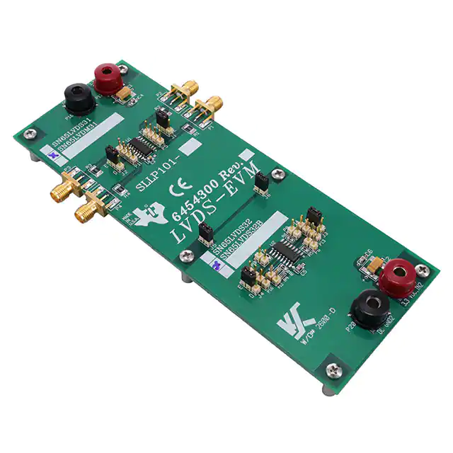
The SN65LVDS31–32BEVM includes the SN65LVDS31 quad driver and SN65LVDS32B quad receiver.
The SN65LVDS32B is a TIA/EIA-644 standard compliant LVDS receiver with extended common-mode
capabilities and an active fail-safe circuit. The SN65LVDS32B receivers operate over a commonmode
input voltage range of –2 V to 4.4 V, almost triple the operational rangerequired by the TIA/EIA–644
standard. The SN65LVDS32B’s active-failsafe circuit includes a window comparator that provides
operation over the entire input common-mode range. This allows for activation even when an external
common-mode voltage is applied to the bus. A photograph of the SN65LVDS31–32BEVM is shown in
Figure 1-1.
SLLU016C – August 2000 – Revised February 2010
Submit Documentation Feedback
Copyright © 2000–2010, Texas Instruments Incorporated
Introduction
5
�www.ti.com
Figure 1-1. SN65LVDS31/32B EVM Printed-Circuit Board
6
Introduction
SLLU016C – August 2000 – Revised February 2010
Submit Documentation Feedback
Copyright © 2000–2010, Texas Instruments Incorporated
�www.ti.com
Table 1-2. Jumper Functionality
JUMPER NUMBER
FUNCTION
JMP1, JMP3
Enable pin (active high)
High= shunt center pin to pin “V”
Low = shunt center pin to pin “G”
JMP2, JMP4
Enable pin (active low)
High= shunt center pin to pin “V”
Low = shunt center pin to pin “G”
JMP5, JMP6
Ground shifts
Installed = common GND and VDC
Uninstalled = different GND and VDC
P1, P2, P3, P4
Inputs to SN65LVDM31/SN65LVDS31 driver
P5, P7, P9, P11
Differential outputs of driver
P13, P14, P15, P16
Outputs from SN65LVDS32/SN65LVDS32B/SN65LVDS33 receiver
P6, P8, P10, P12
Differential inputs to receivers
The SN65LVDM31–32BEVM includes the SN65LVDM31 quad driver and SN65LVDS32B quad receiver.
The SN65LVDM31 is a multipoint LVDS driver that provides twice the drive current of standard LVDS
compliant drivers to allow operation in doubly-terminated (multipoint) topologies, heavily loaded bus lines,
or situations where increased noise margin is desired in a design. The SN65LVDM31 complies with the
driver requirements of the TIA/EIA–644 standard, except for this doubling of the output current.
The SN65LVDS31-33EVM includes the SN65LVDS31 quad driver and the SN65LVDS33 quad receiver.
The SN65LVDS33 is a TIA/EIA-644 standard compliant LVDS receiver. The SN65LVDS33 receiver
incorporates the widest common-mode input voltage range of –4 V to 5 V, as well as an active-failsafe
circuit that provides operation over the entire input common-mode range. The receiver also provides an
input voltage range specification compatible with a 5-V PECL signal. Precise control of the differential
input voltage threshold allows for inclusion of 50 mV of input voltage hysteresis to improve noise rejection
on slowly changing input signals.
TI also offers a family of LVDS receivers incorporating integrated terminations. This family of devices is
recognized by the LVDT string in their part numbers (e.g. SN65LVDT32B and SN65LVDTS33). The
SN65LVDT32B and SN65LVDT33B are pin compatible with the SN65LVDS32, the SN65LVDS32B, and
the SN65LVDS33. Although not offered on a separate EVM, user evaluation of the SN65LVDT32B and
the SN65LVDT33 is possible by user replacement of the receivers included on any of these EVMs.
Special EVM operating instructions are included below if evaluations of the SN65LVDT32B and
SN65LVDT33 are desired.
Reference will be made throughout the rest of this document to the SN65LVDS31 and the SN65LVDS32.
Recalling that the same PCB has been used for all four EVMs, and that EVM operation is identical for all
four modules, please read these as a reference to either of the drivers (SN65LVDS31 and SN65LVDM31)
and either of the receivers (SN65LVDS32, SN65LVDS32B, and SN65LVDS33). When special instructions
are necessary for any of the devices, explicit device references will be included. Likewise, future
references to the EVM should be understood to apply to any of the four available evaluation modules.
The EVM has been designed with the driver section on the top half of the board and the receiver section
on the bottom half. The installed quad driver is designated U1, while the quad receiver is designated U2.
The EVM, as delivered, incorporates 100-Ω termination resistors at the inputs to the four receivers (R5,
R6, R7, and R10). If the user desires to evaluate an SN65LVDT32B or an SN65LVDT33, these four
termination resistors must be removed.
Jumpers J5 and J6 are included to allow the driver and receiver portions of the board to either share the
same power and ground source, or be powered separately for independent device analysis. Removal of
these jumpers allows for the introduction of ground shifts between the driver and receiver, demonstrating
the wide common-mode operation of the SN65LVDS32B and the SN65LVDS33. Refer to Chapter 5 of this
user’s guide for guidelines on operating the EVM with forced ground shifts.
SLLU016C – August 2000 – Revised February 2010
Submit Documentation Feedback
Copyright © 2000–2010, Texas Instruments Incorporated
Introduction
7
�8
Introduction
SLLU016C – August 2000 – Revised February 2010
Submit Documentation Feedback
Copyright © 2000–2010, Texas Instruments Incorporated
�Chapter 2
SLLU016C – August 2000 – Revised February 2010
Equipment Required
This chapter provides a list of equipment required for the analysis of low-voltage differential signaling. It
also provides a schematic diagram and parts list.
q 3.3-VDC power supply (TEK-PS280 or equivalent)
q A transmission medium from the driver to the receiver (cable or wire)
q A function generator capable of supplying TTL level signaling rates of up to 400 Mbps. Note: 50-Ω
source impedance.
q A high-bandwidth oscilloscope, preferably in the 4-GHz range.
q Differential and single-ended oscilloscope probes.
SLLU016C – August 2000 – Revised February 2010
Submit Documentation Feedback
Copyright © 2000–2010, Texas Instruments Incorporated
Equipment Required
9
�www.ti.com
P4
P1
IN4
IN1
1
2
1
2
R1
49.9 W
Header 2x1
R4
49.9 W
VCC1
Header 2x2
Header 3x1
P11
Diff4_P
Diff4_N
Diff1_N
Diff1_P
1 3
2 4
VCC1
Header 2x1
1 3
2 4
VCC1
Header 2x2
P5
Header 3x1
Enable
Enable
1
1
Header 2x2
J1
Diff2_N
Diff2_P
J2
P9
Diff3_N
Diff3_P
1 3
2 4
LINE DRIVER
P7
1 3
2 4
VCC1
Header 2x2
P2
P17
IN2
1
2
P3
IN3
1
2
R2
49.9 W
Header 2x1
R3
49.9 W
1
C1
VCC1_3.3V 10 mF
+
C3
.01 mF
C4
.01 mF
Header 2x1
P18
1
GND
R9
0W
Diff40_N
P12
Diff10_N
Header 2x2
VCC2
Header 2x2
1 3
2 4
Diff10_P
P6
Diff40_P
J5
J6
1 3
2 4
R10
100 W
R5
100 W
P19
1
2
Header 2x1
1
2
Header 2x1
1
R8
0W
C2
VCC2_3.3V 10 mF
+
VCC2
C5
.01 mF
C6
.01 mF
P13
OUT1
VCC2
Header 3x1
1
2
Header 2x1
Enable1
1
J3
P14
1
2
OUT2
U2
1B
1A
1Y
G
2Y
2A
2B
GND
P20
P16
OUT4
VCC
4B
4A
4Y
G*
3Y
3A
3B
1
VCC2
1
2
GND
Header 3x1
Header 2x1
Enable1
1
P15
OUT3
LINE RECEIVER
Header 2x1
J4
1
2
Header 2x1
Diff20_P
Diff30_P
Header 2x2
1 3
2 4
P8
P10
R6
100 W
R7
100 W
Diff20_N
Diff30_N
1 3
2 4
Header 2x2
Figure 2-1. EVM Schematic Diagram
QUAD DRIVERS (U1)
EVM PCB
SN65LVDS31
SLLP101–1
X
SLLP101–2
X
SLLP101–3
SLLP101–4
10
Equipment Required
SN65LVDM31
QUAD RECEIVERS (U2)
SN65LVDS32
SN65LVDS32B
SN65LVDS33
X
X
X
X
X
X
SLLU016C – August 2000 – Revised February 2010
Submit Documentation Feedback
Copyright © 2000–2010, Texas Instruments Incorporated
�www.ti.com
Table 2-1. Parts List (SLLP101–1, SLLP101–2, SLLP101–3, and SLLP101–4)
ITEM
NO.
101-1
QTY.
101-2
QTY.
101-2
QTY.
101-4
QTY.
1
2
2
2
2
REF. DES.
DESCRIPTION
PART NUMBER
MFG.
C1, C2
Capacitor, 10.0 µF, tantalum
PCT3106TR–ND
Digi-Key
C3.C6
Capacitor, 0.01 µF
C0805C103K5RA
C
Mallory
J1.J4
3-Position male post with shorting 68001–236/65474– Berg Elec
jumpers
010
J5, J6
2-Position male post with shorting 68001–236/65474– Berg Elec
jumpers
010
2
4
4
4
4
3
4
4
4
4
4
2
2
2
2
5
4
4
4
4
P1–P4
Connectors, SMA, edgemount
528–S0101
Allied
6
8
8
8
8
P5–P12
2-Position female post, SIP
905–3090
Allied
7
4
4
4
4
P13–P16
2-Position male post
518–1052
Allied
8
4
4
4
4
P17–P20
Banana jack connectors, female
528–0172
Allied
9
4
4
4
4
R1–R4
Resistors, 51 Ω, 805 PK
P51GCT–ND
Digi-Key
10
3
3
3
3
R5–R7
Resistors, 100 Ω, 603 PK
P100GCT–ND
Digi-Key
11
2
2
2
2
R8–R9
Resistors, 0 Ω, 603 (optional:
45.3 Ω)
P0.0GCT–ND
Digi-Key
12
1
1
1
1
R10
Resistors, 100 Ω, 603 (optional:
10.22 Ω)
P100GCT–ND
Digi-Key
13
1
0
1
1
U1
IC, Quad driver
SN65LVDS31D
TI
14
0
1
0
0
U1
IC, Quad driver
SN65LVDM31D
TI
15
0
0
0
1
U2
IC, Quad receiver
SN65LVDS32D
TI
16
0
1
1
0
U2
IC, Quad receiver
SN65LVDS32BD
TI
17
1
0
0
0
U2
IC, Quad receiver
SN65LVDS33D
TI
J1–J6
Jumper short, (use with items 3
and 4)
65474–010
Allied
18
6
6
6
6
SLLU016C – August 2000 – Revised February 2010
Submit Documentation Feedback
Copyright © 2000–2010, Texas Instruments Incorporated
Equipment Required
11
�12
Equipment Required
SLLU016C – August 2000 – Revised February 2010
Submit Documentation Feedback
Copyright © 2000–2010, Texas Instruments Incorporated
�Chapter 3
SLLU016C – August 2000 – Revised February 2010
Point-to-Point Transmission
This chapter shows the setup for point-to-point transmission.
The point-to-point configuration with one driver transmitting to one receiver is a typical transmission
scheme. The transmission quality is superior, since there are no stubs and few discontinuities on the bus
to degrade the signal. Note that the required 100-Ω termination resistor (R5) is already in place across the
differential pair at the input of the receiver (U2).
Figure 3-1. Point-to-Point Schematic Diagram
SLLU016C – August 2000 – Revised February 2010
Submit Documentation Feedback
Copyright © 2000–2010, Texas Instruments Incorporated
Point-to-Point Transmission
13
�14
Point-to-Point Transmission
SLLU016C – August 2000 – Revised February 2010
Submit Documentation Feedback
Copyright © 2000–2010, Texas Instruments Incorporated
�Chapter 4
SLLU016C – August 2000 – Revised February 2010
Multidrop Transmission
This chapter shows the setup for multidrop transmission.
The multidrop configuration with one driver transmitting to several receivers may be implemented as
shown in Figure 4-1. In this application, only a single 100-Ω termination resistor is required across the
differential pair at the inputs of the last receiver. Termination resistors at the inputs of the middle receivers
in the configuration must be removed. To minimize reflections, line length between receivers should be
kept as short as possible. Stub length should also be kept to a minimum. On the EVM, stub length is
approximately 3 cm.
For a complete discussion of this configuration with up to 36 receivers, consult the TI application note,
LVDS Multidrop Connections, literature number SLLA054.
Termination resistors R5, R6, and R7 must be removed.
Figure 4-1. Multidrop Schematic Diagram
SLLU016C – August 2000 – Revised February 2010
Submit Documentation Feedback
Copyright © 2000–2010, Texas Instruments Incorporated
Multidrop Transmission
15
�16
Multidrop Transmission
SLLU016C – August 2000 – Revised February 2010
Submit Documentation Feedback
Copyright © 2000–2010, Texas Instruments Incorporated
�Chapter 5
SLLU016C – August 2000 – Revised February 2010
Evaluation of Receiver Operation During Ground Shifts
This chapter explains how to introduce ground shifts between the driver and the receiver to test the
receiver operation over its full common-mode voltage input range.
LVDS driver outputs have an offset voltage of approximately 1.2 V. The SN65LVDS32 receiver complies
with the TIA/EIA–644 standard. It correctly detects the logic level of the input signal when 100 mV of
differential signal is present at its input, and the input common-mode voltage is between 0 V and 2.4 V.
(The actual input common-mode range is also dependent upon the differential input voltage; see
recommended operating condition in the data sheet for dependency.) The SN65LVDS32B provides
operation over an input common-mode voltage range of –2 V to 4.4 V, whereas the SN65LVDS33 extends
the operation to an input common-mode voltage range of –4 V to 5 V. Both the above mentioned receivers
are equipped to correctly detect the input state with a 50-mV differential signal at its input.
input state with a 50-mV differential signal at its input. All EVMs can be used to evaluate the receiver
operation in the presence of ground shifts between the driver and receiver. Testing of EVMs that host a
SN65LVDS32B or a SN65LVDS33 will demonstrate the extended range operation of these devices.
Perform the following steps to demonstrate operation during ground shifts.
1. Remove the jumper shorts on jumpers J5 and J6.
Three dc power supplies will be used for this test.
2. Using the first power supply (PS1), apply 3.3-V power to the driver section of the EVM (via connectors
P17 and P18).
3. Using the second power supply (PS2), apply 3.3-V power to the receiver section of the EVM (via
connectors P19 and P20).
4. Tie the third power supply (PS3) between the grounds of PS1 and PS2.
5. Initially set PS3 to 0 V.
6. Input a test signal to the driver while monitoring the output of a receiver (refer to Chapter 3,
Point-to-Point Transmission).
7. Vary the ground shift between the driver and the receiver via adjustments to PS3.
A test setup is shown in Figure 5-1.
SLLU016C – August 2000 – Revised February 2010
Submit Documentation Feedback
Evaluation of Receiver Operation During Ground Shifts
Copyright © 2000–2010, Texas Instruments Incorporated
17
�www.ti.com
Figure 5-1. Test Setup
18
Evaluation of Receiver Operation During Ground Shifts
SLLU016C – August 2000 – Revised February 2010
Submit Documentation Feedback
Copyright © 2000–2010, Texas Instruments Incorporated
�Chapter 6
SLLU016C – August 2000 – Revised February 2010
The Application of TIA/EIA-422 Data to an LVDS Receiver
This chapter explains the application of TIA/EIA-422 data into an LVDS receiver.
The fourth channel of the receiver (4A and 4B) configured with the resistor divider network of R8, R9, and
R10 may be used for the evaluation of TIA/EIA-422 data applied to an LVDS receiver. TIA/EIA-422
signaling voltage levels are adjusted to appropriate LVDS input voltage levels by installing 45-Ω resistors
in the spaces provided for R8 and R9 on the evaluation board. The 100-Ω resistor (R10) must then be
removed and replaced with a 10-Ω resistor as shown in Figure 6-1. This resistor divider network now
comprises a total differential load of 100 Ω to match the characteristic impedance of a common
transmission line, and reduces the TIA/EIA-422 maximum differential signal amplitude from 6 V to an
appropriate 600 mV.
Figure 6-1. TIA/EIA-422 Data to an LVDS Receiver Schematic
SLLU016C – August 2000 – Revised February 2010
Submit Documentation Feedback
The Application of TIA/EIA-422 Data to an LVDS Receiver
Copyright © 2000–2010, Texas Instruments Incorporated
19
�20
The Application of TIA/EIA-422 Data to an LVDS Receiver
SLLU016C – August 2000 – Revised February 2010
Submit Documentation Feedback
Copyright © 2000–2010, Texas Instruments Incorporated
�Chapter 7
SLLU016C – August 2000 – Revised February 2010
References
This chapter contains a list of LVDS literature available.
There is a wide selection of the LVDS devices and related applications materials available to assist in the
design and development of LVDS interfaces. This information is located at www.ti.com/sc/datatran. Input
LVDS into the search tool or enter the part number of a specific device to obtain additional information.
1. LVDS Designer’s Notes (literature number SLLA014A)
2. Reducing EMI With Low Voltage Differential Signaling (literature number SLLA030)
3. The Active Fail-Safe Feature of the SN65LVDS32B (literature number SLLA082)
4. A statistical Survey of Common-Mode Noise (literature number SLLA057)
5. Measuring Crosstalk in LVDS Systems (literature number SLLA064)
6. Interface Circuits for TIA/EIA–644 (LVDS) (literature number SLLA038)
7. Transmission at 200 Mbps in VME Card Cage Using LVDM (literature number SLLA088)
8. Performance of LVDS With Different Cables (literature number SLLA053)
9. LVDS Multidrop Connections (literature number SLLA054)
SLLU016C – August 2000 – Revised February 2010
Submit Documentation Feedback
Copyright © 2000–2010, Texas Instruments Incorporated
References
21
�IMPORTANT NOTICE
Texas Instruments Incorporated and its subsidiaries (TI) reserve the right to make corrections, modifications, enhancements, improvements,
and other changes to its products and services at any time and to discontinue any product or service without notice. Customers should
obtain the latest relevant information before placing orders and should verify that such information is current and complete. All products are
sold subject to TI’s terms and conditions of sale supplied at the time of order acknowledgment.
TI warrants performance of its hardware products to the specifications applicable at the time of sale in accordance with TI’s standard
warranty. Testing and other quality control techniques are used to the extent TI deems necessary to support this warranty. Except where
mandated by government requirements, testing of all parameters of each product is not necessarily performed.
TI assumes no liability for applications assistance or customer product design. Customers are responsible for their products and
applications using TI components. To minimize the risks associated with customer products and applications, customers should provide
adequate design and operating safeguards.
TI does not warrant or represent that any license, either express or implied, is granted under any TI patent right, copyright, mask work right,
or other TI intellectual property right relating to any combination, machine, or process in which TI products or services are used. Information
published by TI regarding third-party products or services does not constitute a license from TI to use such products or services or a
warranty or endorsement thereof. Use of such information may require a license from a third party under the patents or other intellectual
property of the third party, or a license from TI under the patents or other intellectual property of TI.
Reproduction of TI information in TI data books or data sheets is permissible only if reproduction is without alteration and is accompanied
by all associated warranties, conditions, limitations, and notices. Reproduction of this information with alteration is an unfair and deceptive
business practice. TI is not responsible or liable for such altered documentation. Information of third parties may be subject to additional
restrictions.
Resale of TI products or services with statements different from or beyond the parameters stated by TI for that product or service voids all
express and any implied warranties for the associated TI product or service and is an unfair and deceptive business practice. TI is not
responsible or liable for any such statements.
TI products are not authorized for use in safety-critical applications (such as life support) where a failure of the TI product would reasonably
be expected to cause severe personal injury or death, unless officers of the parties have executed an agreement specifically governing
such use. Buyers represent that they have all necessary expertise in the safety and regulatory ramifications of their applications, and
acknowledge and agree that they are solely responsible for all legal, regulatory and safety-related requirements concerning their products
and any use of TI products in such safety-critical applications, notwithstanding any applications-related information or support that may be
provided by TI. Further, Buyers must fully indemnify TI and its representatives against any damages arising out of the use of TI products in
such safety-critical applications.
TI products are neither designed nor intended for use in military/aerospace applications or environments unless the TI products are
specifically designated by TI as military-grade or "enhanced plastic." Only products designated by TI as military-grade meet military
specifications. Buyers acknowledge and agree that any such use of TI products which TI has not designated as military-grade is solely at
the Buyer's risk, and that they are solely responsible for compliance with all legal and regulatory requirements in connection with such use.
TI products are neither designed nor intended for use in automotive applications or environments unless the specific TI products are
designated by TI as compliant with ISO/TS 16949 requirements. Buyers acknowledge and agree that, if they use any non-designated
products in automotive applications, TI will not be responsible for any failure to meet such requirements.
Following are URLs where you can obtain information on other Texas Instruments products and application solutions:
Products
Applications
Amplifiers
amplifier.ti.com
Audio
www.ti.com/audio
Data Converters
dataconverter.ti.com
Automotive
www.ti.com/automotive
DLP® Products
www.dlp.com
Communications and
Telecom
www.ti.com/communications
DSP
dsp.ti.com
Computers and
Peripherals
www.ti.com/computers
Clocks and Timers
www.ti.com/clocks
Consumer Electronics
www.ti.com/consumer-apps
Interface
interface.ti.com
Energy
www.ti.com/energy
Logic
logic.ti.com
Industrial
www.ti.com/industrial
Power Mgmt
power.ti.com
Medical
www.ti.com/medical
Microcontrollers
microcontroller.ti.com
Security
www.ti.com/security
RFID
www.ti-rfid.com
Space, Avionics &
Defense
www.ti.com/space-avionics-defense
RF/IF and ZigBee® Solutions www.ti.com/lprf
Video and Imaging
www.ti.com/video
Wireless
www.ti.com/wireless-apps
Mailing Address: Texas Instruments, Post Office Box 655303, Dallas, Texas 75265
Copyright © 2010, Texas Instruments Incorporated
�