SN54BCT541, SN74BCT541A
OCTAL BUFFERS/DRIVERS
WITH 3-STATE OUTPUTS
SCBS011E – JULY 1988 – REVISED MARCH 2003
D
D
D
Operating Voltage Range of 4.5 V to 5.5 V
State-of-the-Art BiCMOS Design
Significantly Reduces ICCZ
3-State Outputs Drive Bus Lines or Buffer
Memory Address Registers
P-N-P Inputs Reduce DC Loading
Data Flow-Through Pinout (All Inputs on
Opposite Side From Outputs)
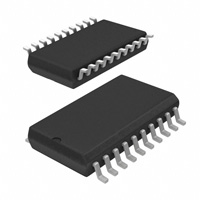
SN54BCT541 . . . J OR W PACKAGE
SN74BCT541A . . . DW, N, OR NS PACKAGE
(TOP VIEW)
1
20
2
19
3
18
4
17
5
16
6
15
7
14
8
13
9
12
10
11
A2
A1
OE1
VCC
VCC
OE2
Y1
Y2
Y3
Y4
Y5
Y6
Y7
Y8
A3
A4
A5
A6
A7
4
3 2 1 20 19
18
5
17
6
16
7
15
8
14
9 10 11 12 13
Y1
Y2
Y3
Y4
Y5
A8
GND
Y8
Y7
Y6
OE1
A1
A2
A3
A4
A5
A6
A7
A8
GND
SN54BCT541 . . . FK PACKAGE
(TOP VIEW)
OE2
D
D
description/ordering information
The SN54BCT541 and SN74BCT541A octal buffers and line drivers are ideal for driving bus lines or buffering
memory-address registers. The devices feature inputs and outputs on opposite sides of the package to facilitate
printed-circuit-board layout.
The 3-state control gate is a 2-input AND gate with active-low inputs so that, if either output-enable (OE1 or OE2)
input is high, all eight outputs are in the high-impedance state.
To ensure the high-impedance state during power up or power down, OE should be tied to VCC through a pullup
resistor; the minimum value of the resistor is determined by the current-sinking capability of the driver.
ORDERING INFORMATION
PDIP – N
0°C to 70°C
–55°C to 125°C
ORDERABLE
PART NUMBER
PACKAGE†
TA
TOP-SIDE
MARKING
Tube
SN74BCT541AN
Tube
SN74BCT541ADW
Tape and reel
SN74BCT541ADWR
SOP – NS
Tape and reel
SN74BCT541ANSR
BCT541A
CDIP – J
Tube
SNJ54BCT541J
SNJ54BCT541J
CFP – W
Tube
SNJ54BCT541W
SNJ54BCT541W
LCCC – FK
Tube
SNJ54BCT541FK
SOIC – DW
SN74BCT541AN
BCT541A
SNJ54BCT541FK
† Package drawings, standard packing quantities, thermal data, symbolization, and PCB design guidelines are
available at www.ti.com/sc/package.
Please be aware that an important notice concerning availability, standard warranty, and use in critical applications of
Texas Instruments semiconductor products and disclaimers thereto appears at the end of this data sheet.
Copyright 2003, Texas Instruments Incorporated
PRODUCTION DATA information is current as of publication date.
Products conform to specifications per the terms of Texas Instruments
standard warranty. Production processing does not necessarily include
testing of all parameters.
On products compliant to MIL-PRF-38535, all parameters are tested
unless otherwise noted. On all other products, production
processing does not necessarily include testing of all parameters.
POST OFFICE BOX 655303
• DALLAS, TEXAS 75265
1
�SN54BCT541, SN74BCT541A
OCTAL BUFFERS/DRIVERS
WITH 3-STATE OUTPUTS
SCBS011E – JULY 1988 – REVISED MARCH 2003
FUNCTION TABLE
INPUTS
A
OUTPUT
Y
OE1
OE2
L
L
L
L
L
L
H
H
H
X
X
Z
X
H
X
Z
logic diagram (positive logic)
OE1
OE2
A1
1
19
2
18
Y1
To Seven Other Channels
absolute maximum ratings over operating free-air temperature range (unless otherwise noted)†
Supply voltage range, VCC . . . . . . . . . . . . . . . . . . . . . . . . . . . . . . . . . . . . . . . . . . . . . . . . . . . . . . . . . . –0.5 V to 7 V
Input voltage range, VI (see Note 1) . . . . . . . . . . . . . . . . . . . . . . . . . . . . . . . . . . . . . . . . . . . . . . . . . . –0.5 V to 7 V
Voltage range applied to any output in the disabled or power-off state, VO . . . . . . . . . . . . . . . . –0.5 V to 5.5 V
Voltage range applied to any output in the high state, VO . . . . . . . . . . . . . . . . . . . . . . . . . . . . . . . –0.5 V to VCC
Current into any output in the low state: SN54BCT541 . . . . . . . . . . . . . . . . . . . . . . . . . . . . . . . . . . . . . . . 96 mA
SN74BCT541A . . . . . . . . . . . . . . . . . . . . . . . . . . . . . . . . . . . . . 128 mA
Package thermal impedance, θJA (see Note 2): DW package . . . . . . . . . . . . . . . . . . . . . . . . . . . . . . . . . 58°C/W
N package . . . . . . . . . . . . . . . . . . . . . . . . . . . . . . . . . . . 69°C/W
NS package . . . . . . . . . . . . . . . . . . . . . . . . . . . . . . . . . 60°C/W
Storage temperature range, Tstg . . . . . . . . . . . . . . . . . . . . . . . . . . . . . . . . . . . . . . . . . . . . . . . . . . . –65°C to 150°C
† Stresses beyond those listed under “absolute maximum ratings” may cause permanent damage to the device. These are stress ratings only, and
functional operation of the device at these or any other conditions beyond those indicated under “recommended operating conditions” is not
implied. Exposure to absolute-maximum-rated conditions for extended periods may affect device reliability.
NOTES: 1. The input and output voltage ratings may be exceeded if the input and output current ratings are observed.
2. The package thermal impedance is calculated in accordance with JESD 51-7.
recommended operating conditions (see Note 3)
SN54BCT541
SN74BCT541A
MIN
NOM
MAX
MIN
NOM
MAX
4.5
5
5.5
4.5
5
5.5
UNIT
VCC
VIH
Supply voltage
VIL
IIK
Low-level input voltage
0.8
0.8
V
Input clamp current
–18
–18
mA
IOH
IOL
High-level output current
–12
–15
mA
Low-level output current
48
64
mA
High-level input voltage
2
2
V
V
TA
Operating free-air temperature
–55
125
0
70
°C
NOTE 3: All unused inputs of the device must be held at VCC or GND to ensure proper device operation. Refer to the TI application report,
Implications of Slow or Floating CMOS Inputs, literature number SCBA004.
2
POST OFFICE BOX 655303
• DALLAS, TEXAS 75265
�SN54BCT541, SN74BCT541A
OCTAL BUFFERS/DRIVERS
WITH 3-STATE OUTPUTS
SCBS011E – JULY 1988 – REVISED MARCH 2003
electrical characteristics over recommended operating free-air temperature range (unless
otherwise noted)
PARAMETER
VIK
VOH
SN54BCT541
TYP†
MAX
TEST CONDITIONS
VCC = 4.5 V,
VCC = 4.5 V
MIN
II = –18 mA
IOH = –3 mA
SN74BCT541A
TYP†
MAX
MIN
–1.2
2.4
3.3
2
3.2
IOH = –12 mA
IOH = –15 mA
–1.2
2.4
V
3.3
V
2
0.38
UNIT
3.1
VOL
VCC = 4
4.5
5V
IOL = 48 mA
IOL = 64 mA
0.55
II
IIH
VCC = 5.5 V,
VCC = 5.5 V,
VI = 7 V
VI = 2.7 V
0.1
0.1
mA
20
20
µA
IIL
IOZH
VCC = 5.5 V,
VCC = 5.5 V,
VI = 0.5 V
VO = 2.7 V
–0.6
–0.6
mA
50
50
µA
IOZL
IOS‡
VCC = 5.5 V,
VCC = 5.5 V,
VO = 0.5 V
VO = 0
–50
–50
µA
ICCH
ICCL
VCC = 5.5 V
VCC = 5.5 V
ICCZ
Ci
VCC = 5.5 V
VCC = 5 V,
0.42
–100
–225
V
–225
mA
27
40
27
40
mA
47
72
47
72
mA
5
7
5
7
mA
VI = 2.5 V or 0.5 V
VO = 2.5 V or 0.5 V
–100
0.55
5
Co
VCC = 5 V,
10
† All typical values are at VCC = 5 V, TA = 25°C.
‡ Not more than one output should be tested at a time, and the duration of the test should not exceed one second.
5
pF
10
pF
switching characteristics (see Figure 1)
PARAMETER
FROM
(INPUT)
TO
(OUTPUT)
VCC = 5 V,
CL = 50 pF,
R1 = 500 Ω,
R2 = 500 Ω,
TA = 25°C
VCC = 4.5 V to 5.5 V,
CL = 50 pF,
R1 = 500 Ω,
R2 = 500 Ω,
TA = MIN to MAX§
’BCT541
tPLH
tPHL
A
Y
tPZH
tPZL
OE
Y
tPHZ
tPLZ
OE
Y
SN54BCT541
UNIT
SN74BCT541A
MIN
TYP
MAX
MIN
MAX
MIN
2.1
3.7
5.3
1.7
6.3
1.7
MAX
6
3.7
5.5
7.5
3.2
8.7
3.4
8.2
4.5
7.2
9.3
4.4
11
3.9
10.7
5
8
10.4
5.4
12.4
4.4
11.5
3.5
5.6
7.6
3
9.1
3
8.6
3.4
5.2
7.2
3
9.4
3
8.6
ns
ns
ns
§ For conditions shown as MIN or MAX, use the appropriate value specified under recommended operating conditions.
POST OFFICE BOX 655303
• DALLAS, TEXAS 75265
3
�SN54BCT541, SN74BCT541A
OCTAL BUFFERS/DRIVERS
WITH 3-STATE OUTPUTS
SCBS011E – JULY 1988 – REVISED MARCH 2003
PARAMETER MEASUREMENT INFORMATION
7 V (tPZL, tPLZ, O.C.)
S1
Open
(all others)
From Output
Under Test
Test
Point
CL
(see Note A)
R1
From Output
Under Test
R1
Test
Point
CL
(see Note A)
R2
LOAD CIRCUIT FOR
TOTEM-POLE OUTPUTS
RL = R1 = R2
LOAD CIRCUIT FOR
3-STATE AND OPEN-COLLECTOR OUTPUTS
High-Level
Pulse
(see Note B)
3V
Timing Input
(see Note B)
3V
1.5 V
1.5 V
0V
1.5 V
tw
0V
Data Input
(see Note B)
3V
th
tsu
Low-Level
Pulse
3V
1.5 V
1.5 V
0V
1.5 V
1.5 V
VOLTAGE WAVEFORMS
PULSE DURATION
0V
VOLTAGE WAVEFORMS
SETUP AND HOLD TIMES
3V
Output
Control
(low-level enable)
3V
Input
(see Note B)
1.5 V
1.5 V
0V
tPLH
In-Phase
Output
(see Note D)
1.5 V
VOL
VOH
1.5 V
1.5 V
0V
tPLZ
1.5 V
Waveform 1
(see Notes C and D)
3.5 V
VOL
tPHZ
tPLH
tPHL
Out-of-Phase
Output
(see Note D)
1.5 V
1.5 V
tPZL
tPHL
VOH
1.5 V
0.3 V
tPZH
Waveform 2
(see Notes C and D)
VOL
VOLTAGE WAVEFORMS
PROPAGATION DELAY TIMES (see Note D)
VOH
1.5 V
0.3 V
0V
VOLTAGE WAVEFORMS
ENABLE AND DISABLE TIMES, 3-STATE OUTPUTS
NOTES: A. CL includes probe and jig capacitance.
B. All input pulses are supplied by generators having the following characteristics: PRR ≤ 10 MHz, tr = tf ≤ 2.5 ns, duty cycle = 50%.
C. Waveform 1 is for an output with internal conditions such that the output is low except when disabled by the output control.
Waveform 2 is for an output with internal conditions such that the output is high except when disabled by the output control.
D. The outputs are measured one at a time with one transition per measurement.
E. When measuring propagation delay times of 3-state outputs, switch S1 is open.
F. All parameters and waveforms are not applicable to all devices.
Figure 1. Load Circuit and Voltage Waveforms
4
POST OFFICE BOX 655303
• DALLAS, TEXAS 75265
�PACKAGE OPTION ADDENDUM
www.ti.com
15-Oct-2009
PACKAGING INFORMATION
Orderable Device
Status (1)
Package
Type
Package
Drawing
Pins Package Eco Plan (2)
Qty
5962-9074901M2A
ACTIVE
LCCC
FK
20
1
TBD
5962-9074901MRA
ACTIVE
CDIP
J
20
1
TBD
5962-9074901MSA
ACTIVE
CFP
W
20
1
SN74BCT541ADW
ACTIVE
SOIC
DW
20
25
SN74BCT541ADWE4
ACTIVE
SOIC
DW
20
25
SN74BCT541ADWG4
ACTIVE
SOIC
DW
20
25
SN74BCT541ADWR
ACTIVE
SOIC
DW
SN74BCT541ADWRE4
ACTIVE
SOIC
SN74BCT541ADWRG4
ACTIVE
SN74BCT541AN
Lead/Ball Finish
MSL Peak Temp (3)
POST-PLATE N / A for Pkg Type
A42
N / A for Pkg Type
TBD
Call TI
N / A for Pkg Type
Green (RoHS &
no Sb/Br)
CU NIPDAU
Level-1-260C-UNLIM
Green (RoHS &
no Sb/Br)
CU NIPDAU
Level-1-260C-UNLIM
Green (RoHS &
no Sb/Br)
CU NIPDAU
Level-1-260C-UNLIM
20
2000 Green (RoHS &
no Sb/Br)
CU NIPDAU
Level-1-260C-UNLIM
DW
20
2000 Green (RoHS &
no Sb/Br)
CU NIPDAU
Level-1-260C-UNLIM
SOIC
DW
20
2000 Green (RoHS &
no Sb/Br)
CU NIPDAU
Level-1-260C-UNLIM
ACTIVE
PDIP
N
20
20
Pb-Free
(RoHS)
CU NIPDAU
N / A for Pkg Type
SN74BCT541ANE4
ACTIVE
PDIP
N
20
20
Pb-Free
(RoHS)
CU NIPDAU
N / A for Pkg Type
SN74BCT541ANSR
ACTIVE
SO
NS
20
2000 Green (RoHS &
no Sb/Br)
CU NIPDAU
Level-1-260C-UNLIM
SN74BCT541ANSRE4
ACTIVE
SO
NS
20
2000 Green (RoHS &
no Sb/Br)
CU NIPDAU
Level-1-260C-UNLIM
SN74BCT541ANSRG4
ACTIVE
SO
NS
20
2000 Green (RoHS &
no Sb/Br)
CU NIPDAU
Level-1-260C-UNLIM
SNJ54BCT541FK
ACTIVE
LCCC
FK
20
1
TBD
SNJ54BCT541J
ACTIVE
CDIP
J
20
1
TBD
A42
N / A for Pkg Type
SNJ54BCT541W
ACTIVE
CFP
W
20
1
TBD
Call TI
N / A for Pkg Type
POST-PLATE N / A for Pkg Type
(1)
The marketing status values are defined as follows:
ACTIVE: Product device recommended for new designs.
LIFEBUY: TI has announced that the device will be discontinued, and a lifetime-buy period is in effect.
NRND: Not recommended for new designs. Device is in production to support existing customers, but TI does not recommend using this part in
a new design.
PREVIEW: Device has been announced but is not in production. Samples may or may not be available.
OBSOLETE: TI has discontinued the production of the device.
(2)
Eco Plan - The planned eco-friendly classification: Pb-Free (RoHS), Pb-Free (RoHS Exempt), or Green (RoHS & no Sb/Br) - please check
http://www.ti.com/productcontent for the latest availability information and additional product content details.
TBD: The Pb-Free/Green conversion plan has not been defined.
Pb-Free (RoHS): TI's terms "Lead-Free" or "Pb-Free" mean semiconductor products that are compatible with the current RoHS requirements
for all 6 substances, including the requirement that lead not exceed 0.1% by weight in homogeneous materials. Where designed to be soldered
at high temperatures, TI Pb-Free products are suitable for use in specified lead-free processes.
Pb-Free (RoHS Exempt): This component has a RoHS exemption for either 1) lead-based flip-chip solder bumps used between the die and
package, or 2) lead-based die adhesive used between the die and leadframe. The component is otherwise considered Pb-Free (RoHS
compatible) as defined above.
Green (RoHS & no Sb/Br): TI defines "Green" to mean Pb-Free (RoHS compatible), and free of Bromine (Br) and Antimony (Sb) based flame
retardants (Br or Sb do not exceed 0.1% by weight in homogeneous material)
(3)
MSL, Peak Temp. -- The Moisture Sensitivity Level rating according to the JEDEC industry standard classifications, and peak solder
temperature.
Addendum-Page 1
�PACKAGE OPTION ADDENDUM
www.ti.com
15-Oct-2009
Important Information and Disclaimer:The information provided on this page represents TI's knowledge and belief as of the date that it is
provided. TI bases its knowledge and belief on information provided by third parties, and makes no representation or warranty as to the
accuracy of such information. Efforts are underway to better integrate information from third parties. TI has taken and continues to take
reasonable steps to provide representative and accurate information but may not have conducted destructive testing or chemical analysis on
incoming materials and chemicals. TI and TI suppliers consider certain information to be proprietary, and thus CAS numbers and other limited
information may not be available for release.
In no event shall TI's liability arising out of such information exceed the total purchase price of the TI part(s) at issue in this document sold by TI
to Customer on an annual basis.
OTHER QUALIFIED VERSIONS OF SN54BCT541 :
• Catalog: SN74BCT541
NOTE: Qualified Version Definitions:
• Catalog - TI's standard catalog product
Addendum-Page 2
�PACKAGE MATERIALS INFORMATION
www.ti.com
5-Aug-2008
TAPE AND REEL INFORMATION
*All dimensions are nominal
Device
Package Package Pins
Type Drawing
SPQ
Reel
Reel
Diameter Width
(mm) W1 (mm)
A0 (mm)
B0 (mm)
K0 (mm)
P1
(mm)
W
Pin1
(mm) Quadrant
SN74BCT541ADWR
SOIC
DW
20
2000
330.0
24.4
10.8
13.0
2.7
12.0
24.0
Q1
SN74BCT541ANSR
SO
NS
20
2000
330.0
24.4
8.2
13.0
2.5
12.0
24.0
Q1
Pack Materials-Page 1
�PACKAGE MATERIALS INFORMATION
www.ti.com
5-Aug-2008
*All dimensions are nominal
Device
Package Type
Package Drawing
Pins
SPQ
Length (mm)
Width (mm)
Height (mm)
SN74BCT541ADWR
SOIC
DW
20
2000
346.0
346.0
41.0
SN74BCT541ANSR
SO
NS
20
2000
346.0
346.0
41.0
Pack Materials-Page 2
�MECHANICAL DATA
MLCC006B – OCTOBER 1996
FK (S-CQCC-N**)
LEADLESS CERAMIC CHIP CARRIER
28 TERMINAL SHOWN
18
17
16
15
14
13
NO. OF
TERMINALS
**
12
19
11
20
10
A
B
MIN
MAX
MIN
MAX
20
0.342
(8,69)
0.358
(9,09)
0.307
(7,80)
0.358
(9,09)
28
0.442
(11,23)
0.458
(11,63)
0.406
(10,31)
0.458
(11,63)
21
9
22
8
44
0.640
(16,26)
0.660
(16,76)
0.495
(12,58)
0.560
(14,22)
23
7
52
0.739
(18,78)
0.761
(19,32)
0.495
(12,58)
0.560
(14,22)
24
6
68
0.938
(23,83)
0.962
(24,43)
0.850
(21,6)
0.858
(21,8)
84
1.141
(28,99)
1.165
(29,59)
1.047
(26,6)
1.063
(27,0)
B SQ
A SQ
25
5
26
27
28
1
2
3
4
0.080 (2,03)
0.064 (1,63)
0.020 (0,51)
0.010 (0,25)
0.020 (0,51)
0.010 (0,25)
0.055 (1,40)
0.045 (1,14)
0.045 (1,14)
0.035 (0,89)
0.045 (1,14)
0.035 (0,89)
0.028 (0,71)
0.022 (0,54)
0.050 (1,27)
4040140 / D 10/96
NOTES: A.
B.
C.
D.
E.
All linear dimensions are in inches (millimeters).
This drawing is subject to change without notice.
This package can be hermetically sealed with a metal lid.
The terminals are gold plated.
Falls within JEDEC MS-004
POST OFFICE BOX 655303
• DALLAS, TEXAS 75265
������PACKAGE OPTION ADDENDUM
www.ti.com
18-Aug-2022
PACKAGING INFORMATION
Orderable Device
Status
(1)
Package Type Package Pins Package
Drawing
Qty
Eco Plan
(2)
Lead finish/
Ball material
MSL Peak Temp
Op Temp (°C)
Device Marking
(3)
Samples
(4/5)
(6)
5962-9074901M2A
ACTIVE
LCCC
FK
20
1
Non-RoHS
& Green
SNPB
N / A for Pkg Type
-55 to 125
59629074901M2A
SNJ54BCT
541FK
5962-9074901MRA
ACTIVE
CDIP
J
20
1
Non-RoHS
& Green
SNPB
N / A for Pkg Type
-55 to 125
5962-9074901MR
A
SNJ54BCT541J
SN74BCT541ADW
ACTIVE
SOIC
DW
20
25
RoHS & Green
NIPDAU
Level-1-260C-UNLIM
0 to 70
BCT541A
Samples
SN74BCT541ADWR
ACTIVE
SOIC
DW
20
2000
RoHS & Green
NIPDAU
Level-1-260C-UNLIM
0 to 70
BCT541A
Samples
SN74BCT541AN
ACTIVE
PDIP
N
20
20
RoHS &
Non-Green
NIPDAU
N / A for Pkg Type
0 to 70
SN74BCT541AN
Samples
SN74BCT541ANSR
ACTIVE
SO
NS
20
2000
RoHS & Green
NIPDAU
Level-1-260C-UNLIM
0 to 70
BCT541A
Samples
SNJ54BCT541FK
ACTIVE
LCCC
FK
20
1
Non-RoHS
& Green
SNPB
N / A for Pkg Type
-55 to 125
59629074901M2A
SNJ54BCT
541FK
SNJ54BCT541J
ACTIVE
CDIP
J
20
1
Non-RoHS
& Green
SNPB
N / A for Pkg Type
-55 to 125
5962-9074901MR
A
SNJ54BCT541J
(1)
The marketing status values are defined as follows:
ACTIVE: Product device recommended for new designs.
LIFEBUY: TI has announced that the device will be discontinued, and a lifetime-buy period is in effect.
NRND: Not recommended for new designs. Device is in production to support existing customers, but TI does not recommend using this part in a new design.
PREVIEW: Device has been announced but is not in production. Samples may or may not be available.
OBSOLETE: TI has discontinued the production of the device.
(2)
RoHS: TI defines "RoHS" to mean semiconductor products that are compliant with the current EU RoHS requirements for all 10 RoHS substances, including the requirement that RoHS substance
do not exceed 0.1% by weight in homogeneous materials. Where designed to be soldered at high temperatures, "RoHS" products are suitable for use in specified lead-free processes. TI may
reference these types of products as "Pb-Free".
RoHS Exempt: TI defines "RoHS Exempt" to mean products that contain lead but are compliant with EU RoHS pursuant to a specific EU RoHS exemption.
Green: TI defines "Green" to mean the content of Chlorine (Cl) and Bromine (Br) based flame retardants meet JS709B low halogen requirements of


 工商网监
湘ICP备2023018690号
工商网监
湘ICP备2023018690号
