SN74GTLP1395
TWO 1-BIT LVTTL-TO-GTLP ADJUSTABLE-EDGE-RATE BUS TRANSCEIVERS
WITH SPLIT LVTTL PORT, FEEDBACK PATH, AND SELECTABLE POLARITY
SCES349C – JUNE 2001 – REVISED NOVEMBER 2001
D
D
D
D
D
D
D
D
D
D
D
D
TI-OPC Circuitry Limits Ringing on
Unevenly Loaded Backplanes
OEC Circuitry Improves Signal Integrity
and Reduces Electromagnetic Interference
Bidirectional Interface Between GTLP
Signal Levels and LVTTL Logic Levels
Split LVTTL Port Provides a Feedback Path
for Control and Diagnostics Monitoring
LVTTL Interfaces Are 5-V Tolerant
High-Drive GTLP Outputs (100 mA)
LVTTL Outputs (–24 mA/24 mA)
Variable Edge-Rate Control (ERC) Input
Selects GTLP Rise and Fall Times for
Optimal Data-Transfer Rate and Signal
Integrity in Distributed Loads
Ioff, Power-Up 3-State, and BIAS VCC
Support Live Insertion
Polarity Control Selects True or
Complementary Outputs
Latch-Up Performance Exceeds 100 mA Per
JESD 78, Class II
ESD Protection Exceeds JESD 22
– 2000-V Human-Body Model (A114-A)
– 200-V Machine Model (A115-A)
– 1000-V Charged-Device Model (C101)
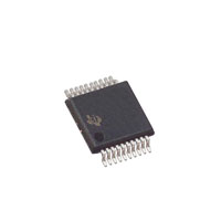
DGV, DW, OR PW PACKAGE
(TOP VIEW)
1Y
1T/C
2Y
GND
1OEAB
VCC
1A
GND
2A
2OEAB
1
20
2
19
3
18
4
17
5
16
6
15
7
14
8
13
9
12
10
11
1OEBY
2T/C
2OEBY
GND
1B
ERC
2B
GND
VREF
BIAS VCC
description
The SN74GTLP1395 is two 1-bit, high-drive, 3-wire bus transceivers that provide LVTTL-to-GTLP and
GTLP-to-LVTTL signal-level translation for applications, such as primary and secondary clocks, that require
individual output-enable and true/complement controls. The device allows for transparent and inverted
transparent modes of data transfer with separate LVTTL input and LVTTL output pins, which provide a feedback
path for control and diagnostics monitoring. The device provides a high-speed interface between cards
operating at LVTTL logic levels and a backplane operating at GTLP signal levels and is designed especially to
work with the Texas Instruments 3.3-V 1394 backplane physical-layer controller. High-speed (about three times
faster than standard LVTTL or TTL) backplane operation is a direct result of GTLP reduced output swing ( VCC.
3. The package thermal impedance is calculated in accordance with JESD 51-7.
POST OFFICE BOX 655303
• DALLAS, TEXAS 75265
5
�SN74GTLP1395
TWO 1-BIT LVTTL-TO-GTLP ADJUSTABLE-EDGE-RATE BUS TRANSCEIVERS
WITH SPLIT LVTTL PORT, FEEDBACK PATH, AND SELECTABLE POLARITY
SCES349C – JUNE 2001 – REVISED NOVEMBER 2001
recommended operating conditions (see Notes 4 through 7)
VCC,
BIAS VCC
Supply voltage
VTT
Termination voltage
VREF
Reference voltage
VI
Input voltage
VIH
High level input voltage
High-level
VIL
Low level input voltage
Low-level
IIK
IOH
Input clamp current
Low level output current
Low-level
∆t/∆v
Input transition rise or fall rate
∆t/∆VCC
TA
Power-up ramp rate
NOM
MAX
UNIT
3.15
3.3
3.45
V
GTL
1.14
1.2
1.26
GTLP
1.35
1.5
1.65
GTL
0.74
0.8
0.87
GTLP
0.87
1
1.1
VCC
VTT
5.5
B port
Except B port
B port
Except B port
VREF+0.05
2
B port
V
V
V
V
V
VREF–0.05
0.8
V
–18
mA
Y outputs
–24
mA
Y outputs
24
Except B port
High-level output current
IOL
MIN
B port
100
Outputs enabled
10
–40
ns/V
µs/V
20
Operating free-air temperature
mA
85
°C
NOTES: 4. All unused inputs of the device must be held at VCC or GND to ensure proper device operation. Refer to the TI application report,
Implications of Slow or Floating CMOS Inputs, literature number SCBA004.
5. Proper connection sequence for use of the B-port I/O precharge feature is GND and BIAS VCC = 3.3 V first, I/O second, and
VCC = 3.3 V last, because the BIAS VCC precharge circuitry is disabled when any VCC pin is connected. The control and VREF inputs
can be connected anytime, but normally are connected during the I/O stage. If B-port precharge is not required, any connection
sequence is acceptable, but generally, GND is connected first.
6. VTT and RTT can be adjusted to accommodate backplane impedances if the dc recommended IOL ratings are not exceeded.
7. VREF can be adjusted to optimize noise margins, but normally it is two-thirds VTT. TI-OPC is enabled in the A-to-B direction and is
activated when VTT > 0.7 V above VREF. If operated in the A-to-B direction, VREF should be set to within 0.6 V of VTT to
minimize current drain.
6
POST OFFICE BOX 655303
• DALLAS, TEXAS 75265
�SN74GTLP1395
TWO 1-BIT LVTTL-TO-GTLP ADJUSTABLE-EDGE-RATE BUS TRANSCEIVERS
WITH SPLIT LVTTL PORT, FEEDBACK PATH, AND SELECTABLE POLARITY
SCES349C – JUNE 2001 – REVISED NOVEMBER 2001
electrical characteristics over recommended operating free-air temperature range for GTLP
(unless otherwise noted)
PARAMETER
VIK
VOH
TEST CONDITIONS
VCC = 3.15 V,
VCC = 3.15 V to 3.45 V,
Y outputs
II = –18 mA
IOH = –100 µA
IOH = –12 mA
VCC = 3
15 V
3.15
IOH = –24 mA
VCC = 3.15 V to 3.45 V,
Y outputs
VCC = 3
3.15
15 V
VOL
B port
II‡
IOZ‡
ICC
VCC = 3.15 V
TYP†
MAX
UNIT
–1.2
V
VCC–0.2
2.4
V
2
IOL = 100 µA
IOL = 12 mA
0.2
IOL = 24 mA
IOL = 10 mA
0.5
0.4
0.2
IOL = 64 mA
IOL = 100 mA
0.55
VCC = 3.45 V,
VI = 0 to 5.5 V
±10
Y outputs
VCC = 3.45 V,
VO = 0 to 5.5 V
±10
B port
VCC = 3.45 V, VREF within 0.6 V of VTT,
±10
Y outputs or B port
VCC = 3.45 V, IO = 0,
VI (A or control inputs) = VCC or GND,
VI (B port) = VTT or GND
VO = 0 to 2.3 V
Outputs high
Control inputs
Co
Y outputs
Cio
B port
µA
µA
20
Outputs low
20
Outputs disabled
20
VCC = 3.45 V, One A-port or control input at VCC – 0.6 V,
Other A-port or control inputs at VCC or GND
A-port inputs
V
0.4
A-port and
control inputs
∆ICC§
Ci
MIN
1.5
3 15 V or 0
VI = 3.15
VO = 3.15 V or 0
4
4.5
3.5
5
mA
mA
pF
5
5.5
pF
VO = 1.5 V or 0
7
† All typical values are at VCC = 3.3 V, TA = 25°C.
‡ For I/O ports, the parameter IOZ includes the input leakage current.
§ This is the increase in supply current for each input that is at the specified TTL voltage level, rather than VCC or GND.
10.5
pF
hot-insertion specifications for A inputs and Y outputs over recommended operating free-air
temperature range
PARAMETER
TEST CONDITIONS
Ioff
IOZPU
VCC = 0,
VCC = 0 to 1.5 V,
VI or VO = 0 to 5.5 V
VO = 0.5 V to 3 V,
IOZPD
VCC = 1.5 V to 0,
VO = 0.5 V to 3 V,
MIN
MAX
UNIT
10
µA
OEBY = 0
±30
µA
OEBY = 0
±30
µA
live-insertion specifications for B port over recommended operating free-air temperature range
PARAMETER
TEST CONDITIONS
Ioff
IOZPU
VCC = 0,
VCC = 0 to 1.5 V,
BIAS VCC = 0,
IOZPD
VCC = 1.5 V to 0,
VCC = 0 to 3.15 V
ICC
(BIAS VCC)
VO
IO
VCC = 3.15 V to 3.45 V
VCC = 0,
VCC = 0,
MIN
BIAS VCC = 0,
VI or VO = 0 to 1.5 V
VO = 0.5 V to 1.5 V,
BIAS VCC = 0,
VO = 0.5 V to 1.5 V,
BIAS VCC = 3
3.15
15 V to 3
3.45
45 V
V,
VO (B port) = 0 to 1.5
15V
BIAS VCC = 3.3 V,
IO = 0
VO (B port) = 0.6 V
BIAS VCC = 3.15 V to 3.45 V,
POST OFFICE BOX 655303
• DALLAS, TEXAS 75265
MAX
UNIT
10
µA
OEAB = 0
±30
µA
OEAB = 0
±30
µA
0.95
–1
5
mA
10
µA
1.05
V
µA
7
�SN74GTLP1395
TWO 1-BIT LVTTL-TO-GTLP ADJUSTABLE-EDGE-RATE BUS TRANSCEIVERS
WITH SPLIT LVTTL PORT, FEEDBACK PATH, AND SELECTABLE POLARITY
SCES349C – JUNE 2001 – REVISED NOVEMBER 2001
switching characteristics over recommended ranges of supply voltage and operating free-air
temperature, VTT = 1.5 V and VREF = 1 V for GTLP (see Figure 1)
PARAMETER
FROM
(INPUT)
TO
(OUTPUT)
EDGE RATE†
tPLH
tPHL
A
B
Slow
tPLH
tPHL
A
B
Fast
tPLH
tPHL
A
Y
Slow
tPLH
tPHL
A
Y
Fast
tPLH
tPHL
T/C
B
Slow
tPLH
tPHL
T/C
B
Fast
ten
tdis
OEAB
B
Slow
ten
tdis
OEAB
B
Fast
tr
time B outputs (20% to 80%)
Rise time,
tf
Fall time,
time B outputs (80% to 20%)
tPLH
tPHL
B
Y
tPLH
tPHL
T/C
Y
OEBY
Y
ten
tdis
† Slow (ERC = H) and Fast (ERC = L)
‡ All typical values are at VCC = 3.3 V, TA = 25°C.
8
POST OFFICE BOX 655303
• DALLAS, TEXAS 75265
MIN
TYP‡
MAX
3.3
6.3
1.9
6
2.5
5.3
1.6
4.9
3.4
9.7
3.3
9.2
2.9
8.7
2.9
8.1
3.7
6.7
1.8
6.2
1.5
5.6
1.7
5.5
3.8
6.4
1.9
6.1
2.8
5.3
1.5
5
Slow
2.4
Fast
1.3
Slow
3
Fast
2.7
UNIT
ns
ns
ns
ns
ns
ns
ns
ns
ns
ns
1.3
5.3
1.4
4.5
1
4.5
1.1
4
1
4.5
1
4.7
ns
ns
ns
�SN74GTLP1395
TWO 1-BIT LVTTL-TO-GTLP ADJUSTABLE-EDGE-RATE BUS TRANSCEIVERS
WITH SPLIT LVTTL PORT, FEEDBACK PATH, AND SELECTABLE POLARITY
SCES349C – JUNE 2001 – REVISED NOVEMBER 2001
skew characteristics over recommended ranges of supply voltage and operating free-air
temperature, VREF = 1 V, standard lumped loads (CL = 30 pF for B port and CL = 50 pF for Y port)
(unless otherwise noted)(see Figure 1)†
FROM
(INPUT)
TO
(OUTPUT)
EDGE RATE‡
tsk(LH)§
tsk(HL)§
A
B
Slow
tsk(LH)§
tsk(HL)§
A
tsk(LH)§
tsk(HL)§
B
PARAMETER
tsk(t)
( )§
MIN
MAX
0.3
UNIT
ns
0.4
B
Fast
0.3
ns
0.3
0.4
Y
ns
0.2
A
B
Slow
1.8
Fast
1.5
B
Y
tsk(prLH)¶
tsk(prHL)¶
A
B
Slow
tsk(prLH)¶
tsk(prHL)¶
A
B
Fast
tsk(prLH)¶
tsk(prHL)¶
B
Y
ns
1
0.7
2
0.5
1.7
1.2
ns
ns
ns
1.6
† Actual skew values between GTLP outputs could vary on the backplane due to the loading and impedance seen by the device.
‡ Slow (ERC = L) and Fast (ERC = H)
§ tsk(LH)/tsk(HL) and tsk(t) – Output-to-output skew is defined as the absolute value of the difference between the actual propagation delay for all
outputs with the same packaged device. The specifications are given for specific worst-case VCC and temperature and apply to any outputs
switching in the same direction either high to low [tsk(HL)] or low to high [tsk(LH)] or in opposite directions, both low to high and high to low [tsk(t)].
¶ tsk(prLH)/tsk(prHL) – The magnitude of the difference in propagation delay times between corresponding terminals of two logic devices when both
logic devices operate with the same supply voltages and at the same temperature, and have identical package types, identical specified loads,
and identical logic functions. Furthermore, these values are provided by SPICE simulations.
POST OFFICE BOX 655303
• DALLAS, TEXAS 75265
9
�SN74GTLP1395
TWO 1-BIT LVTTL-TO-GTLP ADJUSTABLE-EDGE-RATE BUS TRANSCEIVERS
WITH SPLIT LVTTL PORT, FEEDBACK PATH, AND SELECTABLE POLARITY
SCES349C – JUNE 2001 – REVISED NOVEMBER 2001
PARAMETER MEASUREMENT INFORMATION
1.5 V
6V
500 Ω
From Output
Under Test
S1
Open
12.5 Ω
From Output
Under Test
CL = 30 pF
(see Note A)
GND
CL = 50 pF
(see Note A)
TEST
tPLH/tPHL
tPLZ/tPZL
tPHZ/tPZH
500 Ω
S1
Open
6V
GND
LOAD CIRCUIT FOR Y OUTPUTS
Test
Point
LOAD CIRCUIT FOR B OUTPUTS
3V
1.5 V
Input
1.5 V
0V
tPLH
tPHL
VOH
1V
Output
1V
VOL
VOLTAGE WAVEFORMS
PROPAGATION DELAY TIMES
(A input to B port)
1V
0V
tPLH
1.5 V
tPLZ
3V
1.5 V
VOL
Output
Waveform 2
S1 at GND
(see Note B)
VOL + 0.3 V
VOL
tPHZ
tPZH
1.5 V
1.5 V
0V
Output
Waveform 1
S1 at 6 V
(see Note B)
tPHL
VOH
Output
1.5 V
tPZL
1.5 V
1V
Input
3V
Output
Control
1.5 V
VOH
VOH – 0.3 V
≈0 V
VOLTAGE WAVEFORMS
ENABLE AND DISABLE TIMES
(A input)
VOLTAGE WAVEFORMS
PROPAGATION DELAY TIMES
(B port to Y output)
NOTES: A. CL includes probe and jig capacitance.
B. Waveform 1 is for an output with internal conditions such that the output is low except when disabled by the output control.
Waveform 2 is for an output with internal conditions such that the output is high except when disabled by the output control.
C. All input pulses are supplied by generators having the following characteristics: PRR ≈ 10 MHz, ZO = 50 Ω, tr ≈ 2 ns, tf ≈ 2 ns.
D. The outputs are measured one at a time with one transition per measurement.
Figure 1. Load Circuits and Voltage Waveforms
10
POST OFFICE BOX 655303
• DALLAS, TEXAS 75265
�SN74GTLP1395
TWO 1-BIT LVTTL-TO-GTLP ADJUSTABLE-EDGE-RATE BUS TRANSCEIVERS
WITH SPLIT LVTTL PORT, FEEDBACK PATH, AND SELECTABLE POLARITY
SCES349C – JUNE 2001 – REVISED NOVEMBER 2001
DISTRIBUTED-LOAD BACKPLANE SWITCHING CHARACTERISTICS
The preceding switching characteristics table shows the switching characteristics of the device into a lumped load
(Figure 1). However, the designer’s backplane application probably is a distributed load. The physical representation
is shown in Figure 2. This backplane, or distributed load, can be approximated closely to a resistor inductance
capacitance (RLC) circuit, as shown in Figure 3. This device has been designed for optimum performance in this RLC
circuit. The following switching characteristics table shows the switching characteristics of the device into the RLC
load, to help the designer better understand the performance of the GTLP device in the backplane. See
www.ti.com/sc/gtlp for more information.
22 Ω
.25”
ZO = 50 Ω
1”
1”
.25”
22 Ω
1.5 V
1.5 V
1.5 V
11 Ω
Conn.
1”
Conn.
1”
Conn.
Conn.
1”
From Output
Under Test
LL = 14 nH
Test
Point
1”
Rcvr
Rcvr
Rcvr
Slot 2
Slot 19
Slot 20
CL = 18 pF
Drvr
Slot 1
Figure 3. High-Drive RLC Network
Figure 2. High-Drive Test Backplane
switching characteristics over recommended operating conditions for the bus transceiver
function (unless otherwise noted) (see Figure 3)
PARAMETER
FROM
(INPUT)
TO
(OUTPUT)
EDGE RATE†
tPLH
tPHL
A
B
Slow
tPLH
tPHL
A
B
Fast
tPLH
tPHL
A
Y
Slow
tPLH
tPHL
A
Y
Fast
tr
Rise time,
time B outputs (20% to 80%)
tf
Fall time,
time B outputs (80% to 20%)
TYP‡
4.3
4.2
3.8
3.4
6.1
5.9
5.6
5.4
Slow
1.5
Fast
1
Slow
2.6
Fast
2
UNIT
ns
ns
ns
ns
ns
ns
† Slow (ERC = H) and Fast (ERC = L)
‡ All typical values are at VCC = 3.3 V, TA = 25°C. All values are derived from TI SPICE models.
POST OFFICE BOX 655303
• DALLAS, TEXAS 75265
11
�SN74GTLP1395
TWO 1-BIT LVTTL-TO-GTLP ADJUSTABLE-EDGE-RATE BUS TRANSCEIVERS
WITH SPLIT LVTTL PORT, FEEDBACK PATH, AND SELECTABLE POLARITY
SCES349C – JUNE 2001 – REVISED NOVEMBER 2001
APPLICATION INFORMATION
operational description
The GTLP1395 is designed specifically for use with the TI 1394 backplane layer controller family to transmit
the 1394 backplane serial bus across parallel backplanes. But, it is a versatile two 1-bit device that also can
provide multiple 1-bit clocks or an ATM read and write clock in multislot parallel backplane applications.
The 1394–1995 is an IEEE designation for a high-performance serial bus. This serial bus defines both a
backplane (e.g., GTLP, VME, FB+, CPCI, etc.) physical layer and a point-to-point cable-connected virtual bus.
The backplane version operates at 25, 50, or 100 Mbps, whereas the cable version supports data rates of 100,
200, and 400 Mbps. Both versions are compatible at the link layer and above. The interface standard defines
the transmission method, media in the cable version, and protocol. The primary application of the cable version
is the interconnection of digital A/V equipment and integration of I/O connectivity at the back panel of personal
computers using a low-cost, scalable, high-speed serial interface. The primary application of the backplane
version is to provide a robust control interface to each daughter card. The 1394 standard also provides new
services such as real-time I/O and live connect/disconnect capability for external devices.
electrical
The 1394 standard is a transaction-based packet technology for cable- or backplane-based environments. Both
chassis and peripheral devices can use this technology. The 1394 serial bus is organized as if it were memory
space interconnected between devices, or as if devices resided in slots on the main backplane. Device
addressing is 64 bits wide, partitioned as 10 bits for bus ID, 6 bits for node ID, and 48 bits for memory addresses.
The result is the capability to address up to 1023 buses, each having up to 63 nodes and each with 281 terabytes
of memory. Memory-based addressing, rather than channel addressing, views resources as registers or
memory that can be accessed with processor-to-memory transactions. Each bus entity is termed a unit, to be
individually addressed, reset, and identified. Multiple nodes can reside physically in a single module, and
multiple ports can reside in a single node.
Some key features of the 1394 topology are multimaster capabilities, live connect/disconnect (hot plugging)
capability, genderless cabling connectors on interconnect cabling, and dynamic node address allocation as
nodes are added to the bus. A maximum of 63 nodes can be connected to one network.
The cable-based physical interface uses dc-level line states for signaling during initialization and arbitration.
Both environments use dominant mode addresses for arbitration. The backplane environment does not have
the initialization requirements of the cable environment because it is a physical bus and does not contain
repeaters. Due to the differences, a backplane-to-cable bridge is required to connect these two environments.
The signals transmitted on both the cable and backplane environments are NRZ with data-strobe (DS)
encoding. DS encoding allows only one of the two signal lines to change each data bit period, essentially
doubling the jitter tolerance with very little additional circuitry overhead in the hardware.
12
POST OFFICE BOX 655303
• DALLAS, TEXAS 75265
�SN74GTLP1395
TWO 1-BIT LVTTL-TO-GTLP ADJUSTABLE-EDGE-RATE BUS TRANSCEIVERS
WITH SPLIT LVTTL PORT, FEEDBACK PATH, AND SELECTABLE POLARITY
SCES349C – JUNE 2001 – REVISED NOVEMBER 2001
APPLICATION INFORMATION
protocol
Both asynchronous and isochronous data transfers are supported. The asynchronous format transfers data and
transaction layer information to an explicit address. The isochronous format broadcasts data based on channel
numbers rather than specific addressing. Isochronous packets are issued on the average of each 125 µs in
support of time-sensitive applications. Providing both asynchronous and isochronous formats on the same
interface allows both non-real-time and real-time critical applications on the same bus. The cable environment’s
tree topology is resolved during a sequence of events, triggered each time a new node is added or removed
from the network. This sequence starts with a bus reset phase, where previous information about a topology
is cleared. The tree ID sequence determines the actual tree structure, and a root node is dynamically assigned,
or it is possible to force a particular node to become the root. After the tree is formed, a self-ID phase allows
each node on the network to identify itself to all other nodes. During the self-ID process, each node is assigned
an address. After all the information has been gathered on each node, the bus goes into an idle state, waiting
for the beginning of the standard arbitration process.
The backplane physical layer shares some commonality with the cable physical layer. Common functions
include: bus-state determination, bus-access protocols, encoding and decoding functions, and synchronization
of received data to a local clock.
backplane features
D
D
D
D
D
25-, 50-, and 100-Mbps data rates for backplane environments
Live connection/disconnection possible without data loss or interruption
Configuration ROM and status registers supporting plug and play
Multidrop or point-to-point topologies supported.
Specified bandwidth assignments for real-time applications
applicability and typical application for IEEE 1394 backplane
The 1394 backplane serial bus (BPSB) plays a supportive role in backplane systems, specifically GTLP,
FutureBus+, VME64, and proprietary backplane bus systems. This supportive role can be grouped into three
categories:
D
Diagnostics
–
–
–
D
System enhancement
–
–
–
–
D
Alternate control path to the parallel backplane bus
Test, maintenance, and troubleshooting
Software debug and support interface
Fault tolerance
Live insertion
CSR access
Auxiliary 2-bit bus with a 64-bit address space to the parallel backplane bus
Peripheral monitoring
–
Monitoring of peripherals (disk drives, fans, power supplies, etc.) in conjunction with another externally
wired monitor bus, such as defined by the Intelligent Platform Management Interface (IPMI)
The 1394 backplane physical layer (PHY) and the SN74GTLP1395 provide a cost-effective way to add
high-speed 1394 connections to every daughter card in almost any backplane. More information on the
backplane PHY devices and how to implement the 1394 standard in backplane and cable applications can be
found at www.ti.com/sc/1394.
POST OFFICE BOX 655303
• DALLAS, TEXAS 75265
13
�SN74GTLP1395
TWO 1-BIT LVTTL-TO-GTLP ADJUSTABLE-EDGE-RATE BUS TRANSCEIVERS
WITH SPLIT LVTTL PORT, FEEDBACK PATH, AND SELECTABLE POLARITY
SCES349C – JUNE 2001 – REVISED NOVEMBER 2001
APPLICATION INFORMATION
SN74GTLP1395 interface with the TSB14AA1 1394 backplane PHY
D
D
D
D
D
D
D
D
D
1A, 1B, and 1Y are used for the PHY data signals.
2A, 2B, and 2Y are used for the PHY strobe signals.
PHY N_OEB_D or OCDOE connects to 1OEAB and 2OEAB, which control the PHY transmit signals.
1OEBY and 2OEBY are connected to GND because the transceiver must always be able to receive signals
from the backplane and relay them to the PHY.
1T/C and 2T/C are connected to GND for inverted signals.
VCC is nominal 3.3 V.
BIAS VCC is connected to nominal 3.3 V to support live insertion.
VREF is normally 2/3 of VTT.
ERC is normally connected to VCC for slow edge-rate operation because frequencies of only 50 MHz (S100)
and 25 MHz (S50) are required.
logical representation
VCC
TSB14AA1
3.3-V VCC
SN74GTLP1395
1 kΩ
TDOE
1OEAB
Tdata 1A
1B
2
D0–D1
BPdata
Rdata 1Y
Host
Interface
CTL0–CTL1
1394
LinkLayer
LREQ
Controller
2
1394
Backplane
PhysicalLayer
Controller
OCDOE
2OEAB
Tstrb 2A
2B
SCLK
BPstrb
Rstrb 2Y
14
POST OFFICE BOX 655303
GND
1OEBY
1T/C
GND
GND
2OEBY
2T/C
GND
• DALLAS, TEXAS 75265
�SN74GTLP1395
TWO 1-BIT LVTTL-TO-GTLP ADJUSTABLE-EDGE-RATE BUS TRANSCEIVERS
WITH SPLIT LVTTL PORT, FEEDBACK PATH, AND SELECTABLE POLARITY
SCES349C – JUNE 2001 – REVISED NOVEMBER 2001
APPLICATION INFORMATION
physical representation
64-Bit Data Bus
32- to 64-Bit Address Bus
GTLP1395 Transceiver
1394 Backplane PHY
1394 Link-Layer Controller
Host Microprocessor
Terminators
Backplane Trace
Connectors
VME/FB+/CPCI or
GTLP Transceivers
STRB
2A
Module
Module
Module
Node
Node
Node
PHY
PHY
PHY
2Y
1A
1Y
VTT
RTT
DATA
VTT
2B
STRB
RTT
DATA
1B
POST OFFICE BOX 655303
• DALLAS, TEXAS 75265
15
��MECHANICAL DATA
MPDS006C – FEBRUARY 1996 – REVISED AUGUST 2000
DGV (R-PDSO-G**)
PLASTIC SMALL-OUTLINE
24 PINS SHOWN
0,40
0,23
0,13
24
13
0,07 M
0,16 NOM
4,50
4,30
6,60
6,20
Gage Plane
0,25
0°–�8°
1
0,75
0,50
12
A
Seating Plane
0,15
0,05
1,20 MAX
PINS **
0,08
14
16
20
24
38
48
56
A MAX
3,70
3,70
5,10
5,10
7,90
9,80
11,40
A MIN
3,50
3,50
4,90
4,90
7,70
9,60
11,20
DIM
4073251/E 08/00
NOTES: A.
B.
C.
D.
All linear dimensions are in millimeters.
This drawing is subject to change without notice.
Body dimensions do not include mold flash or protrusion, not to exceed 0,15 per side.
Falls within JEDEC: 24/48 Pins – MO-153
14/16/20/56 Pins – MO-194
POST OFFICE BOX 655303
• DALLAS, TEXAS 75265
��MECHANICAL DATA
MTSS001C – JANUARY 1995 – REVISED FEBRUARY 1999
PW (R-PDSO-G**)
PLASTIC SMALL-OUTLINE PACKAGE
14 PINS SHOWN
0,30
0,19
0,65
14
0,10 M
8
0,15 NOM
4,50
4,30
6,60
6,20
Gage Plane
0,25
1
7
0°– 8°
A
0,75
0,50
Seating Plane
0,15
0,05
1,20 MAX
PINS **
0,10
8
14
16
20
24
28
A MAX
3,10
5,10
5,10
6,60
7,90
9,80
A MIN
2,90
4,90
4,90
6,40
7,70
9,60
DIM
4040064/F 01/97
NOTES: A.
B.
C.
D.
All linear dimensions are in millimeters.
This drawing is subject to change without notice.
Body dimensions do not include mold flash or protrusion not to exceed 0,15.
Falls within JEDEC MO-153
POST OFFICE BOX 655303
• DALLAS, TEXAS 75265
�IMPORTANT NOTICE
Texas Instruments Incorporated and its subsidiaries (TI) reserve the right to make corrections, modifications,
enhancements, improvements, and other changes to its products and services at any time and to discontinue
any product or service without notice. Customers should obtain the latest relevant information before placing
orders and should verify that such information is current and complete. All products are sold subject to TI’s terms
and conditions of sale supplied at the time of order acknowledgment.
TI warrants performance of its hardware products to the specifications applicable at the time of sale in
accordance with TI’s standard warranty. Testing and other quality control techniques are used to the extent TI
deems necessary to support this warranty. Except where mandated by government requirements, testing of all
parameters of each product is not necessarily performed.
TI assumes no liability for applications assistance or customer product design. Customers are responsible for
their products and applications using TI components. To minimize the risks associated with customer products
and applications, customers should provide adequate design and operating safeguards.
TI does not warrant or represent that any license, either express or implied, is granted under any TI patent right,
copyright, mask work right, or other TI intellectual property right relating to any combination, machine, or process
in which TI products or services are used. Information published by TI regarding third-party products or services
does not constitute a license from TI to use such products or services or a warranty or endorsement thereof.
Use of such information may require a license from a third party under the patents or other intellectual property
of the third party, or a license from TI under the patents or other intellectual property of TI.
Reproduction of information in TI data books or data sheets is permissible only if reproduction is without
alteration and is accompanied by all associated warranties, conditions, limitations, and notices. Reproduction
of this information with alteration is an unfair and deceptive business practice. TI is not responsible or liable for
such altered documentation.
Resale of TI products or services with statements different from or beyond the parameters stated by TI for that
product or service voids all express and any implied warranties for the associated TI product or service and
is an unfair and deceptive business practice. TI is not responsible or liable for any such statements.
Following are URLs where you can obtain information on other Texas Instruments products and application
solutions:
Products
Applications
Amplifiers
amplifier.ti.com
Audio
www.ti.com/audio
Data Converters
dataconverter.ti.com
Automotive
www.ti.com/automotive
DSP
dsp.ti.com
Broadband
www.ti.com/broadband
Interface
interface.ti.com
Digital Control
www.ti.com/digitalcontrol
Logic
logic.ti.com
Military
www.ti.com/military
Power Mgmt
power.ti.com
Optical Networking
www.ti.com/opticalnetwork
Microcontrollers
microcontroller.ti.com
Security
www.ti.com/security
Telephony
www.ti.com/telephony
Video & Imaging
www.ti.com/video
Wireless
www.ti.com/wireless
Mailing Address:
Texas Instruments
Post Office Box 655303 Dallas, Texas 75265
Copyright 2004, Texas Instruments Incorporated
�