User's Guide
SBOU150A – January 2015 – Revised February 2015
TI-PLABS-AMP-EVM
This user's guide describes the characteristics, operation, and use of the TI-PLABS-AMP-EVM evaluation
board. It discusses how to set up the hardware, and reviews various aspects of the EVM operation.
Throughout this document, the terms evaluation board, evaluation module, and EVM are synonymous with
the TI-PLABS-AMP-EVM . This user's guide also includes information regarding operating procedures and
input/output connections, an electrical schematic, printed circuit board (PCB) layout drawings, and a parts
list for the EVM.
1
2
3
4
Contents
Overview ...................................................................................................................... 2
1.1
TI-PLABS-AMP-EVM Kit Contents ............................................................................... 2
1.2
Related Documentation from Texas Instruments ............................................................... 3
External Connections........................................................................................................ 4
2.1
Inputs, Outputs, and Power ....................................................................................... 4
2.2
DIP Adaptors and Jumper Storage ............................................................................... 5
Hardware Setup .............................................................................................................. 6
3.1
Electrostatic Discharge Warning .................................................................................. 6
3.2
Dip Adaptor Devices................................................................................................ 6
3.3
Configuring a Circuit ................................................................................................ 7
3.4
Do Not Short the Outputs of Two Circuits ....................................................................... 7
Schematic, PCB Layout, and Bill of Materials ........................................................................... 9
4.1
Schematics .......................................................................................................... 9
4.2
PCB Layout ........................................................................................................ 13
4.3
TI-PLABS-AMP-EVM Bill of Materials .......................................................................... 14
List of Figures
1
Hardware included with TI-PLABS-AMP-EVM Kit ....................................................................... 2
2
Input Output and Power Connections ..................................................................................... 4
3
DIP Adaptor and Jumper Storage ......................................................................................... 5
4
Removing the DIP Adaptor ................................................................................................. 6
5
Configuring a Circuit ......................................................................................................... 7
6
Wrong Connection: Outputs are Shorted
7
Correct Connection: Outputs are Connected to Separate BNC Connectors
8
9
10
11
12
13
14
15
16
................................................................................ 7
........................................ 8
Circuit 1: Noninverting Amplifier ........................................................................................... 9
Circuit 2: Inverting Amplifier ................................................................................................ 9
Circuit 3: Cascaded Amplifier 1 .......................................................................................... 10
Circuit 4: Cascaded Amplifier 2 .......................................................................................... 10
Circuit 5: Riso Stability Circuit ............................................................................................ 11
Circuit 6: Riso Dual-Feedback Stability Circuit ......................................................................... 11
Circuit 7: Multiple-Feedback LPF ........................................................................................ 12
Circuit 8: Sallen-Key LPF ................................................................................................. 12
PCB Components Layout ................................................................................................. 13
VirtualBench is a trademark of National Instruments Corporation.
All other trademarks are the property of their respective owners.
SBOU150A – January 2015 – Revised February 2015
Submit Documentation Feedback
Copyright © 2015, Texas Instruments Incorporated
TI-PLABS-AMP-EVM
1
�Overview
1
www.ti.com
Overview
The TI-PLABS-AMP-EVM is an experimentation board of op amp circuits. The EVM provides inverting-,
noninverting-, cascaded-, and filter-amplifier configurations. The EVM is intended for use with the
Precision Labs video series. The video series covers theory and laboratory experiments for different op
amp subjects.
1.1
TI-PLABS-AMP-EVM Kit Contents
Table 1 details the contents of the TI-PLABS-AMP-EVM kit, and Figure 1 shows all of the included
hardware. Contact the Texas Instruments Product Information Center at (972) 644-5580 if any component
is missing.
Table 1. Contents of TI-PLABS-AMP-EVM Kit
Item
Quantity
TI-PLABS-AMP-EVM Test Board 1, Rev B
1
OPA211 DIP Adaptor
2
OPA188 DIP Adaptor
2
OPA171 DIP Adaptor
1
OPA277 DIP Adaptor
1
OPA140 DIP Adaptor
1
Jumper Shunts
18
Figure 1. Hardware included with TI-PLABS-AMP-EVM Kit
2
TI-PLABS-AMP-EVM
SBOU150A – January 2015 – Revised February 2015
Submit Documentation Feedback
Copyright © 2015, Texas Instruments Incorporated
�Overview
www.ti.com
1.2
Related Documentation from Texas Instruments
The following document provides information regarding Texas Instruments integrated circuits used in the
assembly of the TI-PLABS-AMP-EVM. This user's guide is available from the TI web site under literature
number SBOU150. Any letter appended to the literature number corresponds to the document revision
that is current at the time of the writing of this document. Newer revisions may be available from the TI
web site at http://www.ti.com/, or call the Texas Instruments Literature Response Center at (800) 4778924 or the Product Information Center at (972) 644-5580. When ordering, identify the document by both
title and literature number
Table 2. Related Documentation
Document
Literature Number
OPA211 Product Data Sheet
SBOS377
OPA188 product data sheet
SBOS642
OPA171 product data sheet
SBOS516
OPA277 product data sheet
SBOS079
OPA140 product data sheet
SBOS498
SBOU150A – January 2015 – Revised February 2015
Submit Documentation Feedback
Copyright © 2015, Texas Instruments Incorporated
TI-PLABS-AMP-EVM
3
�External Connections
www.ti.com
2
External Connections
2.1
Inputs, Outputs, and Power
Figure 2 shows the connections between the TI-PLABS-AMP-EVM and the test equipment. In this
example, National Instruments' VirtualBench™ is used, but any standard test equipment can be used.
Connect power to the EVM using connector J4 (Molex 6-pin power connector), or with three banana jacks
(labeled V+, V–, and GND). The input connections are on the right-hand side of the board, and the output
connections are on the left side. Note that the input connections are shorted together. One input
connection is intended as a signal generator connection, and the other connection is used to monitor the
input. The two output connections allow the comparison of two different circuits.
Mixed Signal Oscilloscope
CH 1
CH 2
FGEN
TRIG
VirtualBench
DIGITAL I/O
3.3V 0 1
2 3
4 5
DC POWER SUPPLY
GND GND
-20V
+6V +20V
DIGITAL MULTIMETER
6 7
HI
LO
mA
A
Power
Inputs
Outputs
Figure 2. Input Output and Power Connections
4
TI-PLABS-AMP-EVM
SBOU150A – January 2015 – Revised February 2015
Submit Documentation Feedback
Copyright © 2015, Texas Instruments Incorporated
�External Connections
www.ti.com
2.2
DIP Adaptors and Jumper Storage
Figure 3 shows where the DIP adaptor devices and jumpers are stored on the TI-PLABS-AMP-EVM. Note
that the DIP adaptor pins are grounded and no power is applied in this storage area. In general, populate
only one experimentation circuit at a time. Make sure that all other circuits jumpers and DIP adaptors are
removed and stored in the area identified in Figure 3. The only exception to this rule is that circuits 3 and
4 can both be populated at the same time so that the outputs can be compared.
Jumper Storage
DIP Adapter Storage
Figure 3. DIP Adaptor and Jumper Storage
SBOU150A – January 2015 – Revised February 2015
Submit Documentation Feedback
Copyright © 2015, Texas Instruments Incorporated
TI-PLABS-AMP-EVM
5
�Hardware Setup
3
www.ti.com
Hardware Setup
The TI-PLABS-AMP-EVM hardware setup overview involves connecting the shunt and load resistor to the
EVM, applying power, setting the jumpers, and measuring the output. This section presents the details of
this procedure. The procedure given in each Precision Labs video provides additional information.
3.1
Electrostatic Discharge Warning
Many of the components on the TI-PLABS-AMP-EVM are susceptible to damage by electrostatic
discharge (ESD).
CAUTION
Observe proper ESD handling precautions when unpacking and handling the
EVM, including the use of a grounded wrist strap at an approved ESD
workstation.
3.2
Dip Adaptor Devices
DIP adaptor cards containing different amplifier types are used for the experiments. Bent pins are a
common problem that occurs when the adaptor cards are improperly removed from a socket. The proper
way to remove the dip adaptor is to gently rock the card back and forth while pulling upward, as shown in
Figure 4.
To Remove,
Gently Rock the Adapter
Back and Forth
While Pulling Upward
Figure 4. Removing the DIP Adaptor
6
TI-PLABS-AMP-EVM
SBOU150A – January 2015 – Revised February 2015
Submit Documentation Feedback
Copyright © 2015, Texas Instruments Incorporated
�Hardware Setup
www.ti.com
3.3
Configuring a Circuit
Figure 5 shows an example of how a test circuit is configured. In this example, jumpers are used to
connect the input, output, load resistance, and load capacitance. The dip adaptor card for the OPA140 is
also installed. The Precision Labs videos give instructions on how the jumpers are configured and which
amplifier is used.
Figure 5. Configuring a Circuit
3.4
Do Not Short the Outputs of Two Circuits
For most experiments, only one test circuit is used at a time. Figure 6 shows a problem that occurs when
populating two circuits simultaneously. In this example, both circuit 5 and circuit 6 are populated at the
same time causing the outputs to short together.
CAUTION
This configuration produces erratic operation and may damage the circuits
under test.
OPA
OPA
OPA277
OPA277
Do NOT populate
two or more circuits with
the same output simultaneously!
In this case, the Vout1 outputs
are shorted.
Figure 6. Wrong Connection: Outputs are Shorted
SBOU150A – January 2015 – Revised February 2015
Submit Documentation Feedback
Copyright © 2015, Texas Instruments Incorporated
TI-PLABS-AMP-EVM
7
�Hardware Setup
www.ti.com
Figure 7 shows the only case where two circuits are populated simultaneously. In this case, both circuit 3
and circuit 4 are populated so that the two outputs are compared to each other. Note that in this case, the
outputs are monitored on separate scope channels.
OPA
OPA
OPA
OPA
OPA188
OPA188
OPA211
OPA211
These connections are valid
because Vout1 and Vout2
are two separate outputs.
Figure 7. Correct Connection: Outputs are Connected to Separate BNC Connectors
8
TI-PLABS-AMP-EVM
SBOU150A – January 2015 – Revised February 2015
Submit Documentation Feedback
Copyright © 2015, Texas Instruments Incorporated
�Schematic, PCB Layout, and Bill of Materials
www.ti.com
4
Schematic, PCB Layout, and Bill of Materials
This section contains the complete bill of materials and schematic diagram for the TI-PLABS-AMP-EVM.
Each schematic provides details explaining the operation of the circuit.
4.1
4.1.1
Schematics
Circuit 1: Noninverting Amplifier
Figure 8 shows the schematic for circuit 1, the noninverting amplifier. The gain of this circuit is 11 V/V
when JMP2 is installed, and 101 V/V when JMP1 is installed. JMP3 and JMP4 connect the input and
output to BNC connectors.
Input
R1
2
1
JMP1
R3
100k
R4
2
1k
10k
1
JMP2
+V
Vin1
GND
C1
7
0.01µF
GND
2
6
2
Vin2
1
JMP3
2
3
C3
1
JMP4
Output1
U1A
OPA337PA
4
GND
0.01µF
GND
-V
GND
Figure 8. Circuit 1: Noninverting Amplifier
4.1.2
Circuit 2: Inverting Amplifier
Figure 9 shows the schematic for circuit 2, the inverting amplifier. The gain of this circuit is –20 V/V when
JMP6 is installed, and –1 V/V when JMP5 is installed. JMP7 and JMP8 connect the input and output to
BNC connectors.
R2
2
1
JMP5
2
1
JMP6
1k
Input
2
1
JMP7
R5
R6
1k
20k
+V
C2
7
0.01µF
GND
2
6
2
C4
4
3
1
JMP8
Output1
U2A
OPA337PA
GND
0.01µF
GND
-V
Figure 9. Circuit 2: Inverting Amplifier
SBOU150A – January 2015 – Revised February 2015
Submit Documentation Feedback
Copyright © 2015, Texas Instruments Incorporated
TI-PLABS-AMP-EVM
9
�Schematic, PCB Layout, and Bill of Materials
4.1.3
www.ti.com
Circuit 3 and Circuit 4: Cascaded Amplifiers
Figure 10 shows the schematic for circuit 3, cascaded amplifier 1. Figure 11 shows the schematic for
circuit 4, cascaded amplifier 2.These circuits are used in noise and offset experiments because the high
gain amplifies the noise and offset signal to a level that a standard scope or DMM can easily measure.
The total gain for each circuit is 2121 V/V (gain = 101 × 21 = 2121). Circuit 3 and circuit 4 are identical so
that the noise from two different amplifiers are compared. Note that the output of circuit 3 is connected to
Vout1, and the output of circuit 4 is connected to Vout2.
C5
2
0.01µF
1
JMP9
R7
R13
R9
1k
20k
100k
+V
+V
GND
TP4
C9
C7
GND
R11
Output1
GND
7
0.1µF
7
Vout1
0.1µF
2
Vout1
2
6
6
1k
2
3
3
C12
C13
TP6
U4A
OPA337PA
4
U3A
OPA337PA
4
GND
1
JMP12
GND
1
1
0.1µF
0.1µF
GND
GND
-V
JMP11
2
2
JMP10
GND
-V
R16
5k
GND
GND
Figure 10. Circuit 3: Cascaded Amplifier 1
C6
2
1
0.01µF JMP13
R8
R14
R10
1k
20k
100k
+V
+V
GND
TP5
C10
C8
R12
GND
2
Vout2
2
6
6
1k
Output2
GND
7
0.1µF
7
Vout2
0.1µF
1
3
JMP16
U5A
OPA337PA
C14
1
0.1µF
1
GND
TP7
U6A
OPA337PA
4
C11
4
3
GND
2
GND
0.1µF
-V
GND
-V
GND
JMP14
2
2
JMP15
R15
5k
GND
GND
Figure 11. Circuit 4: Cascaded Amplifier 2
10
TI-PLABS-AMP-EVM
SBOU150A – January 2015 – Revised February 2015
Submit Documentation Feedback
Copyright © 2015, Texas Instruments Incorporated
�Schematic, PCB Layout, and Bill of Materials
www.ti.com
4.1.4
Circuit 5: Riso Stability Circuit
Figure 12 shows the schematic for circuit 5, the Riso stability circuit. This circuit shows how an isolation
resistance is used to stabilize circuits with capacitive loads.
+V
C17
2
7
GND
2
2
U7A
OPA337PA
1
JMP50
Output2
1
1
JMP20
Output1
JMP48
C19
2
4.99
2
3
1
1
JMP17
2
100
R19
6
2
4
Input
R27
1
JMP18
JMP19
0.1µF
0.1µF
GND
R25
100
-V
C21
1µF
GND
GND
Figure 12. Circuit 5: Riso Stability Circuit
4.1.5
Circuit 6: Riso Dual-Feedback Stability Circuit
Figure 13 shows the schematic for circuit 6, the Riso dual-feedback stability circuit. This circuit shows how
this circuit topology is used to stabilize circuits with capacitive load.
R17
4.87k
C15
0.1uF
+V
0.1µF
7
C16
GND
2
3
2
0.1µF
GND
-V
2
1
JMP51
1
JMP23
Output1
Output2
U8A
OPA337PA
JMP22
JMP49
2
C18
1
4.99
1
1
JMP21
2
100
R18
6
2
4
Input
R28
C20
1µF
GND
R26
100
GND
Figure 13. Circuit 6: Riso Dual-Feedback Stability Circuit
SBOU150A – January 2015 – Revised February 2015
Submit Documentation Feedback
Copyright © 2015, Texas Instruments Incorporated
TI-PLABS-AMP-EVM
11
�Schematic, PCB Layout, and Bill of Materials
4.1.6
www.ti.com
Circuit 7: Multiple-Feedback LPF
Figure 14 shows circuit 7, the multiple-feedback low-pass filter (LPF).
R20
11.3k
C22
10nF
+V
0.1uF
2
1
JMP24
R21
R22
11.3k
5.76k
GND
2
6
2
3
C25
39nF
C28
4
Input
7
C24
U9A
OPA337PA
1
JMP25
Output1
0.1uF
GND
GND GND
-V
Figure 14. Circuit 7: Multiple-Feedback LPF
4.1.7
Circuit 8: Sallen-Key LPF
Figure 15 shows circuit 8, the Sallen-Key LPF.
+V
.1uF
7
C23
GND
2
2
1
JMP26
4.87k
6
R24
3
14.7k
C26
C27
10nF
4
Input
R23
U10A
OPA337PA
2
1
Output1
JMP27
.1uF
GND
-V
GND
C29
0.01µF
Figure 15. Circuit 8: Sallen-Key LPF
12
TI-PLABS-AMP-EVM
SBOU150A – January 2015 – Revised February 2015
Submit Documentation Feedback
Copyright © 2015, Texas Instruments Incorporated
�Schematic, PCB Layout, and Bill of Materials
www.ti.com
4.2
PCB Layout
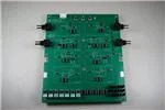
Figure 16 shows the layout of the overview for the TI-PLABS-AMP-EVM board. The board is designed so
that the silkscreen shows the schematic of the key sections of the board. Jumper placement is
incorporated into the silk screen so that circuit configuration is intuitive.
Figure 16. PCB Components Layout
SBOU150A – January 2015 – Revised February 2015
Submit Documentation Feedback
Copyright © 2015, Texas Instruments Incorporated
TI-PLABS-AMP-EVM
13
�Schematic, PCB Layout, and Bill of Materials
4.3
www.ti.com
TI-PLABS-AMP-EVM Bill of Materials
Table 3 lists the bill of materials for the TI-PLABS-AMP-EVM PCB.
Table 3. Bill of Materials
Qty
Designator
Manufacturer
Manufacturer Part
Number
Digikey Part Number
2
C20, C21
2.2nF
TDK Corporation
C2012C0G1H222J060AA
445-7507-1-ND
20
C1–C4, C7–C14,
C16–C19, C23,
C24, C26, C28
0.1µF
Kemet
C0805C104K5RACTU
399-1170-1-ND
4
C5, C6, C22, C27
1nF, CAP CER 1000PF 50V 5% NP0 0805
Kemet
C0805C102J5GACTU
399-1136-2-ND
1
C15
150pF
Kemet
C0805C151K5RACTU
399-9176-1-ND
2
C30, C31
CAP, TANT, 10µF, 20V, ±20%, 1 Ω, 3528-21 SMD
AVX
TPSB106M020R1000
478-4087-1-ND
1
C25
3.9nF, CAP CER 3900PF 50V 5% C0G 0805
TDK Corporation
C2012C0G1H392J060AA
445-7510-2-ND
1
C29
2nF, CAP CER 2000PF 50V 5% NP0 0805
Murata Electronics North America
GRM2165C1H202JA01D
490-1627-1-ND
2
D1, D2
Diode, TVS, Uni, 28V, 1500W, SMC
Diodes Inc
SMCJ28A-13-F
SMCJ28A-FDICT-ND
3
GND, V+, V-
Standard Banana Jack, Uninsulated, 5.5mm
Keystone
575-4
575-4K-ND
8
H1–H8
STANDOFF HEX 4-40THR ALUM 1/2 "L
Keystone
2203
2203K-ND
8
H1–H8
MACHINE SCREW PAN PHILLIPS 4-40
B&F Fastener Supply
PMSSS 440 0025 PH
H703-ND
1
J4
2.5 WTB HEADER RA W/KINK 6CKT
Molex
534260610
WM3425-ND
1
J4-A
2.5MM CRIMP HOUSING POS LOCK 6CI
Molex
511030600
WM9191-ND
6
J4-1–J4-6
CONN TERM RCPT 22-28AWG CRIMP
Molex
503518000
WM3320CT-ND
49
Jumpers all
CONN HEADER 2POS 0.100" SGL GOLD
Samtec
TSW-102-07-G-S
SAM1029-02-ND
9
R2, R3, R5,
R11–R14, R25,
R26
RES 1kΩ 1/8W 1% 0805 SMD
Yageo
RC0805FR-071KL
311-1.00KCRCT-ND
11
R27–R37
RES 100 Ω 1/8W 1% 0805 SMD
Yageo
RC0805FR-07100RL
311-100CRCT-ND
2
R4, R38
RES 10kΩM 1/8W 1% 0805 SMD
Yageo
RC0805FR-0710KL
311-10.0KCRCT-ND
3
R6, R9, R10
RES 20kΩ 1/8W 1% 0805 SMD
Yageo
RC0805FR-0720KL
311-20.0KCRCT-ND
3
R1, R7, R8
RES 100kΩ 1/8W 1% 0805 SMD
Yageo
RC0805FR-07100KL
311-100KCRCT-ND
2
R15, R16
RES 4.99kΩ 1/8W 1% 0805 SMD
Yageo
RC0805FR-074K99L
311-4.99KCRCT-ND
2
R18, R19
RES 787 Ω 1/8W 1% 0805 SMD
Yageo
RC0805FR-07787RL
311-787CRCT-ND
1
R17
RES 78.7kΩ 1/8W 1% 0805 SMD
Yageo
RC0805FR-0778K7L
311-78.7KCRCT-ND
4
R20–R24
RES 2.26kΩ 1/8W 1% 0805 SMD
Panasonic Electronic Components
ERJ-6ENF2261V
P2.26KCTR-ND
1
R22
RES 1.13kΩ 1/8W 1% 0805 SMD
Panasonic Electronic Components
ERJ-6ENF1131V
P1.13KCCT-ND
3
TP1, TP4, TP5
TEST POINT PC COMPACT 0.063"D RED
Keystone
5005
5005K-ND
3
TP2, TP6, TP7
TEST POINT PC COMPACT 0.063"D BLK
Keystone
5006
5006K-ND
1
TP3
TEST POINT PC COMPACT 0.063"D YLW
Keystone
5009
5009K-ND
22
U1–U18,
U21–U24
IC SOCKET 8PIN MS TIN/TIN 0.300
Mill-Max
110-44-308-41-001000
ED90048-ND
4
Vin1, Vin2, Vout1,
Vout2
CONN BNC JACK R/A 50 Ω PCB
TE Connectivity
1-1634612-0
A97555-ND
20
14
Description
Shunt, LP W/Handle 2 pos
TE Connectivity
881545-2
A26242-ND
1
N/A
HOOK-UP STRND 24AWG RED 100'
General Cable/Carol Brand
C2015A.12.03
C2015R-100-ND
1
N/A
HOOK-UP STRND 24AWG BLACK 100'
General Cable/Carol Brand
C2015A.12.01
C2015B-100-ND
1
N/A
HOOK-UP STRND 24AWG YELLOW 100'
General Cable/Carol Brand
C2015A.12.05
C2015Y-100-ND
7
N/A
DIP Adapter boards, assembled and labeled as per
DIP Adapter build files
N/A
N/A
N/A
3
N/A
Terminal Strip, 32 position
Samtec
TS-132-G-AA
N/A
2
N/A
IC, OPAMP 8-SOIC
Texas Instruments
OPA211AIDR
2
N/A
IC, OPAMP 8-SOIC
Texas Instruments
OPA188AIDR
1
N/A
IC, OPAMP 8-SOIC
Texas Instruments
OPA277UA
TI-PLABS-AMP-EVM
SBOU150A – January 2015 – Revised February 2015
Submit Documentation Feedback
Copyright © 2015, Texas Instruments Incorporated
�Revision History
www.ti.com
Revision History
Changes from Original (January 2015) to A Revision .................................................................................................... Page
•
Changed Precision-Labs-EVM to TI-PLABS-AMP-EVM throughout document ................................................... 1
NOTE: Page numbers for previous revisions may differ from page numbers in the current version.
SBOU150A – January 2015 – Revised February 2015
Submit Documentation Feedback
Copyright © 2015, Texas Instruments Incorporated
Revision History
15
�IMPORTANT NOTICE FOR TI DESIGN INFORMATION AND RESOURCES
Texas Instruments Incorporated (‘TI”) technical, application or other design advice, services or information, including, but not limited to,
reference designs and materials relating to evaluation modules, (collectively, “TI Resources”) are intended to assist designers who are
developing applications that incorporate TI products; by downloading, accessing or using any particular TI Resource in any way, you
(individually or, if you are acting on behalf of a company, your company) agree to use it solely for this purpose and subject to the terms of
this Notice.
TI’s provision of TI Resources does not expand or otherwise alter TI’s applicable published warranties or warranty disclaimers for TI
products, and no additional obligations or liabilities arise from TI providing such TI Resources. TI reserves the right to make corrections,
enhancements, improvements and other changes to its TI Resources.
You understand and agree that you remain responsible for using your independent analysis, evaluation and judgment in designing your
applications and that you have full and exclusive responsibility to assure the safety of your applications and compliance of your applications
(and of all TI products used in or for your applications) with all applicable regulations, laws and other applicable requirements. You
represent that, with respect to your applications, you have all the necessary expertise to create and implement safeguards that (1)
anticipate dangerous consequences of failures, (2) monitor failures and their consequences, and (3) lessen the likelihood of failures that
might cause harm and take appropriate actions. You agree that prior to using or distributing any applications that include TI products, you
will thoroughly test such applications and the functionality of such TI products as used in such applications. TI has not conducted any
testing other than that specifically described in the published documentation for a particular TI Resource.
You are authorized to use, copy and modify any individual TI Resource only in connection with the development of applications that include
the TI product(s) identified in such TI Resource. NO OTHER LICENSE, EXPRESS OR IMPLIED, BY ESTOPPEL OR OTHERWISE TO
ANY OTHER TI INTELLECTUAL PROPERTY RIGHT, AND NO LICENSE TO ANY TECHNOLOGY OR INTELLECTUAL PROPERTY
RIGHT OF TI OR ANY THIRD PARTY IS GRANTED HEREIN, including but not limited to any patent right, copyright, mask work right, or
other intellectual property right relating to any combination, machine, or process in which TI products or services are used. Information
regarding or referencing third-party products or services does not constitute a license to use such products or services, or a warranty or
endorsement thereof. Use of TI Resources may require a license from a third party under the patents or other intellectual property of the
third party, or a license from TI under the patents or other intellectual property of TI.
TI RESOURCES ARE PROVIDED “AS IS” AND WITH ALL FAULTS. TI DISCLAIMS ALL OTHER WARRANTIES OR
REPRESENTATIONS, EXPRESS OR IMPLIED, REGARDING TI RESOURCES OR USE THEREOF, INCLUDING BUT NOT LIMITED TO
ACCURACY OR COMPLETENESS, TITLE, ANY EPIDEMIC FAILURE WARRANTY AND ANY IMPLIED WARRANTIES OF
MERCHANTABILITY, FITNESS FOR A PARTICULAR PURPOSE, AND NON-INFRINGEMENT OF ANY THIRD PARTY INTELLECTUAL
PROPERTY RIGHTS.
TI SHALL NOT BE LIABLE FOR AND SHALL NOT DEFEND OR INDEMNIFY YOU AGAINST ANY CLAIM, INCLUDING BUT NOT
LIMITED TO ANY INFRINGEMENT CLAIM THAT RELATES TO OR IS BASED ON ANY COMBINATION OF PRODUCTS EVEN IF
DESCRIBED IN TI RESOURCES OR OTHERWISE. IN NO EVENT SHALL TI BE LIABLE FOR ANY ACTUAL, DIRECT, SPECIAL,
COLLATERAL, INDIRECT, PUNITIVE, INCIDENTAL, CONSEQUENTIAL OR EXEMPLARY DAMAGES IN CONNECTION WITH OR
ARISING OUT OF TI RESOURCES OR USE THEREOF, AND REGARDLESS OF WHETHER TI HAS BEEN ADVISED OF THE
POSSIBILITY OF SUCH DAMAGES.
You agree to fully indemnify TI and its representatives against any damages, costs, losses, and/or liabilities arising out of your noncompliance with the terms and provisions of this Notice.
This Notice applies to TI Resources. Additional terms apply to the use and purchase of certain types of materials, TI products and services.
These include; without limitation, TI’s standard terms for semiconductor products http://www.ti.com/sc/docs/stdterms.htm), evaluation
modules, and samples (http://www.ti.com/sc/docs/sampterms.htm).
Mailing Address: Texas Instruments, Post Office Box 655303, Dallas, Texas 75265
Copyright © 2017, Texas Instruments Incorporated
�


 工商网监
湘ICP备2023018690号
工商网监
湘ICP备2023018690号