TLK10081
www.ti.com
SLLSEE9 – NOVEMBER 2013
10Gbps 1-8 CHANNEL MULTI-RATE SERIAL LINK AGGREGATOR
Check for Samples: TLK10081
1 INTRODUCTION
1.1
Features
1
• Automatic Digital Multiplexing/De-Multiplexing
of 1 to 8 Independent Lower Speed Gigabit
Serial Lines into a Single Higher Speed Gigabit
Serial Line with Extensive Media Transmission
Capabilities.
• 1~8 x (0.25 to 1.25 Gbps) to 1 x (2 to 10 Gbps)
Multiplexing
• 1 x (0.5 to 2.5 Gbps) to 1 x (0.5 to 2.5 Gbps)
• Dynamic Port Aggregation Supported
• Programmable High Speed Redundant
Switching
• Wide Data Rate Range for Multiple Application
Support
• Transmit De-Emphasis and Adaptive Receiver
Equalization on Both Low Speed and High
Speed Sides
• MDIO Clause 22 control interface
• 8B/10B ENDEC Coding Support
1.2
•
•
•
•
•
•
•
•
•
•
•
•
Raw (Unencoded) Data Support
Core Supply 1V; I/O: 1.5V/1.8V
Superior Signal Integrity Performance
Low Power Operation: < 800 mW per channel
(typ)
Rate Matching Support (For compatible data
protocols like GE PCS)
Full Non-Blocking Receiver Crosspoint
Mapping Capability
Flexible Clocking
Multi Drive Capability (SFP+, backplane, cable)
Support for Programmable High Speed Lane
Alignment Characters
Support for Programmable HS/LS 10-Bit
Alignment Characters
Wide Range of Built-in Test Patterns
144-pin, 13mmx13mm FCBGA Package
Applications
• Gigabit Serial Link Aggregation
• Communications System Backplanes
spacing
• Machine Vision
• Video/Image Data Processing
1.25GBPS
ASP 1
1.25GBPS
1.25GBPS
1.25GBPS
ASP 2
1.25GBPS
1.25GBPS
1.25GBPS
ASP 3
1.25GBPS
1.25GBPS
ASP 4
1.25GBPS
1.25GBPS
ASP 5
1.25GBPS
1.25GBPS
ASP 6
1.25GBPS
1.25GBPS
ASP 7
1.25GBPS
1.25GBPS
ASP 8
1.25GBPS
1.25GBPS
1.25GBPS
1.25GBPS
ASP 9
1.25GBPS
1.25GBPS
ASP 10
1.25GBPS
1.25GBPS
ASP 11
1.25GBPS
1.25GBPS
ASP 12
1.25GBPS
1.25GBPS
ASP 13
1.25GBPS
1.25GBPS
ASP 14
1.25GBPS
1.25GBPS
ASP 15
1.25GBPS
1.25GBPS
ASP 16
1.25GBPS
1.25GBPS
1.25GBPS
1.25GBPS
EQ
Buffer
1.25GBPS
Backplane
Optical
1.25GBPS
X PT
1.25GBPS
1.25GBPS
1.25GBPS
1.25GBPS
1.25GBPS
1.25GBPS
1.25GBPS
ASP 9
ASP 1
ASP 2
ASP 10
BACKPLANE
OPTICAL
ASP 11
ASP 3
ASP 4
TLK10081
ASP 5
10GBPS
10GBPS
ASP 6
10G
B
10G PS
BPS
ASP 7
ASP 8
ASP 12
10GBPS
10GBPS
Optional
FANOUT or
REDUNDANT
TLK10081
ASP 13
ASP 14
ASP 15
TLK10081
ASP 16
1
Please be aware that an important notice concerning availability, standard warranty, and use in critical applications of
Texas Instruments semiconductor products and disclaimers thereto appears at the end of this data sheet.
PRODUCTION DATA information is current as of publication date. Products conform to
specifications per the terms of the Texas Instruments standard warranty. Production
processing does not necessarily include testing of all parameters.
Copyright © 2013, Texas Instruments Incorporated
�TLK10081
SLLSEE9 – NOVEMBER 2013
1.3
www.ti.com
Description
The TLK10081 is a multi-rate link aggregator intended for use in high-speed bi-directional point-to-point
data transmission systems. The device allows for a reduction in the number of physical links required for a
certain data throughput by multiplexing multiple lower-rate serial links into higher-rate serial links.
The TLK10081 has a low-speed interface which can accommodate one to eight bidirectional serial links
running at rates from 250 Mbps to 1.25 Gbps (maximum of 10 Gbps total throughput). The device’s high
speed interfaces can operate at rates from 1 Gbps to 10 Gbps. The high speed interface is designed to
run at 8 x the low speed serial rate regardless of the number of lanes connected. Filler data will be placed
on any unused lanes in order to keep the interleaved lane ordering constant. This allows for low speed
lanes to be hot swapped during normal operation without requiring a change in configuration.
A 1:1 mode is also supported for data rates ranging from 0.5 Gbps to 2.5 Gbps, whereby both low speed
and high speed are rate matched. The TX and RX datapaths are also independent, so TX may operate in
8:1 mode while RX operates in 1:1 mode. This independence is restricted to using the same low speed
line rate. For example, the TX can operate at 8 x 1.25 Gbps while RX operates at 1 x 1.25 Gbps.
The individual Low Speed lanes may also operate at independent rates in byte interleave mode, provided
they are operating at integer multiples. The High Speed line rate must be configured based on the fastest
Low Speed line rate.
The device has multiple interleaving/de-interleaving schemes that may be used depending on the data
type. These schemes allow for the low speed lane ordering to be recovered after the lanes are transmitted
over a single high-speed link. There is also a programmable scrambling/de-scrambling function available
to help ensure that the high-speed data has suitable properties for transmission (i.e., sufficient transition
density for clock recovery and DC balance over time) even for non-ideal input data.
The TLK10081 has the ability to perform lane alignment on 2, 3, or 4 lanes with up to four bytes of lane
de-skew.
Both the low speed and high speed side interfaces (transmitters and receivers) use CML signaling with
integrated termination resistors and feature programmable transmitter de-emphasis levels and adaptive
receive equalization to help compensate for media impairments at higher frequencies. The device’s serial
transceivers used are capable of interfacing to optical modules as well as higher-loss connections such as
PCB backplanes and controlled-impedance copper cabling.
To aid in system synchronization, the TLK10081 is capable of extracting clocking information from the
serial input data streams and outputting a recovered clock signal. This recovered clock can be input to a
jitter cleaner in order to provide a synchronized system clock. The device also has two reference clock
input ports and a flexible internal PLL, allowing for various serial rates to be supported with a single
reference clock input frequency.
The device has various built-in self-test features to aid with system validation and debugging. Among
these are pattern generation and verification on all serial lanes as well as internal data loopback paths.
2
INTRODUCTION
Copyright © 2013, Texas Instruments Incorporated
Submit Documentation Feedback
Product Folder Links: TLK10081
�TLK10081
www.ti.com
SLLSEE9 – NOVEMBER 2013
2 PHYSICAL CHARACTERISTICS
2.1
Block Diagram
A simplified block diagram of the TLK10081 device for 8:1 mode is shown in Figure 2-1 and Figure 2-2.
This low-power transceiver consists of two serializer/deserializer (SERDES) blocks, one on the low speed
side and the other on the high speed side. The core logic block that lies between the two SERDES blocks
carries out all the logic functions including test pattern generation and verification.
The TLK10081 provides a management data input/output (MDIO) control interface as well as a JTAG
interface for device configuration, control, and monitoring. Detailed descriptions of the TLK10081 pin
functions are provided in Figure 2-1.
TLK10081 TX
Serdes
1:10
CH
SYNC
Serdes
1:10
Serdes
1:10
M
U
X
FIFO
CH
SYNC
Serdes
1:10
CH
SYNC
CH
SYNC
CH
SYNC
M
U
X
0
8b/10b
8b/10b
M
U
X
M
U
X
M
U
X
FIFO
8b/10b
M
U
X
FIFO
M
U
X
SCR
M
U
X
8b/10b
1
8b/10b
M
U
X
Serdes
1:10
Serdes
1:10
CH
SYNC
FIFO
8b/10b
Serdes
1:20
CH
SYNC
M
U
X
Serdes
1:20
Serdes
1:10
CH
SYNC
Serdes
1:10
Read
Controller
M
U
X
FIFO
M
U
X
FIFO
LN0
MARK
2
8b/10b
8b/10b
M
U
X
FIFO
3
M
U
X
8b/10b
M
U
X
SCR
FIFO
8b/10b
Figure 2-1. A Simplified Block Diagram of the TLK10081 (TX)
PHYSICAL CHARACTERISTICS
Copyright © 2013, Texas Instruments Incorporated
Submit Documentation Feedback
Product Folder Links: TLK10081
3
�TLK10081
SLLSEE9 – NOVEMBER 2013
www.ti.com
Serdes
1:10
Serdes
1:10
M
U
X
Serdes
1:10
M
U
X
M
U
X
M
U
X
8b/10b
SKEW
FIFO
8b/10b
SKEW
FIFO
8b/10b
SKEW
FIFO
8b/10b
8b/10b
SKEW
FIFO
D
E
M
U
X
8b/10b
SKEW
MARKER
REPLACE
LANE
ORDERING
Ch_sync
JOG
M
U
X
FIFO
M
U
X
Serdes
1:10
Serdes
1:10
M
U
X
Serdes
1:10
DSCR
M
U
X
M
U
X
8b/10b
SKEW
FIFO
8b/10b
SKEW
FIFO
8b/10b
SKEW
FIFO
M
U
X
Serdes
1:20
Serdes
1:10
M
U
X
Serdes
1:10
TLK10081 RX
Figure 2-2. A Simplified Block Diagram of the TLK10081 (RX)
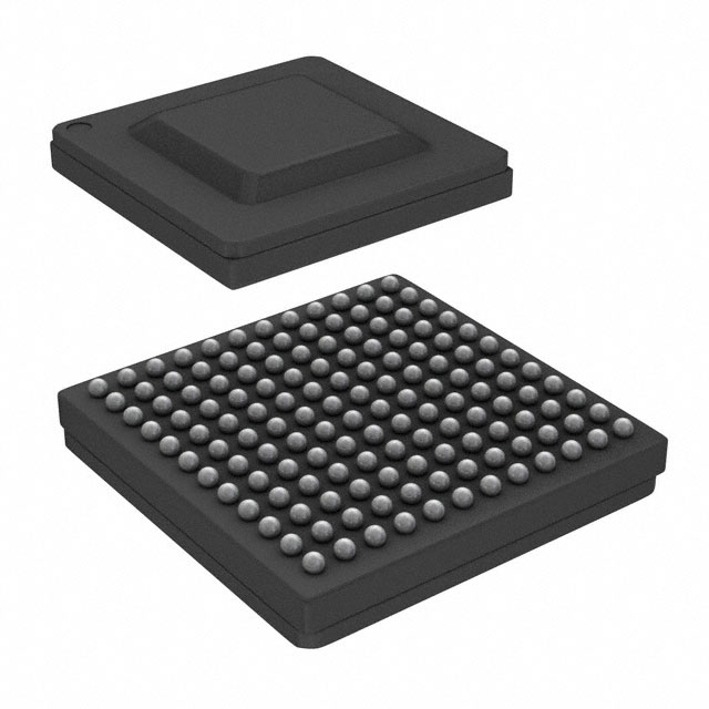
2.2
Package
A 13-mm x 13-mm, 144-pin PBGA package with a ball pitch of 1 mm is used. The device pin-out is as
shown in Figure 2-3 and is described in detail in Table 2-1 and Table 2-2.
Figure 2-3. The Pin-Out of the TLK10081
4
PHYSICAL CHARACTERISTICS
Copyright © 2013, Texas Instruments Incorporated
Submit Documentation Feedback
Product Folder Links: TLK10081
�TLK10081
www.ti.com
2.3
SLLSEE9 – NOVEMBER 2013
Terminal Functions
The details of the terminal functions of the TLK10081 device are provided in Table 2-1 and Table 2-2.
Table 2-1. Pin Description - Signal Pins
TERMINAL
SIGNAL
BGA
DIRECTION
TYPE
SUPPLY
DESCRIPTION
CHANNEL A
HSTXAP
HSTXAN
D12
E12
Output
CML
VDDA_HS
High Speed Transmit Channel A Output. HSTXAP and HSTXAN comprise the high speed side
transmit direction Channel A differential serial output signal. During device reset (RESET_N
asserted low) these pins are driven differential zero. These CML outputs must be AC coupled.
HSRXAP
HSRXAN
B12
A12
Input
CML
VDDA_HS
High Speed Receive Channel A Input. HSRXAP and HSRXAN comprise the high speed side
receive direction Channel A differential serial input signal. These CML input signals must be AC
coupled.
INA[7:0]P/N
M3/M4
L1/M1
K2/L2
H1/J1
D1/E1
B2/C2
A1/B1
A4/A3
Input
CML
VDDA_LS
Low Speed Channel A Inputs. INAP and INAN comprise the low speed side transmit direction
differential input signals. These signals must be AC coupled.
OUTA[7:0]P/N
M7/M6
L6/L5
K5/K4
J3/H3
F3/E3
C4/C5
B5/B6
A6/A7
Output
CML
VDDA_LS
Low Speed Channel A Outputs. OUTAP and OUTAN comprise the low speed side receive
direction differential output signals. During device reset (RESET_N asserted low) these pins are
driven differential zero. These signals must be AC coupled.
LOSA
E9
Output LVCMOS
1.5V/1.8V
VDDO0
40Ω Driver
Channel A Receive Loss Of Signal (LOS) Indicator.
LOSA=0: Signal detected.
LOSA=1: Loss of signal.
Loss of signal detection is based on the input signal level. When HSRXAP/N has a differential
input signal swing of ≤75 mVpp, LOSA will be asserted (if enabled). If the input signal is greater
than 150 mVp-p, LOS will be deasserted. Outside of these ranges, the LOS indication is undefined.
Other functions can be observed on LOSA real-time, configured via MDIO
During device reset (RESET_N asserted low) this pin is driven low. During pin based power down
(PDTRXA_N asserted low), this pin is floating. During register based power down, this pin is
floating.
It is highly recommended that LOSA be brought to an easily accessible point on the application
board (header) in the event that debug is required.
B10
Input
LVCMOS
1.5V/1.8V
VDDO0
Channel A Bit Interleave Lane Rotation Jog.
A toggle of this pin, either from high to low or from low to high, causes a lane rotation of the
HSRXAP/N source data.
GPO0
D9
Output
LVCMOS
1.5V/1.8V
VDDO0
40Ω Driver
Channel A Multi-purpose Status Indicator.
This pin should be left unconnected in the device application.
PDTRXA_N
A8
Input
LVCMOS
1.5V/1.8V
VDDO0
Transceiver Power Down.
When this pin is held low (asserted), the device is placed in power down mode. When deasserted,
the device operates normally. After deassertion, a software data path reset should be issued
through the MDIO interface.
RXCTRL_0
CHANNEL B (High Speed Interface Only)
HSTXBP
HSTXBN
K12
L12
Output
CML
VDDA_HS
Serial Transmit Channel B Output. HSTXBP and HSTXBN comprise the high speed side
transmit direction Channel B differential serial output signal. During device reset (RESET_N
asserted low) these pins are driven differential zero. These CML outputs must be AC coupled.
HSRXBP
HSRXBN
H12
G12
Input
CML
VDDA_HS
Serial Receive Channel B Input. HSRXBP and HSRXBN comprise the high speed side receive
direction Channel B differential serial input signal. These CML input signals must be AC coupled.
PHYSICAL CHARACTERISTICS
Copyright © 2013, Texas Instruments Incorporated
Submit Documentation Feedback
Product Folder Links: TLK10081
5
�TLK10081
SLLSEE9 – NOVEMBER 2013
www.ti.com
Table 2-1. Pin Description - Signal Pins (continued)
TERMINAL
SIGNAL
LOSB
BGA
K8
DIRECTION
TYPE
SUPPLY
Output
LVCMOS
1.5V/1.8V
VDDO1
40Ω Driver
DESCRIPTION
Channel B Receive Loss of Signal (LOS) Indicator.
LOSB=0: Signal detected.
LOSB=1: Loss of signal.
Loss of signal detection is based on the input signal level. When HSRXBP/N has a differential
input signal swing of ≤75 mVpp, LOSB will be asserted (if enabled). If the input signal is greater
than 150 mVp-p, LOS will be deasserted. Outside of these ranges, the LOS indication is
undefined.
Other functions can be observed on LOSB real-time, configured via MDIO.
During device reset (RESET_N asserted low) this pin is driven low. During pin based power down
(PDTRXB_N asserted low), this pin is floating. During register based power down, this pin is
floating.
It is highly recommended that LOSB be brought to an easily accessible point on the application
board (header) in the event that debug is required.
L8
Input
LVCMOS
1.5V/1.8V
VDDO1
Channel B Bit Interleave Lane Rotation Jog.
A toggle of this pin, either from high to low or from low to high, causes a lane rotation of the
HSRXBP/N source data.
GPO1
H9
Output
LVCMOS
1.5V/1.8V
VDDO1
40Ω Driver
Channel B General Purpose Output.
This pin should be left unconnected in the device application.
PDTRXB_N
J4
Input
LVCMOS
1.5V/1.8V
VDDO1
Transceiver Power Down. When this pin is held low (asserted), Channel B is placed in power
down mode. When deasserted, Channel B operates normally. After deassertion, a software data
path reset should be issued through the MDIO interface.
RXCTRL_1
REFERENCE CLOCKS AND CONTROL AND MONITORING SIGNALS
REFCLK0P/N
M10 / M11
Input
LVDS/LVPECL
DVDD
Reference Clock Input Zero. This differential input is a clock signal used as a reference to one or
both channels.The reference clock selection is done through MDIO or REFCLKA_SEL and
REFCLKB_SEL pins. This input signal must be AC coupled. If unused, REFCLK0P/N should be
pulled down to GND through a shared 100 ohm resistor.
REFCLK1P/N
K9 / K10
Input
LVDS/LVPECL
DVDD
Reference Clock Input One. This differential input is a clock signal used as a reference to one or
both channels. The reference clock selection is done through MDIO. This input signal must be AC
coupled. If unused, REFCLK1P/N should be pulled down to GND through a shared 100 ohm
resistor.
REFCLK_SEL
H10
Input
LVCMOS
1.5V/1.8V
VDDO0
Reference Clock Select. This input, when low, selects REFCLK0P/N as the clock reference to
Channel A/B SERDES. When high, REFCLK1P/N is selected as the clock reference to Channel
A/B SERDES. If software control is desired, this input signal should be tied low. Default reference
clock for Channel A/B is REFCLK0P/N.
Channel A/B Output Clock. By default, this output is enabled and outputs the high speed side
Channel A recovered byte clock (high speed line rate divided by 20). Optionally it can be
configured to output the VCO clock divided by 2. Additional MDIO-selectable divide ratios of 1, 2,
4, 5, 8, 10, 16, 20, and 25 are available. See Figure 5-1.
CLKOUTAP/N
CLKOUTBP/N
C9/C10
A9/A10
Output
CML
DVDD
These CML outputs must be AC coupled.
During device reset (RESET_N asserted low) these pins are driven differential zero.
During pin based power down (PDTRXA_N and PDTRXB_N asserted low), these pins are
floating.
During register based power down, these pins are floating.
PRBSEN
B9
Input
LVCMOS
1.5V/1.8V
VDDO0
Enable PRBS: When this pin is asserted high, the internal PRBS generator and verifier circuits
are enabled on both transmit and receive data paths on high speed and low speed sides of both
channels.
This signal is logically OR’d with MDIO register bits A.13:12, and B.13:12.
PRBS 231-1 is selected by default, and can be changed through MDIO.
PRBS_PASS
J9
Output
LVCMOS
/1.8V
VDDO1
40Ω Driver
Receive PRBS Error Free (Pass) Indicator.
When PRBS test is enabled (PRBSEN=1):
PRBS_PASS=1 indicates that PRBS pattern reception is error free.
PRBS_PASS=0 indicates that a PRBS error is detected. The channel, high speed or low speed
side, and lane (for low speed side) that this signal refers to is chosen through MDIO register bits
0.3:0.
During device reset (RESET_N asserted low) this pin is driven low.
During pin based power down (PDTRXA_N and PDTRXB_N asserted low), this pin is floating.
During register based power down, this pin is floating.
It is highly recommended that PRBS_PASS be brought to easily accessible point on the
application board (header), in the event that debug is required.
6
PHYSICAL CHARACTERISTICS
Copyright © 2013, Texas Instruments Incorporated
Submit Documentation Feedback
Product Folder Links: TLK10081
�TLK10081
www.ti.com
SLLSEE9 – NOVEMBER 2013
Table 2-1. Pin Description - Signal Pins (continued)
TERMINAL
SIGNAL
BGA
DIRECTION
TYPE
SUPPLY
PRTAD[4:0]
M8
J6
L9
G9
E10
Input
LVCMOS
1.5V/1.8V
VDDO[1:0]
RESET_N
H5
Input
LVCMOS
1.5V/1.8V
VDDO01
J8
Input
LVCMOS
with Hysteresis
1.5V/1.8V
VDDO1
MDC
J7
Input/Output
LVCMOS
1.5V/1.8V
VDDO1
25Ω Driver
TDI
C8
Input LVCMOS
1.5V/1.8V VDDO0
(Internal Pullup)
TDO
D6
MDIO
Output LVCMOS
1.5V/1.8V VDDO0
50Ω Driver
DESCRIPTION
MDIO Port Address. Used to select the MDIO port address.
The TLK10081 will respond if the port address field on MDIO protocol (PA[4:0]) matches
PRTAD[4:0].)
Low True Device Reset. RESET_N must be held asserted (low logic level) for at least 10µs after
device power stabilization.
MDIO Clock Input. Clock input for the Clause 22 MDIO interface.
Note that an external pullup is generally not required on MDC.
MDIO Data I/O. MDIO interface data input/output signal for the Clause 22 MDIO interface. This
signal must be externally pulled up to VDDO using a 2kΩ resistor.
During device reset (RESET_N asserted low) this pin is floating. During software initiated power
down the management interface remains active for control register writes and reads. Certain
status bits are not deterministic as their generating clock source may be disabled as a result of
asserting either power down input signal. During pin based power down (PDTRXA_N and
PDTRXB_N asserted low), this pin is floating. During register based power down (1.15 asserted
high both channels), this pin is driven normally.
JTAG Input Data. TDI is used to serially shift test data and test instructions into the device during
the operation of the test port. In system applications where JTAG is not implemented, this input
signal may be left floating.
During pin based power down (PDTRXA_N and PDTRXB_N asserted low), this pin is not pulled
up. During register based power down, (1.15 asserted high both channels), this pin is pulled up
normally.
JTAG Output Data. TDO is used to serially shift test data and test instructions out of the device
during the operation of the test port. When the test port is not in use, TDO is in a high impedance
state.
During device reset (RESET_N asserted low) this pin is floating. During pin based power down
(PDTRXA_N and PDTRXB_N asserted low), this pin is not pulled up. During register based power
down, (1.15 asserted high both channels), this pin is pulled up normally.
JTAG Mode Select. TMS is used to control the state of the internal test-port controller. In system
applications where JTAG is not implemented, this input signal can be left unconnected.
During pin based power down (PDTRXA_N and PDTRXB_N asserted low), this pin is not pulled
up. During register based power down, (1.15 aserted high both channels), this pin is pulled up
normally.
TMS
B8
Input LVCMOS
1.5V/1.8V VDDO0
(Internal Pullup)
TCK
D8
Input LVCMOS
with Hysteresis
1.5V/1.8V VDDO0
JTAG Clock. TCK is used to clock state information and test data into and out of the device
during boundary scan operation. In system applications where JTAG is not implemented, this
input signal should be grounded.
TRST_N
E5
Input LVCMOS
1.5V/1.8V VDDO0
(Internal Pulldown)
JTAG Test Reset. TRST_N is used to reset the JTAG logic into system operational mode. This
input can be left unconnected in the application and is pulled down internally, disabling the JTAG
circuitry. If JTAG is implemented on the application board, this signal should be deasserted (high)
during JTAG system testing, and otherwise asserted (low) during normal operation mode.
During pin based power down (PDTRXA_N and PDTRXB_N asserted low), this pin is not pulled
down. During register based power down (1.15 asserted high both channels), this pin is pulled
down normally.
TESTEN
L10
Input LVCMOS
1.5V/1.8V VDDO1
Test Enable. This signal is used during the device manufacturing process. It should be grounded
through a resistor in the device application board.
GPI0
J10
Input LVCMOS
1.5V/1.8V VDDO1
General Purpose Input Zero. This signal is used during the device manufacturing process. It
should be grounded through a resistor on the device application board.
GPI1
M9
Input LVCMOS
1.5V/1.8V VDDO1
General Purpose Input One. This signal is used during the device manufacturing process. It
should be grounded through a resistor on the device application board.
AMUXA
C11
Analog I/O
SERDES Channel A Analog Testability I/O. This signal is used during the device manufacturing
process. It should be left unconnected in the device application.
AMUXB
D4
Analog I/O
SERDES Channel B Analog Testability I/O. This signal is used during the device manufacturing
process. It should be left unconnected in the device application.
PHYSICAL CHARACTERISTICS
Copyright © 2013, Texas Instruments Incorporated
Submit Documentation Feedback
Product Folder Links: TLK10081
7
�TLK10081
SLLSEE9 – NOVEMBER 2013
www.ti.com
Table 2-2. Pin Description - Power Pins
TERMINAL
SIGNAL
VDDA_LS/HS
BGA
D2, F2, G2, J2, F11, G10
TYPE
DESCRIPTION
Power
SERDES Analog Power.
VDDA_LS and VDDA_HS provide supply voltage for the analog circuits on the
low-speed and high-speed sides respectively. 1.0V nominal. Can be tied
together on the application board.
VDDT_LS/HS
F4, G4, F9
Power
SERDES Analog Power.
VDDT_LS and VDDT_HS provide termination and supply voltage for the analog
circuits on the low-speed and high-speed sides respectively. 1.0V nominal. Can
be tied together on the application board.
VDDD
E6, E8, F6, H6, H8
Power
SERDES Digital Power.
VDDD provides supply voltage for the digital circuits internal to the SERDES.
1.0V nominal.
DVDD
E7, F7, G6, G8, H7
Power
Digital Core Power.
DVDD provides supply voltage to the digital core. 1.0V nominal.
VDDRA_LS,
VDDRB_LS
C3, K3
Power
SERDES Analog Regulator Power.
VDDRA_LS and VDDRB_LS provide supply voltage for the internal PLL
regulator for the low speed side. 1.5V or 1.8V nominal.
VDDRA_HS
E11
Power
SERDES Analog Regulator Power.
VDDRA_HS provides supply voltage for the internal PLL regulator for high
speed Channel A. 1.5V or 1.8V nominal.
VDDRB_HS
J11
Power
SERDES Analog Regulator Power
VDDRB_HS provides supply voltage for the internal PLL regulator for high
speed Channel B. 1.5V or 1.8V nominal.
VDDO[1:0]
K7, C7
Power
LVCMOS I/O Power.
VDDO0 and VDDO1 provide supply voltage for the LVCMOS inputs and
outputs. 1.5V or 1.8V nominal. Can be tied together on the application board.
VPP
D7
Power
Factory Program Voltage.
Used during device manufacturing. The application must connect this power
supply directly to DVDD.
VSS
A2, A5, A11, B3, B4, B7,
B11, C1, C6, C12, D3,
D5, D10, D11, E2, E4, F1,
F5, F8, F10, F12, G1, G3,
G5, G7, G11, H2, H4,
H11, J5, J12, K1, K6,
K11, L3, L4, L7, L11, M2,
M5, M12
Ground
Ground.
Common analog and digital ground.
8
PHYSICAL CHARACTERISTICS
Copyright © 2013, Texas Instruments Incorporated
Submit Documentation Feedback
Product Folder Links: TLK10081
�TLK10081
www.ti.com
SLLSEE9 – NOVEMBER 2013
3 FUNCTIONAL DESCRIPTION
The TLK10081 allows for high-speed interleaving/de-interleaving of 1 to 8 serial data streams to aggregate
them into a single physical link. The data processing required to support this functionality is detailed in the
following subsections.
3.1
Transmit (Interleaving) Direction
Two configurations for TLK10081 transmit data path with the device configured to operate in the normal
transceiver (mission) mode are shown in Figure 3-1 and Figure 3-2.
In the transmit direction, the lower-rate serial lanes to be interleaved are first received by a deserializer
(one per lane) capable of resolving data at up to 5 Gbps. This deserialized data can be optionally aligned
to 10-bit word boundaries (based on a user-defined 10-bit alignment character) and optionally 8b/10b
decoded. If these functions are not relevant to the data being received, they can be bypassed. The
received data on each is input to a FIFO in order to compensate for phase differences between the low
speed serial links and the high speed side of the chip. This FIFO is also capable of clock tolerance
compensation if needed.
The high speed side can then aggregate the data in one of two ways – (1) word interleaving or (2) bit
interleaving. If word interleaving is chosen, the low speed data streams are interleaved in a round-robin
fashion 10 bits at a time. If bit interleaving is chosen, the interleaving is performed on a bit-by-bit basis. In
either case, provisions need to be taken so that the far-end receiver is able to correctly identify the lane
assignments. This is handled by the device’s lane ordering logic, described in Section 3.3.
The high-speed aggregate data stream can then be optionally 8b/10b encoded and optionally scrambled
by a polynomial scrambling function. These functions provide different ways of ensuring the high speed
serial output can be received properly by a device at the other end of the link (by increasing the transition
density and by giving a more even distribution of high and low levels). Note that if both the encoding and
scrambling functions are used, the user can determine whether to first encode the data and then scramble
or to first scramble the data and then encode. If the latter option is chosen, scrambling is not performed on
control codes (Kx.x). The resulting data is then output by a serializer capable of data rates up to 10 Gbps.
FUNCTIONAL DESCRIPTION
Copyright © 2013, Texas Instruments Incorporated
Submit Documentation Feedback
Product Folder Links: TLK10081
9
�TLK10081
SLLSEE9 – NOVEMBER 2013
www.ti.com
TLK10081 TX
Serdes
1:10
CH
SYNC
Serdes
1:10
M
U
X
FIFO
M
U
X
FIFO
8b/10b
M
U
X
M
U
X
8b/10b
M
U
X
FIFO
M
U
X
SCR
M
U
X
8b/10b
1
8b/10b
M
U
X
M
U
X
FIFO
M
U
X
FIFO
LN0
MARK
2
Serdes
1:10
8b/10b
CH
SYNC
8b/10b
Serdes
1:10
CH
SYNC
M
U
X
0
8b/10b
CH
SYNC
8b/10b
Serdes
1:10
Serdes
1:10
CH
SYNC
FIFO
Serdes
1:20
CH
SYNC
M
U
X
8b/10b
Serdes
1:20
Serdes
1:10
CH
SYNC
Serdes
1:10
Read
Controller
CH
SYNC
M
U
X
FIFO
3
M
U
X
M
U
X
SCR
FIFO
8b/10b
Figure 3-1. Transmit Datapath, 10-Bit Mode
10
FUNCTIONAL DESCRIPTION
Copyright © 2013, Texas Instruments Incorporated
Submit Documentation Feedback
Product Folder Links: TLK10081
�TLK10081
www.ti.com
SLLSEE9 – NOVEMBER 2013
TLK10081 TX
Serdes
1:10
CH
SYNC
Serdes
1:10
Serdes
1:10
M
U
X
FIFO
M
U
X
M
U
X
M
U
X
M
U
X
FIFO
M
U
X
SCR
M
U
X
8b/10b
FIFO
8b/10b
M
U
X
FIFO
M
U
X
FIFO
LN0
MARK
8b/10b
8b/10b
M
U
X
Serdes
1:10
CH
SYNC
M
U
X
8b/10b
M
U
X
CH
SYNC
8b/10b
8b/10b
CH
SYNC
8b/10b
Serdes
1:10
Serdes
1:10
CH
SYNC
FIFO
8b/10b
Serdes
1:20
CH
SYNC
M
U
X
Serdes
1:20
Serdes
1:10
CH
SYNC
Serdes
1:10
Read
Controlle
r
CH
SYNC
8b/10b
FIFO
M
U
X
M
U
X
SCR
FIFO
Figure 3-2. Transmit Datapath, Raw Serial Data (Bit Interleave)
3.2
Receive (De-Interleaving) Direction
With the device configured to operate in the normal transceiver (mission) mode, the receive data paths are
as shown in Figure 3-2, Receive data path (10-bit mode), and Figure 3-3, Receive data path (raw serial
mode).
In the receive direction, the high speed aggregate stream is received by a deserializer capable of data
rates up to 10 Gbps. The deserialized data is then aligned to 20-bit boundaries by the device’s channel
synchronization logic. This alignment can be based on a user-defined 10-bit alignment code (in the case
of 8b/10b or otherwise 10-bit delineated data) or can be done arbitrarily (for cases where 10-bit delineation
is not meaningful). In either case, the chosen word boundaries can be adjusted manually if necessary to
adjust the bit assignments.
Once the data is aligned, it can be optionally 8b/10b decoded or descrambled as needed before being
input to the device’s receive lane ordering logic (discussed in detail in Section 3.3). After lane assignments
are determined, the de-aggregated serial data streams are input to independent FIFOs in order to absorb
phase variations between the high-speed and low-speed clock domains and to compensate for clock rate
differences if desired.
Each low speed data stream will pass through a programmable skew buffer (in case delays need to be
added to certain lanes in order to meet system-level skew requirements) and optionally 8b/10b encoded
before being output by a serializer capable of rates up to 1.25 Gbps.
FUNCTIONAL DESCRIPTION
Copyright © 2013, Texas Instruments Incorporated
Submit Documentation Feedback
Product Folder Links: TLK10081
11
�TLK10081
SLLSEE9 – NOVEMBER 2013
www.ti.com
Serdes
1:10
Serdes
1:10
M
U
X
Serdes
1:10
M
U
X
M
U
X
M
U
X
8b/10b
SKEW
FIFO
8b/10b
SKEW
FIFO
8b/10b
SKEW
FIFO
8b/10b
SKEW
FIFO
8b/10b
D
E
M
U
X
8b/10b
SKEW
MARKER
REPLACE
LANE
ORDERING
Ch_sync
JOG
M
U
X
FIFO
Serdes
1:10
Serdes
1:10
M
U
X
Serdes
1:10
DSCR
M
U
X
M
U
X
8b/10b
SKEW
FIFO
8b/10b
SKEW
FIFO
8b/10b
SKEW
FIFO
M
U
X
Serdes
1:20
Serdes
1:10
M
U
X
Serdes
1:10
TLK10081 RX
M
U
X
Figure 3-3. Receive Datapath, 10-Bit Mode
Serdes
1:10
Serdes
1:10
M
U
X
Serdes
1:10
M
U
X
M
U
X
M
U
X
8b/10b
SKEW
FIFO
8b/10b
SKEW
FIFO
8b/10b
SKEW
FIFO
8b/10b
SKEW
FIFO
8b/10b
D
E
M
U
X
8b/10b
SKEW
MARKER
REPLACE
LANE
ORDERING
Ch_sync
JOG
M
U
X
FIFO
Serdes
1:10
Serdes
1:10
M
U
X
Serdes
1:10
DSCR
M
U
X
M
U
X
8b/10b
SKEW
FIFO
8b/10b
SKEW
FIFO
8b/10b
SKEW
FIFO
M
U
X
Serdes
1:20
Serdes
1:10
M
U
X
Serdes
1:10
TLK10081 RX
M
U
X
Figure 3-4. Receive Datapath, Raw Serial Data
In 1:1 mode, the receive datapath is similar to 8:1 mode, but does not have a skew buffer or a
programmable descrambler. Lanes 1-7 are not used.
12
FUNCTIONAL DESCRIPTION
Copyright © 2013, Texas Instruments Incorporated
Submit Documentation Feedback
Product Folder Links: TLK10081
�TLK10081
www.ti.com
3.3
SLLSEE9 – NOVEMBER 2013
Lane Ordering
When multiple serial data links are multiplexed into a single physical link, special provisions need to be
taken in order for the original lane assignments to be recovered at the far end of the link. The TLK10081
provides several methods to accomplish this.
3.3.1
Reserved Lane Marker Characters
If the data to be aggregated can be deserialized into 10-bit words, then it is possible to identify certain
reserved codes that can be used to keep track of lane assignments. In the TX direction, the TLK10081
can be configured to identify a programmable “search” character (one that is expected to occur in the data
stream) and replace it with another programmable “replace” character (one that is not expected to occur in
the data stream). In the RX direction, the device can search for this reserved code in the high speed data
it is receiving and use the position of the code in the aggregated data stream to determine the correct lane
assignments. This code can then be replaced with another programmable character before being output
on the low speed side. This allows for the lane marking process to be transparent to systems interfacing to
the TLK10081’s low speed side.
3.3.2
Training Sequence
If it not possible to define reserved lane marking codes (for example, if the low-speed serial data does not
have 10-bit delineation or unused codes), then it is possible to configure the TLK10081 so that lane
ordering is determined at link start-up (prior to normal data transmission). This is accomplished via a
training sequence sent over the high speed link from the transmitting device to the receiving device. Once
the receiver has detected the training sequence and has determined lane ordering (as indicated through
MDIO registers), then the transmitter can transition into normal operation.
3.3.3
Manual Lane Rotation
If the application allows for lane ordering to be determined at a system level instead, the TLK10081
provides a manual method for cycling through the possible lane order rotations. If manual rotation is used,
then the device will iterate through different rotations as controlled by either MDIO registers or the
RXCTRL pins.
3.3.4
Reserved Lane
If fewer than eight low speed lanes are required by the application, one lane can be used to continuously
send lane ordering information. This allows for continual monitoring of lane ordering so that the
assignments can be quickly re-established in the event of a link disruption.
FUNCTIONAL DESCRIPTION
Copyright © 2013, Texas Instruments Incorporated
Submit Documentation Feedback
Product Folder Links: TLK10081
13
�TLK10081
SLLSEE9 – NOVEMBER 2013
www.ti.com
10-Bit Programmable Marker
Replacement
10-Bit Programmable byte
boundary framer
A1
10-Bit Programmable Marker ID
and Replacement
M0
M0
TLK10081 RX
Serdes
1:10
A2
Serdes
1:10
B3
Serdes
1:10
A1
C2
D3
A1
CH
SYNC
FIFO +
Marker
CH
SYNC
FIFO
CH
SYNC
FIFO
CH
SYNC
FIFO
A2
M0
1.25Gbps
B5
B4
B3
B2
B2
1.25Gbps
FIFO
SKEW
A2
A1
A4
FIFO
SKEW
B3
B2
Serdes
10:1
A2
MARKER
REPLACE +
LANE
ORDERING
Serdes
10:1
A3
Serdes
1:10
TLK10081 TX
A4
A1
B5
FIFO
SKEW
C2
C1
FIFO
SKEW
FIFO
A2
A1
A3
A2
A1
1.25Gbps
B3
B3
B2
B2
C2
C2
B4
B3
B2
1.25Gbps
D3
Serdes
1:10
E4
Serdes
1:10
F1
Serdes
1:10
E3
G5
H3
E3
H2
G4
F0
E3
D2
C1
B2
M0
Serdes
1:20
M
U
X
Serdes
1:10
E4
D5
SKEW
E4
E3
E6
FIFO
SKEW
F1
F0
F3
FIFO
SKEW
G5
G4
G7
FIFO
SKEW
H5
D3
10Gbps
D2
Serdes
20:1
E5
D2
C3
C2
C1
1.25Gbps
D2
1.25Gbps
E6
D3
Serdes
1:10
D2
Serdes
1:10
D3
C1
1.25Gbps
C4
Serdes
10:1
D4
C1
Serdes
10:1
D5
C1
Serdes
1:10
C3 C2 C1
2.5Gbps
1.25Gbps
Serdes
1:10
C4
CH
SYNC
E4
CH
SYNC
FIFO
CH
SYNC
FIFO
CH
SYNC
FIFO
CH
SYNC
FIFO
D
E
M
U
X
D2
D4
D3
D2
1.25Gbps
E4
E3
E3
F1
F1
F0
F0
G5
G5
G4
G4
H3
H3
H2
H2
E5
E4
E3
1.25Gbps
F3
F2
F1
F0
F0
1.25Gbps
F2
F1
F0
1.25Gbps
G7
G6
G5
G4
G4
1.25Gbps
G6
G5
G4
1.25Gbps
H5
H4
H3
H2
1.25Gbps
H2
1.25Gbps
Sn
H3
H2
H4
H3
H2
Symbol ± 10 bits
M0
Lane 0 Marker ± 10 bits ± Programmable char identified is replaced with programmable Marker
Figure 3-5. Block Diagram of the Interleave/De-interleave Scheme
3.4
3.4.1
Additional Functionality
1:1 Mode
The TLK10081 also supports a 1:1 mode for data retiming. The data path for this mode is shown below. In
the transmit direction, data is received by the low-speed deserializer on Lane 0 of the selected channel,
aligned to word boundaries (if applicable), 8b/10b decoded (if applicable), input to a phase-correction
FIFO capable of clock tolerance compensation, optionally 8b/10b encoded, and transmitted out the high
speed serial ports. The receive direction operates similarly, but in the opposite direction (eventually
outputting the serial data on low speed Lane 0).
8b/10b
Decoder
FIFO
8b/10b
Encoder
Ch_sync
JOG
Serdes
1:10
Ch_sync
JOG
Serdes
10:1
Serdes
1:10
1:1 Mode TX
Serdes
10:1
1:1 Mode RX
8b/10b
Encoder
FIFO
8b/10b
Decoder
Figure 3-6. 1:1 Mode Datapath
14
FUNCTIONAL DESCRIPTION
Copyright © 2013, Texas Instruments Incorporated
Submit Documentation Feedback
Product Folder Links: TLK10081
�TLK10081
www.ti.com
SLLSEE9 – NOVEMBER 2013
Note that it is possible to operate one direction (transmit or receive) of a particular channel in 1:1 mode
while the other direction operates in 8:1 mode.
3.4.2
Clock Tolerance Compensation
The phase-correction FIFOs used to interface between the low speed and high speed clock domains
within the device are also capable of clock tolerance compensation (CTC). If enabled, the CTC function
will correct for clock rate mismatches by periodically inserting or deleting a user-defined reserved “idle”
character. Note that character insertion only occurs immediately following detection of an existing “idle”
character, so these should occur regularly in the data stream to ensure that compensation can be
performed frequently enough to avoid FIFO collisions.
3.4.3
Crosspoint Switch
The TLK10081’s default lane ordering passes through low speed input lanes (0 through 7) into fixed
positions in the outputted high speed aggregate link. The high speed receiver will then identify which
positions correspond to which lanes and output them accordingly on its low speed outputs. However, it is
possible to reconfigure the data sources that are associated with each output lane/position through MDIO.
For each HS transmit output, the source can be selected from the low speed input of the same channel or
from either channel's high speed input. For the LS transmit output, data can be sourced from the low
speed input or either channel's high speed input.Since the data source (input) assigned to each output is
configured independently, a broadcast/fan-out function can be supported.
3.4.4
Unused Lanes
Some lanes may not be used all the time. When they are disconnected, data stuffing must occur to fill in
the void left by the missing input data. In TLK10081, the data pattern sent to represent lane down should
not alias with actual data; therefore, a repeated fill data sequence is used. The active/not active status of
all lanes can be monitored through MDIO.
To implement the lane down function on the RX side, eight separate state machines will monitor the high
speed data for the fill sequence and indicate the status of each lane through the low speed status register
0x13.
3.4.5
Test Pattern Generationa and Verification
The TLK10081 has an extensive suite of built in test functions to support system diagnostic requirements.
Each channel has sets of internal test pattern generators and verifiers.
Several patterns can be selected via the MDIO interface that offer extensive test coverage. The low speed
side supports generation and verification of pseudo-random bit sequence (PRBS) 27-1, 223-1, and 231-1
patterns. In addition to those PRBS patterns, the high speed side supports High-frequency (HF), Lowfrequency (LF), Mixed-frequency (MF), and continuous random test pattern (CRPAT) long/short pattern
generation and verification as defined in IEEE Standard 802.3.
The TLK10081 provides two pins: PRBSEN and PRBS_PASS, for additional and easy control and
monitoring of PRBS pattern generation and verification. When the PRBSEN is asserted high, the internal
PRBS generator and verifier circuits are enabled on both transmit and receive data paths on high speed
and low speed sides of both channels. This signal is logically OR’d with an MDIO register bits A.13:12 and
B.13:12.
PRBS 231-1 is selected by default, and can be changed through MDIO.
When PRBS test is enabled (PRBSEN=1):
PRBS_PASS=1 indicates that PRBS pattern reception is error free.
PRBS_PASS=0 indicates that a PRBS error is detected. The channel, the side (high speed or low speed),
and the lane (for low speed side) that this signal refers to is chosen through MDIO register bit 0.3:0.
FUNCTIONAL DESCRIPTION
Copyright © 2013, Texas Instruments Incorporated
Submit Documentation Feedback
Product Folder Links: TLK10081
15
�TLK10081
SLLSEE9 – NOVEMBER 2013
3.4.6
www.ti.com
Power Down Mode
The TLK10081 can be put in power down either through device inputs pins or through MDIO control
register (1.15). PDTRXA_N: Active low, powers down the channel.
The MDIO management serial interface remains operational when in register based power down mode
(1.15 asserted for both channels), but status bits may not be valid since the clocks are disabled. The low
speed side and high speed side SERDES outputs are high impedance when in power down mode. Please
see the detailed per pin description for the behavior of each device I/O signal during pin based and
register based power down.
3.4.7
Transmit / Receive Latency
The latency through the TLK10081 is shown in Figure 3-7. Note that the latency ranges shown indicate
static rather than dynamic latency variance, i.e., the range of possible latencies when the serial link is
initially established. During normal operation, the latency through the device is fixed.
Figure 3-7. TLK10081 Transmit / Receive Latency
16
FUNCTIONAL DESCRIPTION
Copyright © 2013, Texas Instruments Incorporated
Submit Documentation Feedback
Product Folder Links: TLK10081
�TLK10081
www.ti.com
SLLSEE9 – NOVEMBER 2013
4 SERDES INTERFACES
4.1
High Speed CML Output
The high speed data output driver is implemented using Current Mode Logic (CML) with integrated pull up
resistors, requiring no external components. The transmit outputs must be AC coupled.
HSTXAP
HSRXAP
50 ohm transmission line
50
VTERM
50
GND
50 ohm transmission line
HSTXAN
TRANSMITTER
HSRXAN
MEDIA
RECEIVER
Figure 4-1. Example of High Speed I/O AC Coupled Mode (Channel A HS side is shown)
Current Mode Logic (CML) drivers often require external components. The disadvantage of the external
component is a limited edge rate due to package and line parasitic. The CML driver on TLK10081 has onchip 50Ω termination resistors terminated to VDDT, providing optimum performance for increased speed
requirements. The transmitter output driver is highly configurable allowing output amplitude and deemphasis to be tuned to a channel's individual requirements. Software programmability allows for very
flexible output amplitude control. Only AC coupled output mode is supported.
When transmitting data across long lengths of PCB trace or cable, the high frequency content of the signal
is attenuated due to the skin effect of the media. This causes a “smearing” of the data eye when viewed
on an oscilloscope. The net result is reduced timing margins for the receiver and clock recovery circuits. In
order to provide equalization for the high frequency loss, 4-tap finite impulse response (FIR) transmit deemphasis is implemented. A highly configurable output driver maximizes flexibility in the end system by
allowing de-emphasis and output amplitude to be tuned to a channel’s individual requirements. Output
swing control is via MDIO.
See Figure 7-2 for output waveform flexibility. The level of de-emphasis is programmable via the MDIO
interface through control registers (5.7:4 and 5.12:8) through pre-cursor and post-cursor settings. Users
can control the strength of the de-emphasis to optimize for a specific system requirement.
4.2
High Speed Receiver
The high speed receiver is differential CML with internal termination resistors. The receiver requires AC
coupling. The termination impedances of the receivers are configured as 100 Ohms with the center tap
weakly tied to 0.8*VDDT with a capacitor to create an AC ground.
TLK10081 serial receivers incorporate adaptive equalizers. This circuit compensates for channel insertion
loss by amplifying the high frequency components of the signal, reducing inter-symbol interference.
Equalization can be enabled or disabled per register settings. Both the gain and bandwidth of the
equalizer are controlled by the receiver equalization logic.
4.3
Loss of Signal Output Generation (LOS)
Loss of input signal detection is based on the voltage level of each serial input signal INA*P/N,
HSRXAP/N, and HSRXBP/N. Anytime the serial receive input differential signal peak to peak voltage level
is ≤75 mVpp for High Speed side or ≤ 65mVpp for Low Speed side, LOSA or LOSB are asserted (high true)
respectively for Channel A and Channel B (if enabled, disabled by default). Note that an input signal ≥ 150
mVpp for High Speed side and ≥ 175 mVpp for Low Speed side is required for reliable operation of the loss
of signal detection circuits. If the input signal is between these two ranges, the SERDES will operate
properly, but the LOS indication will not be valid (or robust). The LOS indications are also directly readable
through the MDIO interface in respective registers.
SERDES INTERFACES
Copyright © 2013, Texas Instruments Incorporated
Submit Documentation Feedback
Product Folder Links: TLK10081
17
�TLK10081
SLLSEE9 – NOVEMBER 2013
www.ti.com
The following additional critical status conditions can be combined with the loss of signal condition
enabling additional real-time status signal visibility on the LOSA and LOSB outputs per channel:
1. Loss of Channel Synchronization Status – Logically OR’d with LOS condition(s) when enabled. Loss of
channel synchronization can be optionally logically OR’d (disabled by default) with the internally
generated LOS condition (per channel).
2. Loss of PLL Lock Status on LS and HS sides – Logically OR’d with LOS condition(s) when enabled.
The internal PLL loss of lock status bit is optionally OR’d (disabled by default) with the other internally
generated loss of signal conditions (per channel).
3. Receive 8B/10B Decode Error (Invalid Code Word or Running Disparity Error) – Logically OR’d with
LOS condition(s) when enabled. The occurrence of an 8B/10B decode error (invalid code word or
disparity error) is optionally OR’d (disabled by default) with the other internally generated loss of signal
conditions (per channel).
4. AGCLOCK (Active Gain Control Currently Locked) – Inverted and Logically OR’d with LOS condition(s)
when enabled. HS RX SERDES adaptive gain control unlocked indication is optionally OR’d (disabled
by default) with the other internally generated loss of signal conditions (per channel).
5. AZDONE (Auto Zero Calibration Done) - Inverted and Logically OR’d with LOS conditions(s) when
enabled. HS RX SERDES auto-zero not done indication is optionally OR’d (disabled by default) with
the other internally generated loss of signal conditions (per channel).
18
SERDES INTERFACES
Copyright © 2013, Texas Instruments Incorporated
Submit Documentation Feedback
Product Folder Links: TLK10081
�TLK10081
www.ti.com
SLLSEE9 – NOVEMBER 2013
5 CLOCKING
5.1
Configuring PLL and Line Rates
The TLK10081 includes internal low-jitter high quality oscillators that are used as frequency multipliers for
the low speed and high speed SERDES and other internal circuits of the device. Specific MDIO registers
are available for SERDES rate and PLL multiplier selection to match line rates and reference clock
(REFCLK0/1) frequencies for various applications. Some examples are detailed below on how to select
and configure.
The external differential reference clock has a large operating frequency range allowing support for many
different applications. The reference clock frequency must be within ± 200 PPM of the incoming serial data
rate (± 100 PPM of nominal data rate).
Table 5-1. Line Rate and Reference Clock Selection for the 1:1 Mode
LOW SPEED SIDE
LINE RATE
(Mbps)
SERDES PLL
MULTIPLIER
RATE
1000-1250
10
1000-1250
8
1000-1250
8
(1)
HIGH SPEED SIDE
REFCLKP/N
(MHz)
LINE RATE
(Mbps (1) )
SERDES PLL
MULTIPLIER
RATE
REFCLKP/N
(MHz)
Half
100-125
1000-1250
20
Quarter
100-125
Half
125-156.25
1000-1250
16
Quarter
125-156.25
Quarter
250-312.5
1000-1250
8
Quarter
250-312.5
High Speed Side SERDES runs at 2x effective data rate.
For other line rates in 8:1 mode, valid reference clock frequencies can be selected with the help of the
information provided in Table 5-2 and Table 5-3 for the low speed side and high speed side SERDES. The
reference clock frequency has to be the same for the two SERDES and must be within the specified valid
ranges for different PLL multipliers.
Table 5-2. Line Rate and Reference Clock Frequency Ranges for the Low Speed Side SERDES
SERDES PLL
MULTIPLIER (MPY)
4
(1)
REFERENCE CLOCK (MHz)
HALF RATE (Gbps)
QUARTER RATE (Gbps)
MIN
MAX
MIN
MAX (1)
MIN
MAX
250
425
1
1.25
0.5
0.85
5
200
425
1
1.25
0.5
1.0625
6
166.667
416.667
1
1.25
0.5
1.25
8
125
312.5
1
1.25
0.5
1.25
10
122.88
250
1.2288
1.25
0.6144
1.25
Reference Clock is lower than Max Reference Clock RateScale: Half Rate = 1, Quarter Rate = 2
Table 5-3. Line Rate and Reference Clock Frequency Ranges for the High Speed Side SERDES
SERDES PLL
MULTIPLIER (MPY)
(1)
REFERENCE CLOCK (MHz)
FULL RATE (Gbps)
MIN
MAX
MIN
MAX
4
375
425
6
6.8
5
300
425
6
6
250
416.667
6
8
187.5
312.5
10
150
12
15
HALF RATE (Gbps)
QUARTER RATE (Gbps)
MIN
MAX
MIN
MAX
8.5
4 (1)
4.25
2 (1)
2.125
10
4 (1)
5
2 (1)
2.5
6
10
4 (1)
5
2 (1)
2.5
250
6
10
4 (1)
5
2 (1)
2.5
125
208.333
6
10
4 (1)
5
2 (1)
2.5
122.88
166.667
7.3728
10
4 (1)
5
2 (1)
2.5
(1)
5
(1)
2.5
16
122.88
156.25
7.864
10
20
122.88
125
9.8304
10
4
4.9152
5
2
2.4576
2.5
Reference Clock is higher than Min Reference Clock
RateScale: Full Rate = 0.25, Half Rate = 0.5, Quarter Rate = 1
CLOCKING
Copyright © 2013, Texas Instruments Incorporated
Submit Documentation Feedback
Product Folder Links: TLK10081
19
�TLK10081
SLLSEE9 – NOVEMBER 2013
5.1.1
www.ti.com
Refclk Frequency Selection Example
If the low speed side line rate is 0.6Gbps, the high-speed side line rate will be 4.8Gbps. The following
steps can be taken to make a reference clock frequency selection:
1. Determine the appropriate SERDES rate modes that support the required line rates. Table 5-2 shows
that the 0.6Gbps line rate on the low speed side is only supported in the quarter rate mode (RateScale
= 2). Table 5-3 shows that the 4.8Gbps line rate on the high speed side is only supported in the half
rate mode (RateScale = 0.5).
2. For each SERDES side, and for all available PLL multipliers (MPY), compute the corresponding
reference clock frequencies using the formula:
Reference Clock Frequency = (LineRate x RateScale)/MPY
The computed reference clock frequencies are shown in Table 5-4 along with the valid minimum and
maximum frequency values.
3. Mark all the common frequencies that appear on both SERDES sides. Note and discard all those that
fall outside the allowed range. In this example, the common frequencies are highlighted in Table 5-4 .
4. Select any of the remaining marked common reference clock frequencies. The higher the reference
clock frequency usually the better. In this example, any of the following reference clock frequencies
can be selected: 150MHz, 200MHz, 240MHz, and 300MHz.
Note that for Low Speed side rates of at least 500Mbps, a general rule to follow is that half rate on the
Low Speed side will correspond to full rate on the High Speed side, and quarter rate on the Low Speed
side will correspond to half rate on the High Speed side. And, the high speed PLL multiplier will be 2x of
low speed.
Table 5-4. Reference Clock Frequency Selection Example
LOW SPEED SIDE SERDES
HIGH SPEED SIDE SERDES
REFERENCE CLOCK FREQUENCY (MHz)
REFERENCE CLOCK FREQUENCY (MHz)
SERDES PLL
MULTIPLIER
COMPUTED
MIN
MAX
SERDES PLL
MULTIPLIER
COMPUTED
MIN
MAX
4
300
250
425
4
600
375
425
5
240
200
425
5
480
300
425
6
200
166.667
416.667
6
400
250
425
8
150
125
312.5
8
300
187.5
390.625
10
120
122.88
250
10
240
150
312.5
12
200
125
260.417
15
160
122.88
208.333
16
150
122.88
195.3125
20
120
122.88
156.25
5.1.2
Low Speed Side Rates Below 500Mbps
For serial links below 500Mbps, the Low Speed Side SERDES must be configured using twice the desired
data rate. For instance, 270Mbps data must be configured for 540Mbps. In addition, the device must be
configured through MDIO to run at half speed (register TBD). This enables over-sampling of data to
support data rates lower than the Low Speed side SERDES IP allows. Note that the High Speed SERDES
should be configured for the actual data rate, and not 2x. Using the same 270Mbps example, the high
speed side should be configured for 0.27x8 = 2.16Gbps.
Also note the Low Speed side and High Speed side will have the same rate, and the High Speed PLL
multiplier will be 2x of Low Speed. For 270Mbps/2.16Gbps and a REFCLK of 135Mhz, the Low Speed
side will be set to 8x, Quarter Rate (540Mhz) and the High Speed side will be set to 16x, Quarter Rate
(2.16Gbps).
20
CLOCKING
Copyright © 2013, Texas Instruments Incorporated
Submit Documentation Feedback
Product Folder Links: TLK10081
�TLK10081
www.ti.com
5.2
SLLSEE9 – NOVEMBER 2013
Clocking Architecture
A simplified clocking architecture for the TLK10081 is captured in Figure 5-1. Each channel (Channel A or
Channel B) has an option of operating with a differential reference clock provided either on pins
REFCLK0P/N or REFCLK1P/N. The choice is made either through MDIO or through REFCLK_SEL pins.
The reference clock frequencies for those two clock inputs can be different as long as they fall under the
valid ranges shown in Table 5-3. For each channel, the low speed side SERDES, high speed side
SERDES and the associated part of the digital core operate from the same reference clock.
The clock and data recovery (CDR) function of the high speed side receiver recovers the clock from the
incoming serial data. The high speed side SERDES makes available two versions of clocks for further
processing:
1. HS_RXBCLK_A/B: recovered byte clock synchronous with incoming serial data and with a frequency
matching the incoming line rate divided by 20.
2. VCO_CLOCK_A/B_DIV2: VCO frequency divided by 2. (VCO frequency = REFCLK x PLL Multiplier).
The above-mentioned clocks can be output through the differential pins, CLKOUTAP/N and
CLKOUTBP/N, with optional frequency division ratios of 1, 2, 4, 5, 8, 10, 16, 20, or 25. The clock output
options are software controlled through the MDIO interface register 0x15. The maximum CLKOUT
frequency is 500MHz.
Low
Speed
Side
SERDES
INA[7:0]P/N
OUTA[7:0]P/N
HS_RXBCLK_A
VCO_CLOCK_A_DIV2
2
REFCLKA_SEL
High
Speed
Side
SERDES
Channel A
HSTXAP/N
HSRXAP/N
A S/W
Reg: 1.3:2
Reg: 1.7:4
4
REFCLK0P/N
+
_
REFCLK1P/N
+
_
Divide by N
(N=1,2,4,5,8,
10,16,20,25)
+
_
CLKOUTAP/N
Divide by N
(N=1,2,4,5,8,
10,16,20,25)
+
_
CLKOUTBP/N
4
REFCLKB_SEL
2
B S/W
Reg: 1.3:2
Reg: 1.7:4
VCO_CLOCK_B_DIV2
HS_RXBCLK_B
High
Speed
Side
SERDES
Channel B
HSTXBP/N
HSRXBP/N
Figure 5-1. Clocking Architecture
CLOCKING
Copyright © 2013, Texas Instruments Incorporated
Submit Documentation Feedback
Product Folder Links: TLK10081
21
�TLK10081
SLLSEE9 – NOVEMBER 2013
www.ti.com
6 PROGRAMMERS REFERENCE
PRTAD[4:0] determine the device port address. In this mode, TLK10081 will respond if the PHY address
field on the MDIO protocol (PA[4:0]) matches PRTAD[4:0] pin value).
6.1
MDIO Management Interface
The TLK10081 supports the Management Data Input/Output (MDIO) Interface as defined in Clause 22 of
the IEEE 802.3 Ethernet specification. The MDIO allows register-based management and control of the
serial links. Normal operation of the TLK10081 is possible without use of this interface. However, some
features are accessible only through the MDIO.
The MDIO Management Interface consists of a bi-directional data path (MDIO) and a clock reference
(MDC). The port address is determined by control pins PRTAD[4:0] as described in Table 2-1).
In Clause 22, the control pins PRTAD[4:0] determine the device port address.
TLK10081 will respond if the 5 bits of PHY address field on MDIO protocol (PA[4:0] match PRTAD[4:0]).
The MACRO_ACCESS bit in Register 0x00 determines which high speed channel/port within the
TLK10081 is controlled by the high speed registers. A value of 0 selects High Speed Channel A and 1
selects High Speed Channel B. The GLOBAL_WRITE bit can be set to 1 to apply the same settings to
both high speed channels.
Write transactions which address an invalid register or device or a read only register will be ignored. Read
transactions which address an invalid register will return a 0.
MDIO Protocol Timing:The Clause 22 timing required to read from the internal registers is shown in
Figure 6-1. The Clause 22 timing required to write to the internal registers is shown in Figure 6-2.
MDC
MDIO
1
0
1
> 32 "1's"
Read
Code
Start
Preamble
0
PA[4:0]
PHY
Addr
RA4
RA0
REG
Addr
Z
0
Turn
Around
D15
D0
Data
1
Idle
Note that the 1 in the Turn Around section is externally pulled up, and driven to Z by TLK10081.
Figure 6-1. CL22 - Management Interface Read Timing
MDC
MDIO
0
1
> 32 "1's"
Preamble
Start
0
1
Write
Code
PA[4:0]
PHY
Addr
RA4
RA0
REG
Addr
1
0
Turn
Around
D15
D0
Data
1
Idle
Figure 6-2. CL22 - Management Interface Write Timing
Clause 22 Indirect Addressing:The TLK10081 Register space is divided into two register groups. One
register group can be addressed directly through Clause 22, and one register group can be addressed
indirectly through Clause 22. The register group which can be addressed through Clause 22 indirectly is
implemented in vendor specific register space (16’h8000 onwards). Due to clause 22 register space
limitations, an indirect addressing method is implemented so that this extended register space can be
accessed through clause 22. To access this register space (16’h8000 onwards), an address control
register (Reg 30, 5’h1E) should be written with the register address followed by a read/write transaction to
address data register (Reg 31, 5’h1F) to access the contents of the address specified in address control
register.
22
PROGRAMMERS REFERENCE
Copyright © 2013, Texas Instruments Incorporated
Submit Documentation Feedback
Product Folder Links: TLK10081
�TLK10081
www.ti.com
SLLSEE9 – NOVEMBER 2013
The following timing diagrams illustrate an example write transaction to Register 16’h8000 using indirect
addressing in Clause 22.
MDC
MDIO
0
1
0
> 32 "1's"
Write
Code
Start
Preamble
1
PA[4:0]
5'h1E
PHY
Addr
REG
Addr
1
0
16'h9000
Turn
Around
Data
1
Idle
Figure 6-3. CL22 – Indirect Address Method – Address Write
MDC
MDIO
0
1
0
> 32 "1's"
Write
Code
Start
Preamble
1
PA[4:0]
5'h1F
PHY
Addr
REG
Addr
1
0
DATA
Turn
Around
Data
1
Idle
Figure 6-4. CL22 - Indirect Address Method – Data Write
The following timing diagrams illustrate an example read transaction to read contents of Register 16’h8000
using indirect addressing in Clause 22.
MDC
MDIO
0
1
0
> 32 "1's"
Write
Code
Start
Preamble
1
PA[4:0]
5'h1E
PHY
Addr
REG
Addr
1
0
16'h9000
Turn
Around
Data
1
Idle
Figure 6-5. CL22 - Indirect Address Method – Address Write
MDC
MDIO
0
1
> 32 "1's"
Preamble
Start
1
0
Read
Code
PA[4:0]
PHY
Addr
5'h1F
REG
Addr
Z
0
Turn
Around
D15
D0
Data
1
Idle
Note that the 1 in the Turn Around section is externally pulled up, and driven to Zero by TLK10081.
Figure 6-6. CL22 - Indirect Address Method – Data Read
PROGRAMMERS REFERENCE
Copyright © 2013, Texas Instruments Incorporated
Submit Documentation Feedback
Product Folder Links: TLK10081
23
�TLK10081
SLLSEE9 – NOVEMBER 2013
6.2
www.ti.com
Register Bit Definitions
RW: Read-Write
User can write 0 or 1 to this register bit. Reading this register bit returns the same value that has been
written.
RW/SC: Read-Write Self-Clearing
User can write 0 or 1 to this register bit. Writing a "1" to this register creates a high pulse. Reading this
register bit always returns 0.
RO: Read-Only
This register can only be read. Writing to this register bit has no effect. Reading from this register bit
returns its current value.
RO/LH: Read-Only Latched High
This register can only be read. Writing to this register bit has no effect. Reading a "1" from this register bit
indicates that either the condition is occurring or it has occurred since the last time it was read. Reading a
"0" from this register bit indicates that the condition is not occurring presently, and it has not occurred
since the last time the register was read. A latched high register, when read high, should be read again to
distinguish if a condition occurred previously or is still occurring. If it occurred previously, the second read
will read low. If it is still occurring, the second read will read high. Reading this register bit automatically
resets its value to 0.
RO/LL: Read-Only Latched Low
This register can only be read. Writing to this register bit has no effect. Reading a "0" from this register bit
indicates that either the condition is occurring or it has occurred since the last time it was read. Reading a
"1" from this register bit indicates that the condition is not occurring presently, and it has not occurred
since the last time the register was read. A latched low register, when read low, should be read again to
distinguish if a condition occurred previously or is still occurring. If it occurred previously, the second read
will read high. If it is still occurring, the second read will read low. Reading this register bit automatically
sets its value to 1.
COR: Clear-On-Read counter
This register can only be read. Writing to this register bit has no effect. Reading from this register bit
returns its current value, then resets its value to 0. Counter value freezes at Max.
24
PROGRAMMERS REFERENCE
Copyright © 2013, Texas Instruments Incorporated
Submit Documentation Feedback
Product Folder Links: TLK10081
�TLK10081
www.ti.com
SLLSEE9 – NOVEMBER 2013
Table 6-1. GLOBAL_CONTROL_1 (1)
Register Address:0x00 SPACER Default: 0x0610
Bit(s)
Name
Description
15
GLOBAL_RESET
Global reset.
0 = Normal operation (Default 1’b0)
1 = Resets TX and RX data path including MDIO registers. Equivalent to asserting
RESET_N.
Access
14:13
RESERVED
For TI use only. Always reads 0.
RW
12
MACRO_ACCESS
0 = Access HS/LT Control/status specific to HS macro A (Default 1’b0)
1 = Access HS /LT Control/status specific to alternate HS macro
RW
11
GLOBAL_WRITE
0 = HS/LT Control settings are applied to HS macro specified in MACRO_ACCESS
(Default 1’b0)
1 = HS/LT Control settings are applied to both HS 0/1 macros
RW
10:7
RESERVED
For TI use only (Default 4’b1100)
RW
6:5
RESERVED
For TI use only. Always reads 0.
RW
4:0
PRBS_PASS_OVERLAY[4:0] PRBS_PASS pin status selection. Applicable only when PRBS test pattern
verification is enabled on HS side or LS side.
PRBS_PASS pin reflects PRBS verification status on selected HS macro/ LS lane
RW
SC (2)
RW
1xx00 = PRBS_PASS reflects combined status of Macro A/B HS serdes PRBS
verification. If PRBS verification fails on any channel HS serdes, PRBS_PASS will be
asserted low. (Default 5’b10000)
00000 = Status from macro A HS Serdes side
00001 = Reserved status from macro A HS core side
0001x = Reserved
00100 = Status from LS Serdes side Lane 0
00101 = Status from LS Serdes side Lane 1
00110 = Status from LS Serdes side Lane 2
00111 = Status from LS Serdes side Lane 3
01000 = Status from macro B HS Serdes side
01001 = Reserved
0101x = Reserved
01100 = Status from LS Serdes side Lane 4
01101 = Status from LS Serdes side Lane 5
01110 = Status from LS Serdes side Lane 6
01111 = Status from LS Serdes side Lane 7
(1)
(2)
This global register is channel independent.
After reset bit is set to one, it automatically sets itself back to zero on the next MDC clock cycle.
PROGRAMMERS REFERENCE
Copyright © 2013, Texas Instruments Incorporated
Submit Documentation Feedback
Product Folder Links: TLK10081
25
�TLK10081
SLLSEE9 – NOVEMBER 2013
www.ti.com
Table 6-2. CHANNEL_CONTROL_1
Register Address:0x01 SPACER Default: 0x4000
Bit(s)
Name
Description
15
POWERDOWN
Setting this bit high powers down entire data path with exception that MDIO interface stays
active.
0 = Normal operation (Default 1’b0)
1 = Power Down mode is enabled.
Access
RW
14
LT_ENABLE
1 = Enable link training (Default 1’b1)
0 = Disable link training
This bit should be set to HIGH for auto train mode to function correctly
RW
13:10
RESERVED
For TI use only (Default 4’b0000)
RW
9
RX_BIT_INTERLEAVE
0 = Normal operation. (Default 1’b0)
1 = Enable bit interleave on receive path
RW
8
TX_BIT_INTERLEAVE
0 = Normal operation. (Default 1’b0)
1 = Enable bit interleave on transmit path
RW
7:4
RESERVED
For TI use only (Default 4’b0000)
RW
3
RX_1LN_MODE_SEL
0 = Enable 8ln mode on receive path(Default 1’b0)
1 = Enable 1ln mode on receive datapath
RW
2
TX_1LN_MODE_SEL
1 = Enable 8ln mode on transmit datapath(Default 1’b0)
1 = Enable 1ln mode on transmit datapath
RW
1
REFCLK_SW_SEL
Channel HS Reference clock selection. Applicable only when REFCLK_SEL pin is LOW.
0 = Selects REFCLK_0_P/N as clock reference to HS side serdes macro x (Default 1’b0)
1 = Selects REFCLK_1_P/N as clock reference to HS side serdes macro x
RW
0
LS_REFCLK_SEL
Channel LS Reference clock selection.
0 = LS side serdes reference clock is same as HS side serdes reference clock (E.g. If
REFCLK_0_P/N is selected as HS side serdes macro reference clock, REFCLK_0_P/N is
selected as LS side serdes reference clock and vice versa) (Default 1’b0)
1 = Alternate reference clock is selected as clock reference to LS side serdes (E.g. If
REFCLK_0_P/N is selected as HS side serdes macro reference clock, REFCLK_1_P/N is
selected as LS side serdes reference clock and vice versa)
RW
Table 6-3. HS_SERDES_CONTROL_1
Register Address:0x02 SPACER Default: 0x831D
Bit(s)
Name
Description
15:10
RESERVED
For TI use only (Default 6’b100000)
RW
9:8
HS_LOOP_BANDWIDTH[1:0]
HS Serdes PLL Loop Bandwidth settings
00 = Medium Bandwidth
01 = Low Bandwidth
10 = High Bandwidth
11 = Ultra High Bandwidth. (Default 2'b11)
RW
7
RESERVED
For TI use only (Default 1’b0)
RW
6
HS_VRANGE
HS Serdes PLL VCO range selection.
0 = VCO runs at higher end of frequency range (Default 1’b0)
1 = VCO runs at lower end of frequency range
This bit needs to be set HIGH if VCO frequency (REFCLK *HS_PLL_MULT) is below
2.5 GHz.
RW
5
RESERVED
For TI use only (Default 1’b0)
RW
4
HS_ENPLL
HS Serdes PLL enable control. HS Serdes PLL is automatically disabled when
PD_TRXx_N is asserted LOW or when register bit 1.15 is set HIGH.
0 = Disables PLL in HS serdes
1 = Enables PLL in HS serdes (Default 1’b1)
RW
3:0
HS_PLL_MULT[3:0]
HS Serdes PLL multiplier setting (Default 4’b1101).
Refer to Table 6-4
RW
26
PROGRAMMERS REFERENCE
Access
Copyright © 2013, Texas Instruments Incorporated
Submit Documentation Feedback
Product Folder Links: TLK10081
�TLK10081
www.ti.com
SLLSEE9 – NOVEMBER 2013
Table 6-4. HS PLL Multiplier Control
2.3:0
2.3:0
VALUE
PLL MULTIPLIER
FACTOR
VALUE
PLL MULTIPLIER
FACTOR
0000
Reserved
1000
12x
0001
Reserved
1001
12.5x
0010
4x
1010
15x
0011
5x
1011
16x
0100
6x
1100
16.5x
0101
8x
1101
20x
0110
8.25x
1110
25x
0111
10x
1111
Reserved
Table 6-5. HS_SERDES_CONTROL_2
Register Address:0x03 SPACER Default:0xA848
Bit(s)
Name
Description
15:12
HS_SWING[3:0]
Transmitter Output swing control for HS Serdes. (Default 4’b1010)
Refer Table 6-6.
Access
RW
11
HS_ENTX
HS Serdes transmitter enable control. HS Serdes transmitter is automatically disabled
when PD_TRXx_N is asserted LOW or when register bit 1.15 is set HIGH.
0 = Disables HS serdes transmitter
1 = Enables HS serdes transmitter (Default 1’b1)
RW
10
HS_EQHLD
HSRX Equalizer hold control.
0 = Normal operation (Default 1’b0)
1 = Holds equalizer and long tail correction in its current state
RW
9:8
HS_RATE_TX [1:0]
HS Serdes TX rate settings.
00 = Full rate (Default 2’b00)
01 = Half rate
10 = Quarter rate
11 = Eighth rate
RW
7:6
HS_AGCCTRL[1:0]
Adaptive gain control loop.
00 = Attenuator will not change after lock has been achieved, even if AGC becomes
unlocked
01 = Attenuator will not change when in lock state, but could change when AGC
becomes unlocked (Default 2’b01)
10 = Force the attenuator off
11 = Force the attenuator on
RW
5:4
HS_AZCAL[1:0]
Auto zero calibration.
00 = Auto zero calibration initiated when receiver is enabled (Default 2’b00)
01 = Auto zero calibration disabled
10 = Forced with automatic update.
11 = Forced without automatic update
RW
3
HS_ENRX
HS Serdes receiver enable control.
HS Serdes receiver is automatically disabled when PD_TRXx_N is asserted LOW or
when register bit 1.15 is set HIGH.
0 = Disables HS serdes receiver
1 = Enables HS serdes receiver (Default 1’b1)
RW
2:0
HS_RATE_RX [2:0]
HS Serdes RX rate settings.
000 = Full rate (Default 3’b000)
101 = Half rate
110 = Quarter rate
111 = Eighth rate
001 = Reserved
01x = Reserved
100 = Reserved
RW
PROGRAMMERS REFERENCE
Copyright © 2013, Texas Instruments Incorporated
Submit Documentation Feedback
Product Folder Links: TLK10081
27
�TLK10081
SLLSEE9 – NOVEMBER 2013
www.ti.com
Table 6-6. HSTX AC Mode Output Swing Control
28
AC MODE
VALUE
3.15:12
TYPICAL AMPLITUDE (mVdfpp)
0000
130
0001
220
0010
300
0011
390
0100
480
0101
570
0110
660
0111
750
1000
830
1001
930
1010
1020
1011
1110
1100
1180
1101
1270
1110
1340
1111
1400
PROGRAMMERS REFERENCE
Copyright © 2013, Texas Instruments Incorporated
Submit Documentation Feedback
Product Folder Links: TLK10081
�TLK10081
www.ti.com
SLLSEE9 – NOVEMBER 2013
Table 6-7. HS_SERDES_CONTROL_3
Register Address:0x04 SPACER Default:0x1500
Bit(s)
Name
Description
15
HS_ENTRACK
HSRX ADC Track mode.
0 = Normal operation (Default 1’b0)
1 = Forces ADC into track mode
Access
RW
14:12
HS_EQPRE[2:0]
Serdes Rx precursor equalizer selection
000 = 1/9 cursor amplitude
001 = 3/9 cursor amplitude (Default 3’b001)
010 = 5/9 cursor amplitude
011 = 7/9 cursor amplitude
100 = 9/9 cursor amplitude
101 =11/9 cursor amplitude
110 = 13/9 cursor amplitude
111 = Disable
RW
11:10
HS_CDRFMULT[:10]
Clock data recovery algorithm frequency multiplication selection (Default 2'b01)
00 = First order. Frequency offset tracking disabled
01 = Second order. 1x mode
10 = Second order. 2x mode
11 = Reserved
RW
9:8
HS_CDRTHR[1:0]
Clock data recovery algorithm threshold selection (Default 2'b01)
00 = Four vote threshold
01 = Eight vote threshold
10 = Sixteen vote threshold
11 = Thirty two vote threshold
RW
7
RESERVED
For TI use only (Default 1’b0)
RW
6
HS_PEAK_DISABLE
HS Serdes PEAK_DISABLE control
0 = Normal operation (Default 1’b0)
1 = Disables high frequency peaking. Suitable for