User's Guide
SLLU100 – September 2007
TLK1221 Ethernet Transceiver Evaluation Module (EVM)
The Texas Instruments TLK1221 SERDES Evaluation Module (EVM) board is used to evaluate the
TLK1221 device (40-pin 6-mm × 6-mm QFN PowerPAD™) for point-to-point data transmission
applications. The board enables the system designer to connect 50-Ω parallel buses to both transmitter
and receiver connectors. Using high-speed PLL technology, the TLK1221 serializes and transmits data
along one differential pair. The receiver portion of the device de-serializes and presents data on the
parallel bus. The high-speed (up to 1.3 Gbps) data lines interface to four 50-Ω controlled-impedance SMA
connectors.
1
2
3
4
5
Contents
Introduction ...................................................................................................................
TLK1221 EVM Kit Contents ................................................................................................
TLK1221 EVM Board Configuration .......................................................................................
Typical Test and Setup Configurations ...................................................................................
Schematic, Bill of Materials, and Board Layouts ........................................................................
2
2
2
4
9
List of Figures
1
2
3
4
5
6
7
8
9
10
11
12
13
14
15
Parallel Signal Header Block ............................................................................................... 3
Parallel Signal Header Block ............................................................................................... 3
Parallel Loop Back with Static Data Pattern ............................................................................. 4
TLK1221 EVM External Serial Loopback Test Configuration .......................................................... 5
TLK1221 EVM Serial PRBS 2^7-1 Self-Test Configuration ............................................................ 6
TLK1221 EVM Serial PRBS 2^7-1 Self-Test Configuration ............................................................ 7
TLK1221 EVM Serial PRBS 2^7-1 Test Configuration ................................................................. 8
TLK1221 EVM Schematic .................................................................................................. 9
TLK1221 Board Layout: Top (Layer 1) .................................................................................. 11
TLK1221 Board Layout: GND (Layer 2) ................................................................................. 12
TLK1221 EVM Board Layout: Internal Signal (Layer 3) ............................................................... 13
TLK1221 Board Layout: GND (Layers 4,6,8,9)......................................................................... 14
TLK1221 Board Layout: Internal Signal and VDDPLL (Layer 5) ..................................................... 15
TLK1221 Board Layout: VDDA and VDD (Layer 7) ................................................................... 16
TLK1221 Board Layout: Bottom (Layer 10) ............................................................................. 17
List of Tables
1
2
3
4
Default Transceiver – Board Configuration as Shipped ................................................................ 4
Configuration Changes Necessary for DC-Coupling of the High-Speed Signals.................................... 4
TLK1221 EVM Bill of Materials ........................................................................................... 10
TLK1221 EVM PCB Layer Construction ................................................................................ 18
SLLU100 – September 2007
Submit Documentation Feedback
TLK1221 Ethernet Transceiver Evaluation Module (EVM)
1
�www.ti.com
Introduction
1
Introduction
The Texas Instruments (TI) TLK1221 SERDES Evaluation Module (EVM) board is used to evaluate the
TLK1221 device (40-pin 6-mm x 6-mm QFN PowerPAD). The board enables the designer to connect 50-Ω
parallel buses to both the transmitter and receiver parallel connectors. Using high-speed PLL technology,
the TLK1221 serializes data and transmits this data along a differential pair. The receiver part of the
device de-serializes and presents the data on the parallel bus. For proper use of this device, users must
provide dc-balanced encoded data on the parallel bus (that is, 8b/10b). The high-speed (up to 1.3 Gbps)
data lines interface to four 50-Ω controlled-impedance SMA connectors. The board can be used to
evaluate device parameters while acting as a guide for high-speed board layout. The evaluation board can
be used as a daughter board that is plugged into new or existing designs. Since the TLK1221 operates
over a wide range of frequencies, the system designer will need to optimize the design for the frequency
of interest. Additionally, the designer may wish to use buried transmission lines and provide additional
noise attenuation and EMI suppression to optimize the end product.
As the frequency of operation increases, the board designer must take special care to ensure that the
highest signal integrity is maintained. To achieve this, the board’s impedance is controlled to 50 Ω for both
the high-speed differential serial and parallel data connections. In addition, board impedance mismatches
are reduced by designing the component pad size to be as close as possible to the width of the
connecting transmission lines. Vias are minimized and, when necessary, placed as close as possible to
the device drivers. Since the board contains both serial and parallel transmission lines, care was taken to
control both impedance and trace-length mismatch (board skew) to less than ±1 MIL.
Overall, the board layout is designed and optimized to support high-speed operation. Thus, understanding
impedance control and transmission-line effects is crucial when designing a high-speed board.
Some of the advanced features offered by this board include:
• PCB (printed-circuit board) is designed for high-speed signal integrity.
• SMA and parallel fixtures are easily connected to test equipment.
• All input/output signals are accessible for rapid prototyping.
• Analog and digital power planes can be supplied through separate banana jacks for isolation, or can
be combined by placing jumpers on the supplied header pins.
• Onboard capacitors provide AC coupling of high-speed signals.
2
TLK1221 EVM Kit Contents
The TLK1221 EVM kit contains the following:
• TLK1221 EVM board
• TLK1221 EVM User’s Guide (this document)
3
TLK1221 EVM Board Configuration
The TLK1221 EVM board gives the developer various options for operation, many of which are
jumper-selectable. Other options can be either soldered into the EVM or connected through input
connectors.
The TX and RX parallel connectors, (JMP6), of Figure 1, provide a connection for both transmitted and
received parallel data busing. The reference clock is supplied through SMA connector J5 and the
high-speed serial data is transmitted through SMA connectors J1 and J2. The received recovered clocks
(RBC0 and RBC1) are output through pins on the header JMP8 along with the SYNC pin. Received data
connects through SMA connectors J3 and J4 of the board. Header JMP7 provides static control signals
(normally pulled high) to configure the device for different modes of operation.
2
TLK1221 Ethernet Transceiver Evaluation Module (EVM)
SLLU100 – September 2007
Submit Documentation Feedback
�www.ti.com
TLK1221 EVM Board Configuration
The power planes are split three ways to provide power to different parts of the board. This prevents
coupling of switching noise between the analog and digital sections of the TLK1221, and provides voltage
isolation for power consumption testing. The VDD, VDDA, and VDDPLL connectors require a nominal
2.5V and are joined together by removable jumpers on headers JMP9 and JMP10 that are installed in the
default configuration. Thus only the VDD connection is necessary to energize the TLK1221 device in the
default configuration. In all sections of the board, the ground planes are common and each ground plane
is tied together at every component ground connection. See the Schematics and Board Layouts for
detailed schematic and layout information.
The board is normally delivered in a default configuration that only requires power as well as an external
clock and data inputs. The TLK1221 is shipped with jumpers for default operation. Table 1 shows the
default configuration for sending data.
The parallel signals on the TLK1221 EVM have been routed to a 0.1 inch header block that is configured
as in Figure 1. All RD pins (RD[9:0]) on the header block (JMP6), as well as all TD pins (TD[9:0]) on the
header block (JMP6) have matched trace lengths to themselves ±1MIL. Due to routing constraints RXD
and TXD trace lengths are not matched to each other, but only to themselves.
9
8
7
6
5
4
3
1
2
PARALLEL BIT
0
NUMBERS
GND
JMP6
RD [9 :0]
PIN TYPE OF
TD [9 :0]
ROW
GND
TD [9 :0]
VDD
9
8
7
6
5
4
3
1
2
PARALLEL BIT
0
NUMBERS
Figure 1. Parallel Signal Header Block
Parallel loop back, shown in Figure 2, can be easily implemented by placing jumpers on the RD/TD pins of
the header. For example, placing a jumper on pins 2 and 3 of JMP6 will loop back TD[0] to RD[0].
9
8
7
6
5
4
3
2
1
0
GND
RD [9 :0]
PARALLEL
JMP6
LOOPBACK
GND
TD [9 :0]
VDD
9
8
7
6
5
4
3
2
1
0
Figure 2. Parallel Signal Header Block
Additional GND and VDD pins have been added into the header block for several reasons. The GND pins
SLLU100 – September 2007
Submit Documentation Feedback
TLK1221 Ethernet Transceiver Evaluation Module (EVM)
3
�www.ti.com
Typical Test and Setup Configurations
next to the RD and TD pins provide a convenient ground reference for a scope probe or coax cables. The
additional TD row and VDD pins allow a static pattern to be driven into the TD bus by placing jumpers
across either the TD and VDD pins for a HIGH, or TD and GND pins for a LOW eliminating the need for
cables for quick tests. The extra row of TD can also be used to monitor the signals on the TD pins while
simultaneously looping back into the RD pins. Figure 3 shows a clock pattern (0101010101) on TD[9:0]
being looped back onto the RD[9:0] pins.
9
8
6
7
5
4
3
2
1
0
GND
RD [9 :0]
PARALLEL
LOOPBACK
JMP6
TD [9 :0]
GND
TD [9 :0]
STATIC CLOCK
ON TD[9:0]
VDD
9
7
8
6
5
4
3
2
1
0
Figure 3. Parallel Loop Back with Static Data Pattern
Table 1. Default Transceiver – Board Configuration as Shipped
Designator
Function
Condition
JMP9
VDD and VDDPLL Bridge
Joins the VDD and VDDPLL power planes
JMP10
VDD and VDDA Bridge
Joins the VDD and VDDA power planes
JMP7
PRBSEN
Jumper installed (logic 0) – disables the TLK1221 PRBS internal production test mode
JMP7
SYNCEN
Jumper installed (logic 0) – disables the TLK1221 comma-detection circuitry
JMP7
ENABLE
Jumper not installed (logic 1) – this pulls up the enable pin for normal operation
JMP7
RBCMODE
Jumper not installed (logic 1) – for a 1/10 baud-rate clock on RBC0 (a non-DDR mode)
JMP7
LOOPEN
Jumper installed (logic 0) – disables the TLK1221 internal loopback mode
C1, C3
TX AC-Coupling Capacitors These capacitors (normally installed) are provided to ac-couple the transmitted serial
signal.
C2, C4
RX AC-Coupling
Capacitors
These capacitors (normally installed) are provided to ac-couple the received serial
signal.
Table 2. Configuration Changes Necessary for DC-Coupling of the High-Speed Signals
Designator
4
Function
Condition
C1, C3
TX AC-Coupling Capacitors Remove capacitors and install 0-Ω resistors
C2, C4
RX AC-Coupling
Capacitors
Typical Test and Setup Configurations
This section presents the typical test and setup configuration used to evaluate and test the transceiver.
The printed-circuit board construction and characteristics are included in chapter 5.
The following configurations are used to evaluate and test the TLK1221 transceiver. The first configuration
is an external serial loopback of the high-speed signals shown in Figure 4. The serial loopback allows the
system designer to evaluate most of the functions of the transmitter and receiver sections of the TLK1221
device. To test a system, a parallel Bit Error Rate Tester (BERT) generates a predefined DC-balanced
parallel bit pattern. The pattern is connected to the transmitter through parallel connectors TD0-TD9
4
TLK1221 Ethernet Transceiver Evaluation Module (EVM)
SLLU100 – September 2007
Submit Documentation Feedback
�www.ti.com
Typical Test and Setup Configurations
(TD0-TD4 for DDR mode). The TLK1221 device serializes and presents the data on the high-speed serial
pair (TXP/TXN). The serial TX data is then looped back to the receiver side and the device de-serializes
and presents the data on the receiver side RD0–RD9 (RD0-RD4 for DDR mode). The data is received by
the BERT and compared against the transmitted pattern and monitored for valid data and errors. If any bit
errors are received, a bit-error rate is evaluated at the parallel-receive BERT.
VDDA
TXP
RXP
N
TX
VDD
N
X
R
VDD
JMP9
VDDA
VDDPLL
JMP10
VDDPLL
GND
TLK1221
JMP7
PRBSEN
SYNCEN
ENABLE
RBCMODE
LOOPEN
REFCLK
GND
GND
JMP6
98 7 65 43 21 0
JMP8
SYNC
RBC1
RBC0
GND
VDD
GND
RD[9:0]
TD[9:0]
GND
TD[9:0]
VDD
98 76 5 43 21 0
POWER
SUPPLY
2.5V
+
TD[9:0]
GENERATOR
CLOCK
GENERATOR
PARALLEL BERT
RD[9:0]
ANALYZER
ANALYZER
CLOCK
Figure 4. TLK1221 EVM External Serial Loopback Test Configuration
If a parallel data generator is not available, placing jumpers on the additional TD pins of the header block
JMP6 will allow a static pattern to be received by the parallel TD bus, serialized, looped back into the
serial receiver, and de-serialized where it can be viewed with an analyzer. However, unless the pattern
jumpered onto the TD pins includes the comma pattern and the SYNCEN pin is high, the data will be
unframed data and the values of the RD[9:0] pins may not be aligned with the corresponding TD[9:0] pins.
SLLU100 – September 2007
Submit Documentation Feedback
TLK1221 Ethernet Transceiver Evaluation Module (EVM)
5
�www.ti.com
Typical Test and Setup Configurations
VDDA
TXP
RXP
N
TX
VDD
N
RX
VDD
JMP9
VDDA
VDDPLL
JMP10
VDDPLL
GND
TLK1221
JMP7
PRBSEN
SYNCEN
ENABLE
RBCMODE
LOOPEN
REFCLK
GND
GND
JMP6
98 7 65 43 21 0
98 76 5 43 21 0
POWER
SUPPLY
JMP8
SYNC
RBC1
RBC0
GND
VDD
GND
RD[9:0]
TD[9:0]
GND
TD[9:0]
VDD
CLOCK
GENERATOR
2.5V
+
-
PARALLEL ANALYZER
RD[9:0]
ANALYZER
ANALYZER
CLOCK
Figure 5. TLK1221 EVM Serial PRBS 2^7-1 Self-Test Configuration
If a parallel BERT is not available, the system designer can take advantage of the built-in-test mode of the
device, see Figure 6. If the designer asserts the PRBSEN pin high, a Pseudo Random Bit Pattern will be
transmitted. This pin also puts the receiver in a mode to detect a valid PRBS pattern. A valid pattern is
indicated by the SYNC pin indicating high. This test only validates the high-speed serial portion of the
device and the system interconnects. The PRBS pattern is compatible with most serial BERT test
equipment. This function allows the operator to isolate and test the transmitter and receiver independently.
A typical configuration is shown in Figure 6. The dashed lines represent optional connections that can be
made for monitoring eye patterns and measuring jitter.
6
TLK1221 Ethernet Transceiver Evaluation Module (EVM)
SLLU100 – September 2007
Submit Documentation Feedback
�www.ti.com
Typical Test and Setup Configurations
VDDA
TXP
RXP
TX
N
N
VDD
X
R
VDD
JMP9
VDDA
VDDPLL
JMP10
VDDPLL
GND
REFCLK
TLK1221
JMP7
PRBSEN
SYNCEN
ENABLE
RBCMODE
LOOPEN
GND
GND
JMP6
98 7 65 43 21 0
JMP8
SYNC
RBC1
RBC0
GND
VDD
GND
RD[9:0]
TD[9:0]
GND
TD[9:0]
VDD
98 76 5 43 21 0
PULSE
GENERATOR
CLOCK
OUT
POWER
SUPPLY
2.5V
+
DIGITAL OSCILLOSCOPE
CH1
CH2 CH3
CH4
Figure 6. TLK1221 EVM Serial PRBS 2^7-1 Self-Test Configuration
If a serial BERT is available, the system designer can independently test both serial channels of the
device with a PRBS 2^7-1 data pattern, see Figure 7. If the designer asserts the PRBSEN pin high, a
Pseudo Random Bit Pattern will be transmitted. This pin also puts the receiver in a mode to detect a valid
PRBS pattern. A valid pattern is indicated by the SYNC pin indicating high. This test only validates the
high-speed serial portion of the device and the system interconnects. The PRBS pattern is compatible with
most serial BERT test equipment. This function allows the operator to isolate and test the transmitter and
receiver independently. A typical configuration is shown in Figure 7. The dashed lines represent optional
connections that can be made for monitoring eye patterns and measuring jitter.
SLLU100 – September 2007
Submit Documentation Feedback
TLK1221 Ethernet Transceiver Evaluation Module (EVM)
7
�www.ti.com
Typical Test and Setup Configurations
TX+/ANALYZER
(PRBS 2^7-1)
DIGITAL OSCILLOSCOPE
CLOCK
GENERATOR
SERIAL BERT
CH1
CH2 CH3
CH4
RX+/GENERATOR
(PRBS 2^7-1)
VDDA
TXP
TX
VDD
N
RX
VDD
JMP9
VDDA
VDDPLL
-
JMP10
+
VDDPLL
2.5V
RXP
N
POWER
SUPPLY
GND
REFCLK
TLK1221
JMP7
PRBSEN
SYNCEN
ENABLE
RBCMODE
LOOPEN
GND
GND
JMP6
9 8 765 432 10
98 7 65 43 21 0
JMP8
SYNC
RBC1
RBC0
GND
VDD
GND
RD[9:0]
TD[9:0]
GND
TD[9:0]
VDD
Figure 7. TLK1221 EVM Serial PRBS 2^7-1 Test Configuration
8
TLK1221 Ethernet Transceiver Evaluation Module (EVM)
SLLU100 – September 2007
Submit Documentation Feedback
�www.ti.com
Schematic, Bill of Materials, and Board Layouts
5
Schematic, Bill of Materials, and Board Layouts
5.1
Schematic
Figure 8. TLK1221 EVM Schematic
The TLK1221 EVM schematic is shown on the following page.
SLLU100 – September 2007
Submit Documentation Feedback
TLK1221 Ethernet Transceiver Evaluation Module (EVM)
9
�5
4
VDD
3
2
C27
C28
C29
0.01uF
.01uf
0.1uf
1.0uf
0.01uF
D
+
J2
68uf
RXP
R1
100
C31
+
J3
RXP
VDDPLL
R8
1K
C30
C3
TXN
C4
10uf
TXN
D2
HSMB-C170
VDD
P4
JMP6C
J4
RXN
RXN
0.01uF
0.01uF
1
1
C2
TXP
1
Header 2x1
1
C1
TXP
P3
1
2
D
J1
VDDPLL
JMP9
2
GND
VDDPLL
VDDA
C7
0.01uF
SYNCEN
PRBSEN
40
39
38
37
36
35
34
33
32
31
59
53
47
41
35
29
23
17
11
5
60
54
48
42
36
30
24
18
12
6
C6
0.01uF
GNDA1
TXN
TXP
VDDA
VDDPLL
GNDA
RXP
RXN
SYNCEN
PRBSEN
U1
4
10
16
22
28
34
40
46
52
58
R9
1K
2
C25
C22
C23
C24
.01uf
0.1uf
1.0uf
+
C26
+
68uf
10uf
D1
HSMB-C170
P2
1
1
3
9
15
21
27
33
39
45
51
57
ENABLE
TDO
TD1
TD2
TD3
VDD
TD4
TD5
TD6
TD7
GND
VDD
TLK1221
VDDA
1
VDDA
R10
1K
Header 2x1
2
C35
C32
C33
C34
.01uf
0.1uf
1.0uf
+
C36
J5
REFCLK
ENABLE
SYNCEN
PRBSEN
+
68uf
10uf
D3
HSMB-C170
VDD
2
8
14
20
26
32
38
44
50
56
1
7
13
19
25
31
37
43
49
55
B
R2
R3
R4
R5
R6
ENABLE
SYNCEN
PRBSEN
JMP8
1
2
3
4.7K
4.7K
4.7K
4.7K
4.7K
4
5
6
Header 3x2
SYNC
1 2
3
1
VDD
JMP6A
RD0
RD1
RD2
RD3
RD4
RD5
RD6
RD7
RD8
RD9
VDD
R7
49.9 (DNI)
P5
SYNC
VDD
REFCLK
JMP10
1
2
(GND PAD
SIGNIFIED BY
PIN 41)
SYNC
30
29
28
27
26
25
24
23
22
21
RBCMODE
LOOPEN
RBC0
RBC1
VDD
B
C
SYNC
RD0
RD1
RD2
VDD2
RD3
RD4
RD5
RD6
RD7
10
VDD
1
2
3
4
5
6
7
8
9
10
ENABLE
TD0
TD1
TD2
TD3
TD4
TD5
TD6
TD7
TD8
TD9
GND
JMP6B
1
41
P1
TD8
TD9
RBCMODE
REFCLK
LOOPEN
VDD1
RBC0
RBC1
RD9
RD8
C
11
12
13
14
15
16
17
18
19
20
VDD
DRAFTSMAN
DATE
A
A
HIGH PERFORANCE LINEAR INTERFACE
C16
100pF
C17
0.01uF
C18
0.01uF
C19
0.1uF
C20
1uF
C21
10uF
JMP7
Header 5x2
DESIGNER
JONATHAN NERGER
CHECKER
DATE
05/31/06
SCHEMATIC
DATE
ENGINEER
Title
DATE
TLK1221 EVM
APPROVED
DATE
RELEASED
DATE
Scale
Size
B
5
4
3
2
1
Document Number
Rev
1 of 1
Sheet
�www.ti.com
Schematic, Bill of Materials, and Board Layouts
5.2
Bill of Materials
Table 3. TLK1221 EVM Bill of Materials
Item
Qty
Reference
1
8
C1–C4, C6, C7, C17,
C18
0.01 μF
Value
0603 CAP
Part
06031C102JAT2A
Part Number
Avx Corporation
Manufacturer
2
1
C16
100 pF
0603 CAP
06031A101JAT2A
Avx Corporation
3
3
C22, C27, C32
1 μF
0603 CAP
0603YD105KAT2A
Avx Corporation
4
1
C21
10 μF
0603 CAP
GRM188R60G106ME47D
Murata Electronics
5
1
C19
0.1 μF
0603 CAP
C1206C104J5RACTU
Kemet
6
3
C25, C30, C35
68 μF
7343 CAP
TA025TCM106KDR
Kemet
7
3
C26 ,C31, C36
10 μF
7343 CAP
293D106X0035D2W
Venkel
8
3
C24, C29, C34
1.0 μF
1206 CAP
C1206X7R250-105KNE
Venkel
9
3
C23, C28, C33
0.1 μF
1206 CAP
C1206C104J5RACTU
Kemet
10
3
C22, C27, C32
0.01 μF
0805 CAP
GRM21BR72A103KA01L
Murata Electronics
11
3
D1–D3
Red Diffused
0805 LED
HSMH-C170
AvagoTechnologies
12
2
JMP9, JMP10
2 Pin Header
HTSW-150-07-G-S
Samtec
13
1
JMP7
Header 5×2
HTSW-150-07-G-D
Samtec
14
1
JMP6
Header 10×6
HTSW-150-07-G-T
Samtec
15
1
JMP8
Header 3×2
HTSW-150-07-G-D
Samtec
16
5
J1–J5
SMA Connector
32K141-40ME4
Rosenberger
17
5
P1–P5
Banana Jack
108-0740-001
Emerson Network Power
Co.
18
1
R1
100 Ω
0603 RES
ERJ-2RKF1000X
Panasonic – Ecg
19
5
R2–R6
4.7 kΩ
0603 RES
MCR03EZPFX4701
Rohm
20
1
R7
49.9 Ω (DNI)
0603 RES
ERJ-3EKF49R9V
Panasonic – Ecg
21
3
R8–R10
1 kΩ
0603 RES
ERJ-3EKF1001V
Panasonic – Ecg
22
1
U1
TLK1221
IC
TLK1221RHAT
TI
10
TLK1221 Ethernet Transceiver Evaluation Module (EVM)
SLLU100 – September 2007
Submit Documentation Feedback
�www.ti.com
Schematic, Bill of Materials, and Board Layouts
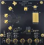
5.3
Board Layouts
6492635
TLK1221 EVM
REV.
GND
5
6
7
7
8
9
8
9
LOO PEN
E NABLE
RBCMODE
P RBSEN
S YNCEN
N
VDD
RBC0
4
5
6
TX
VDD
VDDA
GND
4
G ND
TD
V DD
2
3
TD
1
2
3
TXP
VDDPLL
TD
VDD
SYNC
G ND
0
1
GND
0
RD
PIN 1
RD
TD
XN
R
RXP
RBC1
GND
REFCLK
GND
+
VDD_LED
VDDA_LED
VDDPLL_LED
+
GND
└
+
PULL -UPS
VDDA
VDDPLL
GND
GND
VDD
Figure 9. TLK1221 Board Layout: Top (Layer 1)
SLLU100 – September 2007
Submit Documentation Feedback
TLK1221 Ethernet Transceiver Evaluation Module (EVM)
11
�www.ti.com
Schematic, Bill of Materials, and Board Layouts
Figure 10. TLK1221 Board Layout: GND (Layer 2)
12
TLK1221 Ethernet Transceiver Evaluation Module (EVM)
SLLU100 – September 2007
Submit Documentation Feedback
�www.ti.com
Schematic, Bill of Materials, and Board Layouts
Figure 11. TLK1221 EVM Board Layout: Internal Signal (Layer 3)
SLLU100 – September 2007
Submit Documentation Feedback
TLK1221 Ethernet Transceiver Evaluation Module (EVM)
13
�www.ti.com
Schematic, Bill of Materials, and Board Layouts
Figure 12. TLK1221 Board Layout: GND (Layers 4,6,8,9)
14
TLK1221 Ethernet Transceiver Evaluation Module (EVM)
SLLU100 – September 2007
Submit Documentation Feedback
�www.ti.com
Schematic, Bill of Materials, and Board Layouts
Figure 13. TLK1221 Board Layout: Internal Signal and VDDPLL (Layer 5)
SLLU100 – September 2007
Submit Documentation Feedback
TLK1221 Ethernet Transceiver Evaluation Module (EVM)
15
�www.ti.com
Schematic, Bill of Materials, and Board Layouts
Figure 14. TLK1221 Board Layout: VDDA and VDD (Layer 7)
16
TLK1221 Ethernet Transceiver Evaluation Module (EVM)
SLLU100 – September 2007
Submit Documentation Feedback
�www.ti.com
Schematic, Bill of Materials, and Board Layouts
Figure 15. TLK1221 Board Layout: Bottom (Layer 10)
SLLU100 – September 2007
Submit Documentation Feedback
TLK1221 Ethernet Transceiver Evaluation Module (EVM)
17
�www.ti.com
Schematic, Bill of Materials, and Board Layouts
Table 4. TLK1221 EVM PCB Layer Construction
Subclass Name
TOP
L2_GND
L3_SIG
L4_GND
L5_SIG/VDDPLL
L6_GND
L7_VDD/VDDA
L8_GND
L9_GND
BOTTOM
Type
Thickness
(MIL)
Conductivity
(mho/cm)
Dielectric
Constant
Loss
Tangent
SURFACE
AIR
CONDUCTOR
COPPER
2.4
595900
1
0
DIELECTRIC
FR-4
4.5
0
4.1
0.035
PLANE
COPPER
1.2
595900
1
0
DIELECTRIC
FR-4
7.5
0
4.1
0.035
CONDUCTOR
COPPER
1.2
595900
1
0
DIELECTRIC
FR-4
7.5
0
4.1
0.035
PLANE
COPPER
1.2
595900
1
0
DIELECTRIC
FR-4
7.5
0
4.1
0.035
CONDUCTOR
COPPER
1.2
595900
1
0
DIELECTRIC
FR-4
7.5
0
4.1
0.035
PLANE
COPPER
1.2
595900
1
0
DIELECTRIC
FR-4
7.5
0
4.1
0.035
PLANE
COPPER
1.2
595900
1
0
DIELECTRIC
FR-4
7.5
0
4.1
0.035
PLANE
COPPER
1.2
595900
1
0
DIELECTRIC
FR-4
7.5
0
4.1
0.035
PLANE
COPPER
1.2
595900
1
0
DIELECTRIC
FR-4
4.5
0
4.1
0.035
CONDUCTOR
COPPER
2.4
595900
1
0
SURFACE
AIR
Note:
18
Material
Artwork
POSITIVE
Width
(MIL)
Impedance
(Ω)
8
49.307
6.5
50.349
6.5
50.349
8
49.307
NEGATIVE
POSITIVE
NEGATIVE
POSITIVE
NEGATIVE
NEGATIVE
NEGATIVE
NEGATIVE
POSITIVE
Always consult with your board manufacturer for their process/design requirements to ensure
the desired impedance is achieved.
TLK1221 Ethernet Transceiver Evaluation Module (EVM)
SLLU100 – September 2007
Submit Documentation Feedback
�EVALUATION BOARD/KIT IMPORTANT NOTICE
Texas Instruments (TI) provides the enclosed product(s) under the following conditions:
This evaluation board/kit is intended for use for ENGINEERING DEVELOPMENT, DEMONSTRATION, OR EVALUATION PURPOSES
ONLY and is not considered by TI to be a finished end-product fit for general consumer use. Persons handling the product(s) must have
electronics training and observe good engineering practice standards. As such, the goods being provided are not intended to be complete
in terms of required design-, marketing-, and/or manufacturing-related protective considerations, including product safety and environmental
measures typically found in end products that incorporate such semiconductor components or circuit boards. This evaluation board/kit does
not fall within the scope of the European Union directives regarding electromagnetic compatibility, restricted substances (RoHS), recycling
(WEEE), FCC, CE or UL, and therefore may not meet the technical requirements of these directives or other related directives.
Should this evaluation board/kit not meet the specifications indicated in the User’s Guide, the board/kit may be returned within 30 days from
the date of delivery for a full refund. THE FOREGOING WARRANTY IS THE EXCLUSIVE WARRANTY MADE BY SELLER TO BUYER
AND IS IN LIEU OF ALL OTHER WARRANTIES, EXPRESSED, IMPLIED, OR STATUTORY, INCLUDING ANY WARRANTY OF
MERCHANTABILITY OR FITNESS FOR ANY PARTICULAR PURPOSE.
The user assumes all responsibility and liability for proper and safe handling of the goods. Further, the user indemnifies TI from all claims
arising from the handling or use of the goods. Due to the open construction of the product, it is the user’s responsibility to take any and all
appropriate precautions with regard to electrostatic discharge.
EXCEPT TO THE EXTENT OF THE INDEMNITY SET FORTH ABOVE, NEITHER PARTY SHALL BE LIABLE TO THE OTHER FOR ANY
INDIRECT, SPECIAL, INCIDENTAL, OR CONSEQUENTIAL DAMAGES.
TI currently deals with a variety of customers for products, and therefore our arrangement with the user is not exclusive.
TI assumes no liability for applications assistance, customer product design, software performance, or infringement of patents or
services described herein.
Please read the User’s Guide and, specifically, the Warnings and Restrictions notice in the User’s Guide prior to handling the product. This
notice contains important safety information about temperatures and voltages. For additional information on TI’s environmental and/or
safety programs, please contact the TI application engineer or visit www.ti.com/esh.
No license is granted under any patent right or other intellectual property right of TI covering or relating to any machine, process, or
combination in which such TI products or services might be or are used.
FCC Warning
This evaluation board/kit is intended for use for ENGINEERING DEVELOPMENT, DEMONSTRATION, OR EVALUATION PURPOSES
ONLY and is not considered by TI to be a finished end-product fit for general consumer use. It generates, uses, and can radiate radio
frequency energy and has not been tested for compliance with the limits of computing devices pursuant to part 15 of FCC rules, which are
designed to provide reasonable protection against radio frequency interference. Operation of this equipment in other environments may
cause interference with radio communications, in which case the user at his own expense will be required to take whatever measures may
be required to correct this interference.
Mailing Address: Texas Instruments, Post Office Box 655303, Dallas, Texas 75265
Copyright © 2007, Texas Instruments Incorporated
EVM WARNINGS AND RESTRICTIONS
It is important to operate this EVM within the input voltage range of 0 V to 3.6 V and the output voltage range of 0 V to 2.9 V or Vdd V.
Exceeding the specified input range may cause unexpected operation and/or irreversible damage to the EVM. If there are questions
concerning the input range, please contact a TI field representative prior to connecting the input power.
Applying loads outside of the specified output range may result in unintended operation and/or possible permanent damage to the EVM.
Please consult the EVM User's Guide prior to connecting any load to the EVM output. If there is uncertainty as to the load specification,
please contact a TI field representative.
During normal operation, some circuit components may have case temperatures greater than 50°C. The EVM is designed to operate
properly with certain components above 40°C as long as the input and output ranges are maintained. These components include but are
not limited to linear regulators, switching transistors, pass transistors, and current sense resistors. These types of devices can be identified
using the EVM schematic located in the EVM User's Guide. When placing measurement probes near these devices during operation,
please be aware that these devices may be very warm to the touch.
Mailing Address: Texas Instruments, Post Office Box 655303, Dallas, Texas 75265
Copyright © 2007, Texas Instruments Incorporated
�IMPORTANT NOTICE
Texas Instruments Incorporated and its subsidiaries (TI) reserve the right to make corrections, modifications, enhancements,
improvements, and other changes to its products and services at any time and to discontinue any product or service without notice.
Customers should obtain the latest relevant information before placing orders and should verify that such information is current and
complete. All products are sold subject to TI’s terms and conditions of sale supplied at the time of order acknowledgment.
TI warrants performance of its hardware products to the specifications applicable at the time of sale in accordance with TI’s
standard warranty. Testing and other quality control techniques are used to the extent TI deems necessary to support this
warranty. Except where mandated by government requirements, testing of all parameters of each product is not necessarily
performed.
TI assumes no liability for applications assistance or customer product design. Customers are responsible for their products and
applications using TI components. To minimize the risks associated with customer products and applications, customers should
provide adequate design and operating safeguards.
TI does not warrant or represent that any license, either express or implied, is granted under any TI patent right, copyright, mask
work right, or other TI intellectual property right relating to any combination, machine, or process in which TI products or services
are used. Information published by TI regarding third-party products or services does not constitute a license from TI to use such
products or services or a warranty or endorsement thereof. Use of such information may require a license from a third party under
the patents or other intellectual property of the third party, or a license from TI under the patents or other intellectual property of TI.
Reproduction of TI information in TI data books or data sheets is permissible only if reproduction is without alteration and is
accompanied by all associated warranties, conditions, limitations, and notices. Reproduction of this information with alteration is an
unfair and deceptive business practice. TI is not responsible or liable for such altered documentation. Information of third parties
may be subject to additional restrictions.
Resale of TI products or services with statements different from or beyond the parameters stated by TI for that product or service
voids all express and any implied warranties for the associated TI product or service and is an unfair and deceptive business
practice. TI is not responsible or liable for any such statements.
TI products are not authorized for use in safety-critical applications (such as life support) where a failure of the TI product would
reasonably be expected to cause severe personal injury or death, unless officers of the parties have executed an agreement
specifically governing such use. Buyers represent that they have all necessary expertise in the safety and regulatory ramifications
of their applications, and acknowledge and agree that they are solely responsible for all legal, regulatory and safety-related
requirements concerning their products and any use of TI products in such safety-critical applications, notwithstanding any
applications-related information or support that may be provided by TI. Further, Buyers must fully indemnify TI and its
representatives against any damages arising out of the use of TI products in such safety-critical applications.
TI products are neither designed nor intended for use in military/aerospace applications or environments unless the TI products are
specifically designated by TI as military-grade or "enhanced plastic." Only products designated by TI as military-grade meet military
specifications. Buyers acknowledge and agree that any such use of TI products which TI has not designated as military-grade is
solely at the Buyer's risk, and that they are solely responsible for compliance with all legal and regulatory requirements in
connection with such use.
TI products are neither designed nor intended for use in automotive applications or environments unless the specific TI products
are designated by TI as compliant with ISO/TS 16949 requirements. Buyers acknowledge and agree that, if they use any
non-designated products in automotive applications, TI will not be responsible for any failure to meet such requirements.
Following are URLs where you can obtain information on other Texas Instruments products and application solutions:
Products
Applications
Amplifiers
amplifier.ti.com
Audio
www.ti.com/audio
Data Converters
dataconverter.ti.com
Automotive
www.ti.com/automotive
DSP
dsp.ti.com
Broadband
www.ti.com/broadband
Interface
interface.ti.com
Digital Control
www.ti.com/digitalcontrol
Logic
logic.ti.com
Military
www.ti.com/military
Power Mgmt
power.ti.com
Optical Networking
www.ti.com/opticalnetwork
Microcontrollers
microcontroller.ti.com
Security
www.ti.com/security
RFID
www.ti-rfid.com
Telephony
www.ti.com/telephony
Low Power
Wireless
www.ti.com/lpw
Video & Imaging
www.ti.com/video
Wireless
www.ti.com/wireless
Mailing Address: Texas Instruments, Post Office Box 655303, Dallas, Texas 75265
Copyright © 2007, Texas Instruments Incorporated
�