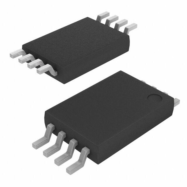
TLV9301, TLV9302, TLV9304
SBOS941D – FEBRUARY 2019 – REVISED AUGUST 2021
TLV930x 40-V, 1-MHz, RRO Operational Amplifiers for Cost-Sensitive Systems
1 Features
3 Description
•
•
•
•
•
•
•
•
•
•
•
•
The TLV930x family (TLV9301, TLV9302, and
TLV9304) is a family of 40-V, cost-optimized
operational amplifiers. These devices offer strong
general-purpose DC and AC specifications, including
rail-to-rail output, low offset (±0.5 mV, typ), low offset
drift (±2 µV/°C, typ), and 1-MHz bandwidth.
•
Low offset voltage: ±0.5 mV
Low offset voltage drift: ±2 µV/°C
Low noise: 33 nV/√Hz at 1 kHz
High common-mode rejection: 110 dB
Low bias current: ±10 pA
Rail-to-rail output
Wide bandwidth: 1-MHz GBW
High slew rate: 3 V/µs
Low quiescent current: 150 µA per amplifier
Wide supply: ±2.25 V to ±20 V, 4.5 V to 40 V
Robust EMI performance: 72 dB at 1 GHz
MUX-friendly/comparator inputs:
– Differential and common-mode input voltage
range to supply rail
Industry-standard packages:
– Single in SOT-23-5 and SC70
– Dual in SOIC-8, TSSOP-8, and VSSOP-8
– Quad in SOIC-14 and TSSOP-14
Convenient features such as wide differential inputvoltage range, high output current (±60 mA), and
high slew rate (3 V/µs) make the TLV930x a robust
operational amplifier for high-voltage, cost-sensitive
applications.
The TLV930x family of op amps is available in
standard packages and is specified from –40°C to
125°C.
Device Information
PART NUMBER(1)
TLV9301
2 Applications
•
•
•
•
•
Merchant network and server PSU
Industrial AC-DC
Merchant DC/DC
Motor drives: AC and servo drive power supplies
Building automation
TLV9302
TLV9304
(1)
RG
PACKAGE
BODY SIZE (NOM)
SOT-23 (5)
2.90 mm × 1.60 mm
SC70 (5)
2.00 mm × 1.25 mm
SOIC (8)
4.90 mm × 3.91 mm
SOT-23-8
2.90 mm × 1.60 mm
TSSOP (8)
4.40 mm × 3.00 mm
VSSOP (8)
2.30 mm × 2.00 mm
SOIC (14)
8.65 mm × 3.91 mm
TSSOP (14)
5.00 mm × 4.40 mm
For all available packages, see the orderable addendum at
the end of the data sheet.
RF
R1
VOUT
VIN
C1
f-3 dB =
(
RF
VOUT
= 1+
RG
VIN
((
1
1 + sR1C1
1
2pR1C1
(
TLV930x in a Single-Pole, Low-Pass Filter
An IMPORTANT NOTICE at the end of this data sheet addresses availability, warranty, changes, use in safety-critical applications,
intellectual property matters and other important disclaimers. PRODUCTION DATA.
�TLV9301, TLV9302, TLV9304
www.ti.com
SBOS941D – FEBRUARY 2019 – REVISED AUGUST 2021
Table of Contents
1 Features............................................................................1
2 Applications..................................................................... 1
3 Description.......................................................................1
4 Revision History.............................................................. 2
5 Pin Configuration and Functions...................................3
6 Specifications.................................................................. 5
6.1 Absolute Maximum Ratings ....................................... 5
6.2 ESD Ratings .............................................................. 5
6.3 Recommended Operating Conditions ........................5
6.4 Thermal Information for Single Channel .................... 5
6.5 Thermal Information for Dual Channel .......................6
6.6 Thermal Information for Quad Channel ..................... 6
6.7 Electrical Characteristics ............................................7
6.8 Typical Characteristics................................................ 9
7 Detailed Description......................................................16
7.1 Overview................................................................... 16
7.2 Functional Block Diagram......................................... 16
7.3 Feature Description...................................................17
7.4 Device Functional Modes..........................................24
8 Application and Implementation.................................. 25
8.1 Application Information............................................. 25
8.2 Typical Applications.................................................. 25
9 Power Supply Recommendations................................27
10 Layout...........................................................................27
10.1 Layout Guidelines................................................... 27
10.2 Layout Example...................................................... 27
11 Device and Documentation Support..........................30
11.1 Device Support........................................................30
11.2 Documentation Support.......................................... 30
11.3 Receiving Notification of Documentation Updates.. 30
11.4 Support Resources................................................. 30
11.5 Trademarks............................................................. 30
11.6 Electrostatic Discharge Caution.............................. 31
11.7 Glossary.................................................................. 31
12 Mechanical, Packaging, and Orderable
Information.................................................................... 32
4 Revision History
NOTE: Page numbers for previous revisions may differ from page numbers in the current version.
Changes from Revision C (February 2021) to Revision D (August 2021)
Page
• Removed preview note and added thermal data for VSSOP-8 (DGK) package in Thermal Information for Dual
Channel.............................................................................................................................................................. 6
Changes from Revision B (March 2020) to Revision C (February 2021)
Page
• Updated the numbering format for tables, figures, and cross-references throughout the document..................1
• Removed preview notation from TLV9302 SOT-23 (8) package from Device Information table........................ 1
• Removed preview notation from TLV9302 VSSOP (8) package from Device Information table........................ 1
• Removed Table of Graphs table from the Specifications section....................................................................... 9
• Removed Related Links section from the Device and Documentation Support section...................................30
Changes from Revision A (April 2019) to Revision B (March 2020)
Page
• Changed the TLV9301 and TLV9304 device statuses from Advance Information to Production Data ..............1
• Removed preview notation from TLV9301 SOT-23 (5) package from Device Information table........................ 1
• Removed preview notation from TLV9301 SC70 (5) package from Device Information table............................1
• Removed preview notation from TLV9304 SOIC (14) package from Device Information table.......................... 1
• Removed preview notation from TLV9304 TSSOP (14) package from Device Information table...................... 1
• Removed preview notation from TLV9301 DBV package (SOT-23) in the Pin Configuration and Functions
section................................................................................................................................................................ 3
• Removed preview notation from TLV9301 DCK package (SC70) in the Pin Configuration and Functions
section................................................................................................................................................................ 3
• Removed preview notation from TLV9304 D (SOIC) and TSSOP (PW) packages in the Pin Configuration and
Functions section................................................................................................................................................3
Changes from Revision * (February 2019) to Revision A (April 2019)
Page
• Changed the TLV9302 device status from Advance Information to Production Data ........................................1
2
Submit Document Feedback
Copyright © 2021 Texas Instruments Incorporated
Product Folder Links: TLV9301 TLV9302 TLV9304
�TLV9301, TLV9302, TLV9304
www.ti.com
SBOS941D – FEBRUARY 2019 – REVISED AUGUST 2021
5 Pin Configuration and Functions
OUT
1
V±
2
IN+
3
5
V+
4
IN±
IN+
1
V±
2
IN±
3
Not to scale
5
V+
4
OUT
Not to scale
Figure 5-1. TLV9301 DBV Package
5-Pin SOT-23
Top View
Figure 5-2. TLV9301 DCK Package
5-Pin SC70
Top View
Table 5-1. Pin Functions: TLV9301
PIN
NAME
DBV
DCK
+IN
3
1
–IN
4
OUT
1
V+
V–
I/O
DESCRIPTION
I
Noninverting input
3
I
Inverting input
4
O
Output
5
5
—
Positive (highest) power supply
2
2
—
Negative (lowest) power supply
OUT1
1
8
V+
IN1±
2
7
OUT2
IN1+
3
6
IN2±
V±
4
5
IN2+
Not to scale
Figure 5-3. TLV9302 D, DDF, DGK, and PW Package
8-Pin SOIC, TSOT, TSSOP, and VSSOP
Top View
Table 5-2. Pin Functions: TLV9302
PIN
NAME
NO.
I/O
DESCRIPTION
+IN A
3
I
Noninverting input, channel A
+IN B
5
I
Noninverting input, channel B
–IN A
2
I
Inverting input, channel A
–IN B
6
I
Inverting input, channel B
OUT A
1
O
Output, channel A
OUT B
7
O
Output, channel B
V+
8
—
Positive (highest) power supply
V–
4
—
Negative (lowest) power supply
Submit Document Feedback
Copyright © 2021 Texas Instruments Incorporated
Product Folder Links: TLV9301 TLV9302 TLV9304
3
�TLV9301, TLV9302, TLV9304
www.ti.com
SBOS941D – FEBRUARY 2019 – REVISED AUGUST 2021
OUT1
1
14
OUT4
IN1±
2
13
IN4±
IN1+
3
12
IN4+
V+
4
11
V±
IN2+
5
10
IN3+
IN2±
6
9
IN3±
OUT2
7
8
OUT3
Not to scale
Figure 5-4. TLV9304 D and PW Package
14-Pin SOIC and TSSOP
Top View
Table 5-3. Pin Functions: TLV9304
PIN
NAME
4
NO.
I/O
DESCRIPTION
+IN A
3
I
Noninverting input, channel A
+IN B
5
I
Noninverting input, channel B
+IN C
10
I
Noninverting input, channel C
+IN D
12
I
Noninverting input, channel D
–IN A
2
I
Inverting input, channel A
–IN B
6
I
Inverting input, channel B
–IN C
9
I
Inverting input, channel C
–IN D
13
I
Inverting input, channel D
OUT A
1
O
Output, channel A
OUT B
7
O
Output, channel B
OUT C
8
O
Output, channel C
OUT D
14
O
Output, channel D
V+
4
—
Positive (highest) power supply
V–
11
—
Negative (lowest) power supply
Submit Document Feedback
Copyright © 2021 Texas Instruments Incorporated
Product Folder Links: TLV9301 TLV9302 TLV9304
�TLV9301, TLV9302, TLV9304
www.ti.com
SBOS941D – FEBRUARY 2019 – REVISED AUGUST 2021
6 Specifications
6.1 Absolute Maximum Ratings
over operating ambient temperature range (unless otherwise noted)(1)
MIN
MAX
0
42
V
(V–) – 0.5
(V+) + 0.5
V
Supply voltage, VS = (V+) – (V–)
Common-mode
voltage(3)
Differential voltage(3) (4)
Signal input pins
VS + 0.2
Current(3)
–10
Output short-circuit(2)
–55
Junction temperature, TJ
Storage temperature, Tstg
(2)
(3)
(4)
V
10
mA
150
°C
150
°C
150
°C
Continuous
Operating ambient temperature, TA
(1)
UNIT
–65
Stresses beyond those listed under Absolute Maximum Ratings may cause permanent damage to the device. These are stress
ratings only, which do not imply functional operation of the device at these or any other conditions beyond those indicated under
Recommended Operating Conditions. Exposure to absolute-maximum-rated conditions for extended periods may affect device
reliability.
Short-circuit to ground, one amplifier per package.
Input pins are diode-clamped to the power-supply rails. Input signals that may swing more than 0.5 V beyond the supply rails must be
current limited to 10 mA or less.
Large differential voltages applied between IN+ and IN– for extended periods of time may cause a long-term shift to the input offset
voltage. This effect increases as temperature rises above 25°C.
6.2 ESD Ratings
VALUE
V(ESD)
(1)
(2)
Electrostatic discharge
Human-body model (HBM), per ANSI/ESDA/JEDEC
JS-001(1)
UNIT
±2000
Charged-device model (CDM), per JEDEC specification JESD22-C101(2)
V
±1000
JEDEC document JEP155 states that 500-V HBM allows safe manufacturing with a standard ESD control process.
JEDEC document JEP157 states that 250-V CDM allows safe manufacturing with a standard ESD control process.
6.3 Recommended Operating Conditions
over operating ambient temperature range (unless otherwise noted)
VS
Supply voltage, (V+) – (V–)
VI
Input voltage range
TA
Specified temperature
MIN
MAX
4.5
40
UNIT
(V–) – 0.1
(V+) – 2
V
–40
125
°C
V
6.4 Thermal Information for Single Channel
TLV9301
THERMAL
METRIC(1)
DBV (SOT-23)
DCK (SC70)
5 PINS
5 PINS
UNIT
RθJA
Junction-to-ambient thermal resistance
192.5
203.9
°C/W
RθJC(top)
Junction-to-case (top) thermal resistance
113.3
116.2
°C/W
RθJB
Junction-to-board thermal resistance
60.2
51.7
°C/W
ψJT
Junction-to-top characterization parameter
37.6
24.6
°C/W
ψJB
Junction-to-board characterization parameter
60.1
51.9
°C/W
RθJC(bot)
Junction-to-case (bottom) thermal resistance
N/A
N/A
°C/W
(1)
For more information about traditional and new thermal metrics, see the Semiconductor and IC Package Thermal Metrics application
report, SPRA953.
Submit Document Feedback
Copyright © 2021 Texas Instruments Incorporated
Product Folder Links: TLV9301 TLV9302 TLV9304
5
�TLV9301, TLV9302, TLV9304
www.ti.com
SBOS941D – FEBRUARY 2019 – REVISED AUGUST 2021
6.5 Thermal Information for Dual Channel
TLV9302
THERMAL METRIC(1)
D (SOIC)
DDF (SOT-23-8)
DGK (VSSOP)
PW (TSSOP)
8 PINS
8 PINS
8 PINS
8 PINS
UNIT
RθJA
Junction-to-ambient thermal
resistance
138.7
150.4
189.3
188.4
°C/W
RθJC(top)
Junction-to-case (top) thermal
resistance
78.7
85.6
75.8
77.1
°C/W
RθJB
Junction-to-board thermal resistance
82.2
70.0
111.0
119.1
°C/W
ψJT
Junction-to-top characterization
parameter
27.8
8.1
15.4
14.2
°C/W
ψJB
Junction-to-board characterization
parameter
81.4
69.6
109.3
117.4
°C/W
RθJC(bot)
Junction-to-case (bottom) thermal
resistance
N/A
N/A
N/A
N/A
°C/W
(1)
For more information about traditional and new thermal metrics, see the Semiconductor and IC Package Thermal Metrics application
report, SPRA953.
6.6 Thermal Information for Quad Channel
TLV9304
THERMAL
D (SOIC)
PW (TSSOP)
14 PINS
14 PINS
UNIT
RθJA
Junction-to-ambient thermal resistance
105.5
134.5
°C/W
RθJC(top)
Junction-to-case (top) thermal resistance
61.4
55.4
°C/W
RθJB
Junction-to-board thermal resistance
61.0
79.2
°C/W
ψJT
Junction-to-top characterization parameter
21.6
9.3
°C/W
ψJB
Junction-to-board characterization parameter
60.3
78.4
°C/W
RθJC(bot)
Junction-to-case (bottom) thermal resistance
N/A
N/A
°C/W
(1)
6
METRIC(1)
For more information about traditional and new thermal metrics, see the Semiconductor and IC Package Thermal Metrics application
report, SPRA953.
Submit Document Feedback
Copyright © 2021 Texas Instruments Incorporated
Product Folder Links: TLV9301 TLV9302 TLV9304
�TLV9301, TLV9302, TLV9304
www.ti.com
SBOS941D – FEBRUARY 2019 – REVISED AUGUST 2021
6.7 Electrical Characteristics
For VS = (V+) – (V–) = 4.5 V to 40 V (±2.25 V to ±20 V) at TA = 25°C, RL = 10 kΩ connected to VS / 2, VCM = VS / 2, and
VOUT = VS / 2, unless otherwise noted.
PARAMETER
TEST CONDITIONS
MIN
TYP
MAX
UNIT
OFFSET VOLTAGE
Input offset voltage
dVOS/dT
Input offset voltage drift
TA = –40°C to 125°C
±2
PSRR
Input offset voltage versus
VCM = V–
power supply
TA = –40°C to 125°C
±2
Channel separation
VCM = V–
±0.5
VOS
TA = –40°C to 125°C
±2.5
mV
±2.75
f = 0 Hz
µV/℃
±5
µV/V
5
µV/V
INPUT BIAS CURRENT
IB
Input bias current
±10
pA
IOS
Input offset current
±10
pA
NOISE
EN
Input voltage noise
eN
Input voltage noise density
iN
Input current noise
f = 0.1 Hz to 10 Hz
6
µVPP
1
µVRMS
f = 1 kHz
33
f = 10 kHz
30
f = 1 kHz
5
nV/√Hz
fA/√Hz
INPUT VOLTAGE RANGE
VCM
Common-mode voltage
range
(V–) – 0.2
VS = 40 V, (V–) – 0.1 V < VCM
< (V+) – 2 V
CMRR
Common-mode rejection
ratio
VS = 4.5 V, (V–) – 0.1 V <
VCM < (V+) – 2 V
95
(V+) – 2
V
110
dB
90
TA = –40°C to 125°C
(V+) – 2 V < VCM < (V+) + 0.1
V
See Common-Mode Voltage Range
INPUT CAPACITANCE
ZID
Differential
110 || 4
MΩ || pF
ZICM
Common-mode
6 || 1.5
TΩ || pF
OPEN-LOOP GAIN
AOL
Open-loop voltage gain
VS = 40 V, VCM = V–
(V–) + 0.1 V < VO < (V+) –
0.1 V
TA = –40°C to 125°C
120
130
116
127
dB
FREQUENCY RESPONSE
GBW
Gain-bandwidth product
SR
Slew rate
tS
THD+N
Settling time
1
MHz
VS = 40 V, G = +1, CL = 20 pF
3
V/µs
To 0.1%, VS = 40 V, VSTEP = 10 V , G = +1, CL = 20 pF
5
To 0.1%, VS = 40 V, VSTEP = 2 V , G = +1, CL = 20 pF
To 0.01%, VS = 40 V, VSTEP = 10 V , G = +1, CL = 20 pF
2.5
6
µs
To 0.01%, VS = 40 V, VSTEP = 2 V , G = +1, CL = 20 pF
3.5
Phase margin
G = +1, RL = 10 kΩ, CL = 20 pF
60
°
Overload recovery time
VIN × gain > VS
1
µs
Total harmonic distortion +
VS = 40 V, VO = 1 VRMS, G = -1, f = 1 kHz
noise
0.003%
Submit Document Feedback
Copyright © 2021 Texas Instruments Incorporated
Product Folder Links: TLV9301 TLV9302 TLV9304
7
�TLV9301, TLV9302, TLV9304
www.ti.com
SBOS941D – FEBRUARY 2019 – REVISED AUGUST 2021
6.7 Electrical Characteristics (continued)
For VS = (V+) – (V–) = 4.5 V to 40 V (±2.25 V to ±20 V) at TA = 25°C, RL = 10 kΩ connected to VS / 2, VCM = VS / 2, and
VOUT = VS / 2, unless otherwise noted.
PARAMETER
TEST CONDITIONS
MIN
TYP
MAX
UNIT
OUTPUT
VS = 40 V, RL = no load
Voltage output swing from
rail
Positive and negative rail
headroom
50
75
VS = 40 V, RL = 2 kΩ
250
350
VS = 4.5 V, RL = no load
VS = 4.5 V, RL = 10 kΩ
VS = 4.5 V, RL = 2 kΩ
ISC
Short-circuit current
CLOAD
Capacitive load drive
ZO
Open-loop output
impedance
3
VS = 40 V, RL = 10 kΩ
1
20
30
40
75
±60
mV
mA
See Typical Characteristics
f = 1 MHz, IO = 0 A
600
Ω
POWER SUPPLY
IQ
8
Quiescent current per
amplifier
IO = 0 A
150
TA = –40°C to 125°C
Submit Document Feedback
175
175
µA
Copyright © 2021 Texas Instruments Incorporated
Product Folder Links: TLV9301 TLV9302 TLV9304
�TLV9301, TLV9302, TLV9304
www.ti.com
SBOS941D – FEBRUARY 2019 – REVISED AUGUST 2021
6.8 Typical Characteristics
25%
25%
20%
20%
Population (%)
15%
10%
15%
10%
5%
Offset Voltage (PV)
6
5.5
5
4.5
4
3.5
3
2.5
2
1.5
D001
1
0
0.5
2000
1750
1500
1250
750
1000
500
0
250
-250
-500
-750
-1000
-1250
-1500
-1750
-2000
0
5%
0
Population (%)
at TA = 25°C, VS = ±20 V, VCM = VS / 2, RLOAD = 10 kΩ connected to VS / 2, and CL = 100 pF (unless otherwise noted)
Offset Voltage Drift (PV/qC)
D002
TA = 25°C
Figure 6-1. Offset Voltage Production Distribution
Figure 6-2. Offset Voltage Drift Distribution
1000
1200
800
900
Offset Voltage (µV)
Offset Voltage (µV)
600
400
200
0
-200
-400
600
300
0
-300
-600
-600
-900
-800
-1000
-40
-20
0
20
40
60
80
Temperature (°C)
100
120
-1200
-40
140
-20
0
20
D003
100
120
140
D004
VCM = V–
VCM = V+
Figure 6-4. Offset Voltage vs Temperature
Figure 6-3. Offset Voltage vs Temperature
800
750
600
600
450
400
Offset Voltage (µV)
Offset Voltage (µV)
40
60
80
Temperature (°C)
200
0
-200
-400
300
150
0
-150
-300
-450
-600
-800
-20
-600
-750
-16
-12
-8
-4
0
4
8
Common Mode Voltage (V)
12
16
20
0
4
8
12
D005
16 20 24 28
Supply Voltage (V)
32
36
40
44
D008
TA = 25°C
Figure 6-5. Offset Voltage vs Common-Mode Voltage
Figure 6-6. Offset Voltage vs Power Supply
Submit Document Feedback
Copyright © 2021 Texas Instruments Incorporated
Product Folder Links: TLV9301 TLV9302 TLV9304
9
�TLV9301, TLV9302, TLV9304
www.ti.com
SBOS941D – FEBRUARY 2019 – REVISED AUGUST 2021
6.8 Typical Characteristics (continued)
at TA = 25°C, VS = ±20 V, VCM = VS / 2, RLOAD = 10 kΩ connected to VS / 2, and CL = 100 pF (unless otherwise noted)
150
Gain
Phase
80
G=1
G = -1
G = 10
G = 100
G = 1000
60
125
50
100
40
75
20
50
0
25
-20
100
0
Phase (q)
Gain (dB)
60
70
Closed-Loop Gain (dB)
100
40
30
20
10
0
-10
-20
1k
10k
100k
Frequency (Hz)
-30
100
1M
1k
10k
100k
Frequency (Hz)
C002
1M
C001
CLOAD = 15 pF
Figure 6-8. Closed-Loop Gain and Phase vs Frequency
Figure 6-7. Open-Loop Gain and Phase vs Frequency
320
IB
IB+
IOS
2.5
2
Input Bias and Offset Current (pA)
Input Bias and Offset Current (pA)
3
1.5
1
0.5
0
-0.5
-1
-1.5
-2
-2.5
-20
-16
-12
-8
-4
0
4
8
Common Mode Voltage (V)
12
16
200
160
120
80
40
0
V+
V + 10 V
1V
V +9V
V+
2V
V +8V
V+
3V
4V
V+
5V
V+
6V
V+
7V
V+
8V
V+
V+
-40°C
25°C
85°C
125°C
9V
0
20
40
60
80
Temperature (°C)
100
120
140
D011
Figure 6-10. Input Bias Current vs Temperature
V+
V+
-20
D010
Output Voltage (V)
Output Voltage (V)
240
-40
-40
20
Figure 6-9. Input Bias Current vs Common-Mode Voltage
-40°C
25°C
85°C
125°C
V +7V
V +6V
V +5V
V +4V
V +3V
V +2V
V +1V
10 V
V
0
10
20
30
40
50
60
70
Output Current (mA)
80
90
100
0
10
20
D012
Figure 6-11. Output Voltage Swing vs Output Current (Sourcing)
10
IB
IB+
IOS
280
30
40
50
60
70
Output Current (mA)
80
90
100
D012
Figure 6-12. Output Voltage Swing vs Output Current (Sinking)
Submit Document Feedback
Copyright © 2021 Texas Instruments Incorporated
Product Folder Links: TLV9301 TLV9302 TLV9304
�TLV9301, TLV9302, TLV9304
www.ti.com
SBOS941D – FEBRUARY 2019 – REVISED AUGUST 2021
6.8 Typical Characteristics (continued)
at TA = 25°C, VS = ±20 V, VCM = VS / 2, RLOAD = 10 kΩ connected to VS / 2, and CL = 100 pF (unless otherwise noted)
5
5
-40qC
4.5
4.5
4
3.5
Output Voltage (V)
Output Voltage (V)
4
25qC
125qC
3
2.5
85qC
2
1.5
3.5
3
125qC
2
1.5
1
1
0.5
0.5
0
85qC
2.5
25qC
0
0
10
20
30
40
50
60
70
Output Current (mA)
80
90
100
0
10
20
D013
30
40
50
60
70
Output Current (mA)
VS = 5 V
80
90
100
D013
VS = 5 V
Figure 6-13. Output Voltage Swing vs Output Current (Sourcing)
Figure 6-14. Output Voltage Swing vs Output Current (Sinking)
120
110
90
Common-Mode Rejection Ratio (dB)
PSRR+
PSRRCMRR
100
PSRR and CMRR (dB)
-40qC
80
70
60
50
40
30
20
10
0
100
1k
10k
100k
Frequency (Hz)
1M
115
110
105
100
95
90
-40
10M
-20
0
C003
20
40
60
80
Temperature (°C)
100
120
140
D015
f = 0 Hz
Figure 6-15. CMRR and PSRR vs Frequency
Figure 6-16. CMRR vs Temperature (dB)
1.8
1.6
1.4
Voltage (1uV/div)
Power Supply Rejection Ratio (µV/V)
2
1.2
1
0.8
0.6
0.4
0.2
0
-40
-20
0
20
40
60
80
Temperature (°C)
100
120
Time (1s/Div)
140
C015
D016
f = 0 Hz
Figure 6-17. PSRR vs Temperature (dB)
Figure 6-18. 0.1-Hz to 10-Hz Noise
Submit Document Feedback
Copyright © 2021 Texas Instruments Incorporated
Product Folder Links: TLV9301 TLV9302 TLV9304
11
�TLV9301, TLV9302, TLV9304
www.ti.com
SBOS941D – FEBRUARY 2019 – REVISED AUGUST 2021
6.8 Typical Characteristics (continued)
-40
120
RL = 10 k:
RL = 2 k:
RL = 600 :
RL = 128 :
110
-50
100
90
-60
80
THD+N (dB)
Input Voltage Noise Spectral Density (nV/rHz)
at TA = 25°C, VS = ±20 V, VCM = VS / 2, RLOAD = 10 kΩ connected to VS / 2, and CL = 100 pF (unless otherwise noted)
70
60
50
40
-70
-80
-90
30
20
-100
10
-110
0
10
100
1k
Frequency (Hz)
10k
100
100k
1k
Frequency (Hz)
C017
10k
C012
BW = 80 kHz, VOUT = 3.5 VRMS
Figure 6-20. THD+N Ratio vs Frequency
Figure 6-19. Input Voltage Noise Spectral Density vs Frequency
150
-40
145
Quiescent current (µA)
-30
THD+N (dB)
-50
-60
-70
-80
RL = 10 k:
RL = 2 k:
RL = 549 :
RL = 128 :
-90
-100
0.001
140
135
130
125
120
115
0.01
0.1
Amplitude (VRMS)
1
110
10 20
0
4
8
12
C023
16
20
24
28
Supply Voltage (V)
32
36
40
D021
BW = 80 kHz, f = 1 kHz
Figure 6-21. THD+N vs Output Amplitude
Figure 6-22. Quiescent Current vs Supply Voltage
152
150
Open Loop Voltage Gain (dB)
Quiescent current (µA)
148
145
140
135
144
140
136
132
128
124
130
-40
-20
0
20
40
60
80
Temperature (°C)
100
120
Figure 6-23. Quiescent Current vs Temperature
12
140
120
-40
-20
0
D022
20
40
60
80
Temperature (°C)
100
120
140
D023
Figure 6-24. Open-Loop Voltage Gain vs Temperature (dB)
Submit Document Feedback
Copyright © 2021 Texas Instruments Incorporated
Product Folder Links: TLV9301 TLV9302 TLV9304
�TLV9301, TLV9302, TLV9304
www.ti.com
SBOS941D – FEBRUARY 2019 – REVISED AUGUST 2021
6.8 Typical Characteristics (continued)
780
33
720
30
660
27
600
24
Overshoot (%)
Open Loop Output Impedance (:)
at TA = 25°C, VS = ±20 V, VCM = VS / 2, RLOAD = 10 kΩ connected to VS / 2, and CL = 100 pF (unless otherwise noted)
540
480
420
360
21
18
15
12
300
RISO = 0 :, Positive Overshoot
RISO = 0 :, Negative Overshoot
RISO = 50 :, Positive Overshoot
RISO = 50 :, Negative Overshoot
9
240
6
180
3
120
100
1k
10k
100k
Frequency (Hz)
1M
0
10M
40
80
120
C013
160 200 240
Cap Load (pF)
280
320
360
C007
G = –1, 100-mV output step
Figure 6-26. Small-Signal Overshoot vs Capacitive Load
55
64
50
60
45
56
40
52
Phase Margin (q)
Overshoot (%)
Figure 6-25. Open-Loop Output Impedance vs Frequency
35
30
25
20
10
40
80
120
160 200 240
Cap Load (pF)
280
320
40
36
28
24
5
0
44
32
RISO = 0 :, Positive Overshoot
RISO = 0 :, Negative Overshoot
RISO = 50 :, Positive Overshoot
RISO = 50 :, Negative Overshoot
15
48
20
360
0
100
200
300
C008
G = 1, 100-mV output step
400 500 600
Cap Load (pF)
700
800
900 1000
C009
G = –1, 100-mV output step
Figure 6-27. Small-Signal Overshoot vs Capacitive Load
Figure 6-28. Small-Signal Overshoot vs Capacitive Load
Voltage (5V/div)
Amplitude (2V/div)
Input
Output
Input
Output
Time (500ns/div)
Time (20µs/Div)
C018
C016
G = –10
Figure 6-29. No Phase Reversal
Figure 6-30. Positive Overload Recovery
Submit Document Feedback
Copyright © 2021 Texas Instruments Incorporated
Product Folder Links: TLV9301 TLV9302 TLV9304
13
�TLV9301, TLV9302, TLV9304
www.ti.com
SBOS941D – FEBRUARY 2019 – REVISED AUGUST 2021
6.8 Typical Characteristics (continued)
at TA = 25°C, VS = ±20 V, VCM = VS / 2, RLOAD = 10 kΩ connected to VS / 2, and CL = 100 pF (unless otherwise noted)
Voltage (5V/div)
Amplitude (5mV/div)
Input
Output
Input
Output
Time (500ns/div)
Time (2Ps/div)
C018
C010
G = –10
CL = 20 pF, G = 1, 20-mV step response
Figure 6-31. Negative Overload Recovery
Figure 6-32. Small-Signal Step Response
Amplitude (2V/div)
Amplitude (5mV/div)
Input
Output
Input
Output
Time (1µs/div)
Time (1µs/div)
C005
C011
CL = 20 pF, G = 1
RL = 1 kΩ, CL = 20 pF, G = –1, 10-mV step response
Figure 6-34. Large-Signal Step Response (Falling)
Amplitude (2V/div)
Large Signal Step Response (2V/div)
Figure 6-33. Small-Signal Step Response
Input
Output
Input
Output
Time (1µs/div)
Time (2µs/div)
C005
C021
CL = 20 pF, G = 1
Figure 6-35. Large-Signal Step Response (Rising)
14
CL = 10 pF, G = –1
Figure 6-36. Large-Signal Step Response
Submit Document Feedback
Copyright © 2021 Texas Instruments Incorporated
Product Folder Links: TLV9301 TLV9302 TLV9304
�TLV9301, TLV9302, TLV9304
www.ti.com
SBOS941D – FEBRUARY 2019 – REVISED AUGUST 2021
6.8 Typical Characteristics (continued)
100
45
80
40
60
Maximum Output Swing (V)
Short-Circuit Current (mA)
at TA = 25°C, VS = ±20 V, VCM = VS / 2, RLOAD = 10 kΩ connected to VS / 2, and CL = 100 pF (unless otherwise noted)
40
20
0
Sourcing
Sinking
-20
-40
-60
-80
-100
-40
-20
0
20
40
60
80
Temperature (°C)
100
120
30
25
20
15
10
0
1k
140
100
-70
90
-80
80
-90
-100
-120
40
Figure 6-39. Channel Separation vs Frequency
10M
C020
60
50
1M
1M
70
-110
10k
100k
Frequency (Hz)
100k
Frequency (Hz)
Figure 6-38. Maximum Output Voltage vs Frequency
-60
1k
10k
D038
EMIRR (dB)
Channel Seperation (dB)
35
5
Figure 6-37. Short-Circuit Current vs Temperature
-130
100
VS = 40 V
VS = 30 V
VS = 15 V
10M
30
1M
10M
C014
100M
Frequency (Hz)
1G
C004
Figure 6-40. EMIRR (Electromagnetic Interference Rejection
Ratio) vs Frequency
Submit Document Feedback
Copyright © 2021 Texas Instruments Incorporated
Product Folder Links: TLV9301 TLV9302 TLV9304
15
�TLV9301, TLV9302, TLV9304
SBOS941D – FEBRUARY 2019 – REVISED AUGUST 2021
www.ti.com
7 Detailed Description
7.1 Overview
The TLV930x family (TLV9301, TLV9302, and TLV9304) is a family of 40-V, cost-optimized operational
amplifiers. These devices offer strong general-purpose DC and AC specifications, including rail-to-rail output,
low offset (±0.5 mV, typ), low offset drift (±2 µV/°C, typ), and 1-MHz bandwidth.
Convenient features such as wide differential input-voltage range, high output current (±60 mA), and high slew
rate (3 V/µs) make the TLV930x a robust operational amplifier for high-voltage, cost-sensitive applications.
The TLV930x family of op amps is available in standard packages and is specified from –40°C to 125°C.
7.2 Functional Block Diagram
16
Submit Document Feedback
Copyright © 2021 Texas Instruments Incorporated
Product Folder Links: TLV9301 TLV9302 TLV9304
�TLV9301, TLV9302, TLV9304
www.ti.com
SBOS941D – FEBRUARY 2019 – REVISED AUGUST 2021
7.3 Feature Description
7.3.1 Input Protection Circuitry
The TLV930x uses a patented input architecture to eliminate the requirement for input protection diodes but still
provides robust input protection under transient conditions. Figure 7-1 shows conventional input diode protection
schemes that are activated by fast transient step responses and introduce signal distortion and settling time
delays because of alternate current paths, as shown in Figure 7-2. For low-gain circuits, these fast-ramping input
signals forward-bias back-to-back diodes, causing an increase in input current and resulting in extended settling
time.
V+
V+
VIN+
VIN+
VOUT
TLV930x
40 V
VOUT
~0.7 V
VIN
VIN
V
TLV930x Provides Full 40-V
Differential Input Range
V
Conventional Input Protection
Limits Differential Input Range
Figure 7-1. TLV930x Input Protection Does Not Limit Differential Input Capability
Vn = 10 V
RFILT
10 V
1
Ron_mux
Sn
1
D
10 V
CFILT
2
~±9.3 V
CS
CD
Vn+1 = ±10 V RFILT
±10 V
Ron_mux
Sn+1
VIN±
2
~0.7 V
CFILT
CS
VOUT
Idiode_transient
±10 V
Input Low-Pass Filter
Simplified Mux Model
VIN+
Buffer Amplifier
Figure 7-2. Back-to-Back Diodes Create Settling Issues
The TLV930x family of operational amplifiers provides a true high-impedance differential input capability for highvoltage applications. This patented input protection architecture does not introduce additional signal distortion or
delayed settling time, making the device an optimal op amp for multichannel, high-switched, input applications.
The TLV930x tolerates a maximum differential swing (voltage between inverting and noninverting pins of the op
amp) of up to 40 V, making the device suitable for use as a comparator or in applications with fast-ramping input
signals.
Submit Document Feedback
Copyright © 2021 Texas Instruments Incorporated
Product Folder Links: TLV9301 TLV9302 TLV9304
17
�TLV9301, TLV9302, TLV9304
www.ti.com
SBOS941D – FEBRUARY 2019 – REVISED AUGUST 2021
7.3.2 EMI Rejection
The TLV930x uses integrated electromagnetic interference (EMI) filtering to reduce the effects of EMI from
sources such as wireless communications and densely-populated boards with a mix of analog signal chain and
digital components. EMI immunity can be improved with circuit design techniques; the TLV930x benefits from
these design improvements. Texas Instruments has developed the ability to accurately measure and quantify the
immunity of an operational amplifier over a broad frequency spectrum extending from 10 MHz to 6 GHz. Figure
7-3 shows the results of this testing on the TLV930x. Table 7-1 shows the EMIRR IN+ values for the TLV930x at
particular frequencies commonly encountered in real-world applications. Table 7-1 lists applications that may be
centered on or operated near the particular frequency shown. The EMI Rejection Ratio of Operational Amplifiers
application report contains detailed information on the topic of EMIRR performance as it relates to op amps and
is available for download from www.ti.com.
100
90
EMIRR (dB)
80
70
60
50
40
30
1M
10M
100M
Frequency (Hz)
1G
C004
Figure 7-3. EMIRR Testing
Table 7-1. TLV930x EMIRR IN+ for Frequencies of Interest
FREQUENCY
EMIRR IN+
400 MHz
Mobile radio, mobile satellite, space operation, weather, radar, ultra-high frequency (UHF)
applications
59.5 dB
900 MHz
Global system for mobile communications (GSM) applications, radio communication, navigation,
GPS (to 1.6 GHz), GSM, aeronautical mobile, UHF applications
68.9 dB
1.8 GHz
GSM applications, mobile personal communications, broadband, satellite, L-band (1 GHz to 2 GHz)
77.8 dB
Bluetooth®,
2.4 GHz
802.11b, 802.11g, 802.11n,
mobile personal communications, industrial, scientific and
medical (ISM) radio band, amateur radio and satellite, S-band (2 GHz to 4 GHz)
78.0 dB
3.6 GHz
Radiolocation, aero communication and navigation, satellite, mobile, S-band
88.8 dB
802.11a, 802.11n, aero communication and navigation, mobile communication, space and satellite
operation, C-band (4 GHz to 8 GHz)
87.6 dB
5 GHz
18
APPLICATION OR ALLOCATION
Submit Document Feedback
Copyright © 2021 Texas Instruments Incorporated
Product Folder Links: TLV9301 TLV9302 TLV9304
�TLV9301, TLV9302, TLV9304
www.ti.com
SBOS941D – FEBRUARY 2019 – REVISED AUGUST 2021
7.3.3 Phase Reversal Protection
The TLV930x family has internal phase-reversal protection. Many op amps exhibit a phase reversal when the
input is driven beyond its linear common-mode range. This condition is most often encountered in noninverting
circuits when the input is driven beyond the specified common-mode voltage range, causing the output to
reverse into the opposite rail. The TLV930x is a rail-to-rail input op amp; therefore, the common-mode range can
extend up to the rails. Input signals beyond the rails do not cause phase reversal; instead, the output limits into
the appropriate rail. This performance is shown in Figure 7-4.
Amplitude (2V/div)
Input
Output
Time (20µs/Div)
C016
Figure 7-4. No Phase Reversal
7.3.4 Thermal Protection
VOUT
The internal power dissipation of any amplifier causes its internal (junction) temperature to rise. This
phenomenon is called self heating. The absolute maximum junction temperature of the TLV930x is 150°C.
Exceeding this temperature causes damage to the device. The TLV930x has a thermal protection feature that
prevents damage from self heating. The protection works by monitoring the temperature of the device and
turning off the op amp output drive for temperatures above 140°C. Figure 7-5 shows an application example
for the TLV9301 that has significant self heating (159°C) because of its power dissipation (0.81 W). Thermal
calculations indicate that for an ambient temperature of 65°C the device junction temperature must reach 187°C.
The actual device, however, turns off the output drive to maintain a safe junction temperature. Figure 7-5 shows
how the circuit behaves during thermal protection. During normal operation, the device acts as a buffer so the
output is 3 V. When self heating causes the device junction temperature to increase above 140°C, the thermal
protection forces the output to a high-impedance state and the output is pulled to ground through resistor RL.
3V
TA = 65°C
PD = 0.81W
0V
JA = 138.7°C/W
TJ = 138.7°C/W × 0.81W + 65°C
TJ = 177.3°C (expected)
30 V
150°C
IOUT = 30 mA
+
±
VIN
3V
+
RL
3V
100 Ÿ ±
Temperature
TLV9301
140ºC
Figure 7-5. Thermal Protection
Submit Document Feedback
Copyright © 2021 Texas Instruments Incorporated
Product Folder Links: TLV9301 TLV9302 TLV9304
19
�TLV9301, TLV9302, TLV9304
www.ti.com
SBOS941D – FEBRUARY 2019 – REVISED AUGUST 2021
7.3.5 Capacitive Load and Stability
55
33
50
30
45
27
40
24
Overshoot (%)
Overshoot (%)
The TLV930x features a resistive output stage capable of driving smaller capacitive loads, and by leveraging
an isolation resistor, the device can easily be configured to drive large capacitive loads. Increasing the gain
enhances the ability of the amplifier to drive greater capacitive loads; see Figure 7-6 and Figure 7-7. The
particular op amp circuit configuration, layout, gain, and output loading are some of the factors to consider when
establishing whether an amplifier is stable in operation.
35
30
25
21
18
15
12
20
RISO = 0 :, Positive Overshoot
RISO = 0 :, Negative Overshoot
RISO = 50 :, Positive Overshoot
RISO = 50 :, Negative Overshoot
15
10
RISO = 0 :, Positive Overshoot
RISO = 0 :, Negative Overshoot
RISO = 50 :, Positive Overshoot
RISO = 50 :, Negative Overshoot
9
6
3
5
0
40
80
120
160 200 240
Cap Load (pF)
280
320
0
360
40
80
120
C008
160 200 240
Cap Load (pF)
280
320
360
C007
Figure 7-7. Small-Signal Overshoot vs Capacitive
Load (100-mV Output Step, G = –1)
Figure 7-6. Small-Signal Overshoot vs Capacitive
Load (100-mV Output Step, G = 1)
For additional drive capability in unity-gain configurations, improve capacitive load drive by inserting a small (10
Ω to 20 Ω) resistor, RISO, in series with the output, as shown in Figure 7-8. This resistor significantly reduces
ringing and maintains DC performance for purely capacitive loads. However, if a resistive load is in parallel
with the capacitive load, then a voltage divider is created, thus introducing a gain error at the output and
slightly reducing the output swing. The error introduced is proportional to the ratio RISO / RL, and is generally
negligible at low output levels. A high capacitive load drive makes the TLV930x well suited for applications such
as reference buffers, MOSFET gate drives, and cable-shield drives. The circuit shown in Figure 7-8 uses an
isolation resistor, RISO, to stabilize the output of an op amp. RISO modifies the open-loop gain of the system for
increased phase margin. For additional information on techniques to optimize and design using this circuit, TI
Precision Design TIDU032 details complete design goals, simulation, and test results.
+Vs
Vout
Riso
+
Vin
+
±
Cload
-Vs
Figure 7-8. Extending Capacitive Load Drive With the TLV9301
20
Submit Document Feedback
Copyright © 2021 Texas Instruments Incorporated
Product Folder Links: TLV9301 TLV9302 TLV9304
�TLV9301, TLV9302, TLV9304
www.ti.com
SBOS941D – FEBRUARY 2019 – REVISED AUGUST 2021
7.3.6 Common-Mode Voltage Range
The TLV930x is a 40-V, rail-to-rail output operational amplifier with an input common-mode range that extends
100 mV beyond V– and within 2 V of V+ for normal operation. The device accomplishes this performance
through a complementary input stage, using a P-channel differential pair. Additionally, a complementary Nchannel differential pair has been included in parallel with the P-channel pair to eliminate common undesirable
op amp behaviors, such as phase reversal.
The TLV930x can operate with common mode ranges beyond 100 mV of the top rail, but with reduced
performance above (V+) – 2 V. The N-channel pair is active for input voltages close to the positive rail, typically
(V+) – 1 V to 100 mV above the positive supply. The P-channel pair is active for inputs from 100 mV below the
negative supply to approximately (V+) – 2 V. There is a small transition region, typically (V+) –2 V to (V+) – 1
V in which both input pairs are on. This transition region can vary modestly with process variation, and within
the transition region and N-channel region, many specifications of the op amp, including PSRR, CMRR, offset
voltage, offset drift, noise and THD performance may be degraded compared to operation within the P-channel
region.
Table 7-2. Typical Performance for Common-Mode Voltages Within 2 V of the Positive Supply
PARAMETER
Input common-mode voltage
MIN
TYP
(V+) – 2
Offset voltage
(V+) + 0.1
1.5
Offset voltage drift
Common-mode rejection
MAX
UNIT
V
mV
2
µV/°C
75
dB
Open-loop gain
75
dB
Gain-bandwidth product
0.7
MHz
Submit Document Feedback
Copyright © 2021 Texas Instruments Incorporated
Product Folder Links: TLV9301 TLV9302 TLV9304
21
�TLV9301, TLV9302, TLV9304
www.ti.com
SBOS941D – FEBRUARY 2019 – REVISED AUGUST 2021
7.3.7 Electrical Overstress
Designers often ask questions about the capability of an operational amplifier to withstand electrical overstress
(EOS). These questions tend to focus on the device inputs, but may involve the supply voltage pins or even
the output pin. Each of these different pin functions have electrical stress limits determined by the voltage
breakdown characteristics of the particular semiconductor fabrication process and specific circuits connected to
the pin. Additionally, internal electrostatic discharge (ESD) protection is built into these circuits to protect them
from accidental ESD events both before and during product assembly.
Having a good understanding of this basic ESD circuitry and its relevance to an electrical overstress event is
helpful. Figure 7-9 shows an illustration of the ESD circuits contained in the TLV930x (indicated by the dashed
line area). The ESD protection circuitry involves several current-steering diodes connected from the input and
output pins and routed back to the internal power-supply lines, where the diodes meet at an absorption device
or the power-supply ESD cell, internal to the operational amplifier. This protection circuitry is intended to remain
inactive during normal circuit operation.
TVS
+
±
RF
+VS
VDD
R1
RS
IN±
100 Ÿ
IN+
100 Ÿ
TLV930x
±
+
Power Supply
ESD Cell
ID
VIN
RL
+
±
VSS
+
±
±VS
TVS
Figure 7-9. Equivalent Internal ESD Circuitry Relative to a Typical Circuit Application
An ESD event is very short in duration and very high voltage (for example, 1 kV, 100 ns), whereas an EOS event
is long duration and lower voltage (for example, 50 V, 100 ms). The ESD diodes are designed for out-of-circuit
ESD protection (that is, during assembly, test, and storage of the device before being soldered to the PCB).
During an ESD event, the ESD signal is passed through the ESD steering diodes to an absorption circuit
(labeled ESD power-supply circuit). The ESD absorption circuit clamps the supplies to a safe level.
Although this behavior is necessary for out-of-circuit protection, excessive current and damage is caused if
activated in-circuit. A transient voltage suppressors (TVS) can be used to prevent against damage caused by
turning on the ESD absorption circuit during an in-circuit ESD event. Using the appropriate current limiting
resistors and TVS diodes allows for the use of device ESD diodes to protect against EOS events.
22
Submit Document Feedback
Copyright © 2021 Texas Instruments Incorporated
Product Folder Links: TLV9301 TLV9302 TLV9304
�TLV9301, TLV9302, TLV9304
www.ti.com
SBOS941D – FEBRUARY 2019 – REVISED AUGUST 2021
7.3.8 Overload Recovery
Overload recovery is defined as the time required for the op amp output to recover from a saturated state to
a linear state. The output devices of the op amp enter a saturation region when the output voltage exceeds
the rated operating voltage, either due to the high input voltage or the high gain. After the device enters the
saturation region, the charge carriers in the output devices require time to return back to the linear state. After
the charge carriers return back to the linear state, the device begins to slew at the specified slew rate. Thus, the
propagation delay in case of an overload condition is the sum of the overload recovery time and the slew time.
The overload recovery time for the TLV930x is approximately 1 µs.
7.3.9 Typical Specifications and Distributions
Designers often have questions about a typical specification of an amplifier in order to design a more robust
circuit. Due to natural variation in process technology and manufacturing procedures, every specification of an
amplifier will exhibit some amount of deviation from the ideal value, like an amplifier's input offset voltage. These
deviations often follow Gaussian ("bell curve"), or normal distributions, and circuit designers can leverage this
information to guardband their system, even when there is not a minimum or maximum specification in Section
6.7.
0.00002% 0.00312% 0.13185%
1
-61
1
-51
2.145% 13.59% 34.13% 34.13% 13.59% 2.145%
1
1
-41
-31
1
-21
1
-1
1
1
+1
1
0.13185% 0.00312% 0.00002%
1
1
1
+21 +31 +41 +51 +61
Figure 7-10. Ideal Gaussian Distribution
Figure 7-10 shows an example distribution, where µ, or mu, is the mean of the distribution, and where σ,
or sigma, is the standard deviation of a system. For a specification that exhibits this kind of distribution,
approximately two-thirds (68.26%) of all units can be expected to have a value within one standard deviation, or
one sigma, of the mean (from µ–σ to µ+σ).
Depending on the specification, values listed in the typical column in Section 6.7 are represented in different
ways. As a general rule of thumb, if a specification naturally has a nonzero mean (for example, like gain
bandwidth), then the typical value is equal to the mean (µ). However, if a specification naturally has a mean near
zero (like input offset voltage), then the typical value is equal to the mean plus one standard deviation (µ + σ) in
order to most accurately represent the typical value.
Submit Document Feedback
Copyright © 2021 Texas Instruments Incorporated
Product Folder Links: TLV9301 TLV9302 TLV9304
23
�TLV9301, TLV9302, TLV9304
SBOS941D – FEBRUARY 2019 – REVISED AUGUST 2021
www.ti.com
You can use this chart to calculate approximate probability of a specification in a unit; for example, for TLV930x,
the typical input voltage offset is 500 µV, so 68.2% of all TLV930x devices are expected to have an offset from
–500 µV to +500 µV. At 4 σ (±2000 µV), 99.9937% of the distribution has an offset voltage less than ±2000 µV,
which means 0.0063% of the population is outside of these limits, which corresponds to about 1 in 15,873 units.
Specifications with a value in the minimum or maximum column are assured by TI, and units outside these limits
will be removed from production material. For example, the TLV930x family has a maximum offset voltage of 2.5
mV at 125°C, and even though this corresponds to 5 σ (≈1 in 1.7 million units), which is extremely unlikely, TI
assures that any unit with larger offset than 2.5 mV will be removed from production material.
For specifications with no value in the minimum or maximum column, consider selecting a sigma value of
sufficient guardband for your application, and design worst-case conditions using this value. For example, the 6σ
value corresponds to about 1 in 500 million units, which is an extremely unlikely chance, and could be an option
as a wide guardband to design a system around. In this case, the TLV930x family does not have a maximum or
minimum for offset voltage drift, but based on Figure 6-2 and the typical value of 2 µV/°C in Section 6.7, it can
be calculated that the 6-σ value for offset voltage drift is about 12 µV/°C. When designing for worst-case system
conditions, this value can be used to estimate the worst possible offset across temperature without having an
actual minimum or maximum value.
However, process variation and adjustments over time can shift typical means and standard deviations, and
unless there is a value in the minimum or maximum specification column, TI cannot assure the performance of a
device. This information should be used only to estimate the performance of a device.
7.4 Device Functional Modes
The TLV930x has a single functional mode and is operational when the power-supply voltage is greater than 4.5
V (±2.25 V). The maximum power supply voltage for the TLV930x is 40 V (±20 V).
24
Submit Document Feedback
Copyright © 2021 Texas Instruments Incorporated
Product Folder Links: TLV9301 TLV9302 TLV9304
�TLV9301, TLV9302, TLV9304
www.ti.com
SBOS941D – FEBRUARY 2019 – REVISED AUGUST 2021
8 Application and Implementation
Note
Information in the following applications sections is not part of the TI component specification,
and TI does not warrant its accuracy or completeness. TI’s customers are responsible for
determining suitability of components for their purposes, as well as validating and testing their design
implementation to confirm system functionality.
8.1 Application Information
The TLV930x family offers excellent DC precision and DC performance. These devices operate up to 40-V
supply rails and offer true rail-to-rail input/output, low offset voltage and offset voltage drift, as well as 1-MHz
bandwidth and high output drive. These features make the TLV930x a robust, high-performance operational
amplifier for high-voltage industrial applications.
8.2 Typical Applications
8.2.1 High Voltage Precision Comparator
Many different systems require controlled voltages across numerous system nodes to ensure robust operation.
A comparator can be used to monitor and control voltages by comparing a reference threshold voltage with an
input voltage and providing an output when the input crosses this threshold.
The TLV930x family of op amps make excellent high voltage comparators due to their MUX-friendly input stage
(see Section 7.3.1). Previous generation high-voltage op amps often use back-to-back diodes across the inputs
to prevent damage to the op amp which greatly limits these op amps to be used as comparators, but the
TLV930x's patented input stage allows the device to have a wide differential voltage between the inputs.
V+
+
VIN
VOUT
VTH
V+
R1
R2
Figure 8-1. Typical Comparator Application
8.2.1.1 Design Requirements
The primary objective is to design a 40-V precision comparator.
•
•
•
•
•
•
System supply voltage (V+): 40 V
Resistor 1 value: 100 kΩ
Resistor 2 value: 100 kΩ
Reference threshold voltage (VTH): 20 V
Input voltage range (VIN): 0 V – 40 V
Output voltage range (VOUT): 0 V – 40 V
Submit Document Feedback
Copyright © 2021 Texas Instruments Incorporated
Product Folder Links: TLV9301 TLV9302 TLV9304
25
�TLV9301, TLV9302, TLV9304
www.ti.com
SBOS941D – FEBRUARY 2019 – REVISED AUGUST 2021
8.2.1.2 Detailed Design Procedure
This noninverting comparator circuit applies the input voltage (VIN) to the noninverting terminal of the op amp.
Two resistors (R1 and R2) divide the supply voltage (V+) to create a mid-supply threshold voltage (VTH) as
calculated in Equation 1. The circuit is shown in Figure 8-1. When VIN is less then VTH, the output voltage
transitions to the negative supply and equals the low-level output voltage. When VIN is greater than VTH, the
output voltage transitions to the positive supply and equals the high-level output voltage.
In this example, resistor 1 and 2 have been selected to be 100 kΩ, which sets the reference threshold at 20 V.
However, resistor 1 and 2 can be adjusted to modify the threshold using Equation 1. Resistor 1 and 2's values
have also been selected to reduce power consumption, but these values can be further increased to reduce
power consumption, or reduced to improve noise performance.
VTH
R2
R1 R2
uV
(1)
8.2.1.3 Application Curve
45
Input
Output
40
35
Voltage (V)
30
25
20
15
10
5
0
-5
0
0.2
0.4
0.6
0.8
1
1.2
Time (ms)
1.4
1.6
1.8
2
comp
Figure 8-2. Comparator Output Response to Input Voltage
26
Submit Document Feedback
Copyright © 2021 Texas Instruments Incorporated
Product Folder Links: TLV9301 TLV9302 TLV9304
�TLV9301, TLV9302, TLV9304
www.ti.com
SBOS941D – FEBRUARY 2019 – REVISED AUGUST 2021
9 Power Supply Recommendations
The TLV930x is specified for operation from 4.5 V to 40 V (±2.25 V to ±20 V); many specifications apply from
–40°C to 125°C. Parameters that can exhibit significant variance with regard to operating voltage or temperature
are presented in Section 6.7.
CAUTION
Supply voltages larger than 40 V can permanently damage the device; see the Absolute Maximum
Ratings table.
Place 0.1-µF bypass capacitors close to the power-supply pins to reduce errors coupling in from noisy or
high-impedance power supplies. For more detailed information on bypass capacitor placement, refer to Section
10.
10 Layout
10.1 Layout Guidelines
For best operational performance of the device, use good PCB layout practices, including:
•
•
•
•
•
•
•
•
Noise can propagate into analog circuitry through the power pins of the circuit as a whole and op amp itself.
Bypass capacitors are used to reduce the coupled noise by providing low-impedance power sources local to
the analog circuitry.
– Connect low-ESR, 0.1-µF ceramic bypass capacitors between each supply pin and ground, placed as
close to the device as possible. A single bypass capacitor from V+ to ground is applicable for singlesupply applications.
Separate grounding for analog and digital portions of circuitry is one of the simplest and most-effective
methods of noise suppression. One or more layers on multilayer PCBs are usually devoted to ground planes.
A ground plane helps distribute heat and reduces EMI noise pickup. Make sure to physically separate digital
and analog grounds paying attention to the flow of the ground current.
In order to reduce parasitic coupling, run the input traces as far away from the supply or output traces as
possible. If these traces cannot be kept separate, crossing the sensitive trace perpendicular is much better as
opposed to in parallel with the noisy trace.
Place the external components as close to the device as possible. As illustrated in Figure 10-2, keeping RF
and RG close to the inverting input minimizes parasitic capacitance.
Keep the length of input traces as short as possible. Always remember that the input traces are the most
sensitive part of the circuit.
Consider a driven, low-impedance guard ring around the critical traces. A guard ring can significantly reduce
leakage currents from nearby traces that are at different potentials.
Cleaning the PCB following board assembly is recommended for best performance.
Any precision integrated circuit may experience performance shifts due to moisture ingress into the plastic
package. Following any aqueous PCB cleaning process, baking the PCB assembly is recommended to
remove moisture introduced into the device packaging during the cleaning process. A low temperature, post
cleaning bake at 85°C for 30 minutes is sufficient for most circumstances.
10.2 Layout Example
+
VIN
VOUT
RG
RF
Figure 10-1. Schematic Representation
Submit Document Feedback
Copyright © 2021 Texas Instruments Incorporated
Product Folder Links: TLV9301 TLV9302 TLV9304
27
�TLV9301, TLV9302, TLV9304
www.ti.com
SBOS941D – FEBRUARY 2019 – REVISED AUGUST 2021
Run the input traces
as far away from
the supply lines
as possible
Place components close
to device and to each
other to reduce parasitic
errors
VS+
RF
NC
NC
GND
±IN
V+
VIN
+IN
OUTPUT
V±
NC
Use a low-ESR,
ceramic bypass
capacitor
RG
GND
VS±
GND
VOUT
Ground (GND) plane on another layer
Use low-ESR,
ceramic bypass
capacitor
GND
V+
INPUT
Figure 10-2. Operational Amplifier Board Layout for Noninverting Configuration
GND
OUT
V-
GND
Figure 10-3. Example Layout for SC70 (DCK) Package
28
Submit Document Feedback
Copyright © 2021 Texas Instruments Incorporated
Product Folder Links: TLV9301 TLV9302 TLV9304
�TLV9301, TLV9302, TLV9304
www.ti.com
GND
OUTPUT A
SBOS941D – FEBRUARY 2019 – REVISED AUGUST 2021
GND
GND
V+
INPUT A
VGND
GND
INPUT B
OUTPUT B
GND
Figure 10-4. Example Layout for VSSOP-8 (DGK) Package
Submit Document Feedback
Copyright © 2021 Texas Instruments Incorporated
Product Folder Links: TLV9301 TLV9302 TLV9304
29
�TLV9301, TLV9302, TLV9304
www.ti.com
SBOS941D – FEBRUARY 2019 – REVISED AUGUST 2021
11 Device and Documentation Support
11.1 Device Support
11.1.1 Development Support
11.1.1.1 TINA-TI™ (Free Software Download)
TINA™ is a simple, powerful, and easy-to-use circuit simulation program based on a SPICE engine. TINA-TI is a
free, fully-functional version of the TINA software, preloaded with a library of macro models in addition to a range
of both passive and active models. TINA-TI provides all the conventional dc, transient, and frequency domain
analysis of SPICE, as well as additional design capabilities.
Available as a free download from the Analog eLab Design Center, TINA-TI offers extensive post-processing
capability that allows users to format results in a variety of ways. Virtual instruments offer the ability to select
input waveforms and probe circuit nodes, voltages, and waveforms, creating a dynamic quick-start tool.
Note
These files require that either the TINA software (from DesignSoft™) or TINA-TI software be installed.
Download the free TINA-TI software from the TINA-TI folder.
11.1.1.2 TI Precision Designs
The TLV930x is featured in several TI Precision Designs, available online at http://www.ti.com/ww/en/analog/
precision-designs/. TI Precision Designs are analog solutions created by TI’s precision analog applications
experts and offer the theory of operation, component selection, simulation, complete PCB schematic and layout,
bill of materials, and measured performance of many useful circuits.
11.2 Documentation Support
11.2.1 Related Documentation
Texas Instruments, EMI Rejection Ratio of Operational Amplifiers application report
Texas Instruments, Capacitive Load Drive Solution using an Isolation Resistor reference design
11.3 Receiving Notification of Documentation Updates
To receive notification of documentation updates, navigate to the device product folder on ti.com. Click on
Subscribe to updates to register and receive a weekly digest of any product information that has changed. For
change details, review the revision history included in any revised document.
11.4 Support Resources
TI E2E™ support forums are an engineer's go-to source for fast, verified answers and design help — straight
from the experts. Search existing answers or ask your own question to get the quick design help you need.
Linked content is provided "AS IS" by the respective contributors. They do not constitute TI specifications and do
not necessarily reflect TI's views; see TI's Terms of Use.
11.5 Trademarks
TINA-TI™ are trademarks of Texas Instruments, Inc and DesignSoft, Inc.
TINA™ and DesignSoft™ are trademarks of DesignSoft, Inc.
TI E2E™ is a trademark of Texas Instruments.
Bluetooth® is a registered trademark of Bluetooth SIG, Inc.
All trademarks are the property of their respective owners.
30
Submit Document Feedback
Copyright © 2021 Texas Instruments Incorporated
Product Folder Links: TLV9301 TLV9302 TLV9304
�TLV9301, TLV9302, TLV9304
www.ti.com
SBOS941D – FEBRUARY 2019 – REVISED AUGUST 2021
11.6 Electrostatic Discharge Caution
This integrated circuit can be damaged by ESD. Texas Instruments recommends that all integrated circuits be handled
with appropriate precautions. Failure to observe proper handling and installation procedures can cause damage.
ESD damage can range from subtle performance degradation to complete device failure. Precision integrated circuits may
be more susceptible to damage because very small parametric changes could cause the device not to meet its published
specifications.
11.7 Glossary
TI Glossary
This glossary lists and explains terms, acronyms, and definitions.
Submit Document Feedback
Copyright © 2021 Texas Instruments Incorporated
Product Folder Links: TLV9301 TLV9302 TLV9304
31
�TLV9301, TLV9302, TLV9304
SBOS941D – FEBRUARY 2019 – REVISED AUGUST 2021
www.ti.com
12 Mechanical, Packaging, and Orderable Information
The following pages include mechanical, packaging, and orderable information. This information is the most
current data available for the designated devices. This data is subject to change without notice and revision of
this document. For browser-based versions of this data sheet, refer to the left-hand navigation.
32
Submit Document Feedback
Copyright © 2021 Texas Instruments Incorporated
Product Folder Links: TLV9301 TLV9302 TLV9304
�PACKAGE OPTION ADDENDUM
www.ti.com
25-Aug-2021
PACKAGING INFORMATION
Orderable Device
Status
(1)
Package Type Package Pins Package
Drawing
Qty
Eco Plan
(2)
Lead finish/
Ball material
MSL Peak Temp
Op Temp (°C)
Device Marking
(3)
(4/5)
(6)
TLV9301IDBVR
ACTIVE
SOT-23
DBV
5
3000
RoHS & Green
NIPDAU
Level-1-260C-UNLIM
-40 to 125
T93V
TLV9301IDCKR
ACTIVE
SC70
DCK
5
3000
RoHS & Green
SN
Level-2-260C-1 YEAR
-40 to 125
1FN
TLV9302IDDFR
ACTIVE
SOT-23-THIN
DDF
8
3000
RoHS & Green
NIPDAU
Level-1-260C-UNLIM
-40 to 125
T93F
TLV9302IDGKR
ACTIVE
VSSOP
DGK
8
2500
RoHS & Green
SN
Level-1-260C-UNLIM
-40 to 125
2HAT
TLV9302IDR
ACTIVE
SOIC
D
8
2500
RoHS & Green
NIPDAU
Level-2-260C-1 YEAR
-40 to 125
T9302D
TLV9302IPWR
ACTIVE
TSSOP
PW
8
2000
RoHS & Green
NIPDAU
Level-2-260C-1 YEAR
-40 to 125
T9302P
TLV9304IDR
ACTIVE
SOIC
D
14
2500
RoHS & Green
NIPDAU
Level-2-260C-1 YEAR
-40 to 125
TLV9304D
TLV9304IPWR
ACTIVE
TSSOP
PW
14
2000
RoHS & Green
SN
Level-2-260C-1 YEAR
-40 to 125
(PTL93PW, T9304PW)
(1)
The marketing status values are defined as follows:
ACTIVE: Product device recommended for new designs.
LIFEBUY: TI has announced that the device will be discontinued, and a lifetime-buy period is in effect.
NRND: Not recommended for new designs. Device is in production to support existing customers, but TI does not recommend using this part in a new design.
PREVIEW: Device has been announced but is not in production. Samples may or may not be available.
OBSOLETE: TI has discontinued the production of the device.
(2)
RoHS: TI defines "RoHS" to mean semiconductor products that are compliant with the current EU RoHS requirements for all 10 RoHS substances, including the requirement that RoHS substance
do not exceed 0.1% by weight in homogeneous materials. Where designed to be soldered at high temperatures, "RoHS" products are suitable for use in specified lead-free processes. TI may
reference these types of products as "Pb-Free".
RoHS Exempt: TI defines "RoHS Exempt" to mean products that contain lead but are compliant with EU RoHS pursuant to a specific EU RoHS exemption.
Green: TI defines "Green" to mean the content of Chlorine (Cl) and Bromine (Br) based flame retardants meet JS709B low halogen requirements of