Product
Folder
Sample &
Buy
Technical
Documents
Tools &
Software
Support &
Community
MSP430F427, MSP430F425, MSP430F423
SLAS421B – APRIL 2004 – REVISED NOVEMBER 2016
MSP430F42x Mixed-Signal Microcontrollers
1 Device Overview
1.1
Features
1
• Low Supply Voltage Range: 1.8 V to 3.6 V
• Ultra-Low Power Consumption:
– Active Mode: 400 µA at 1 MHz, 3 V
– Standby Mode: 1.6 µA
– Off Mode (RAM Retention): 0.1 µA
• Five Power-Saving Modes
• Wake up From Standby Mode in Less Than 6 µs
• Frequency-Locked Loop, FLL+
• 16-Bit RISC Architecture, 125-ns Instruction Cycle
Time
• Three Independent 16-Bit Sigma-Delta Analog-toDigital Converters (ADCs) With Differential PGA
Inputs
• 16-Bit Timer_A With Three Capture/Compare
Registers
• Integrated LCD Driver for 128 Segments
1.2
•
•
Applications
Handheld Metering Equipment
Weigh Scales
1.3
• Serial Communication Interface (USART),
Asynchronous UART or Synchronous SPI
Selectable by Software
• Brownout Detector
• Supply Voltage Supervisor and Monitor With
Programmable Level Detection
• Serial Onboard Programming, No External
Programming Voltage Needed, Programmable
Code Protection by Security Fuse
• Bootloader (BSL)
• Family Members Include:
– MSP430F423
8KB + 256 B of Flash Memory, 256 B of RAM
– MSP430F425
16KB + 256 B of Flash Memory, 512 B of RAM
– MSP430F427
32KB + 256 B of Flash Memory, 1KB of RAM
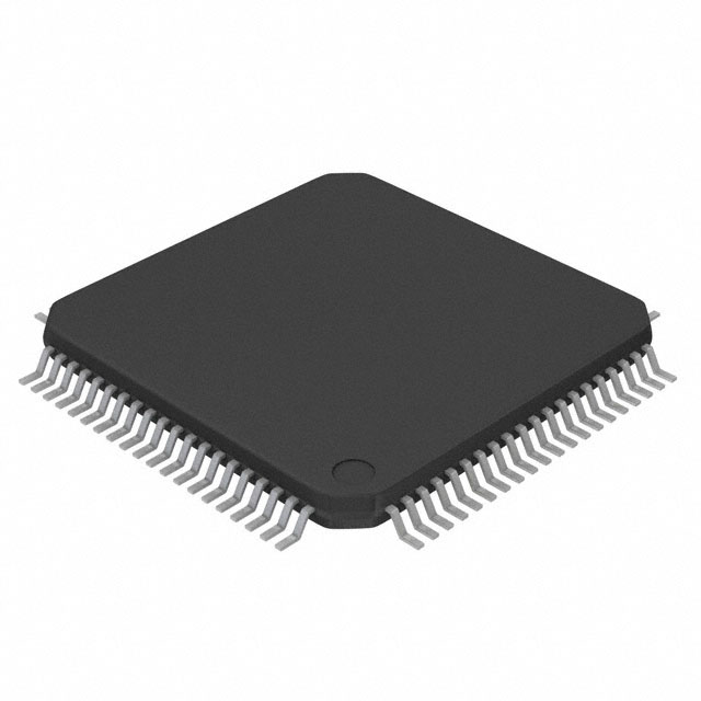
• Available in 64-Pin Quad Flat Pack (LQFP)
• For Complete Module Descriptions, See the
MSP430x4xx Family User's Guide
•
Energy Meters
Description
The TI MSP430™ family of ultra-low-power microcontrollers consists of several devices featuring different
sets of peripherals targeted for various applications. The architecture, combined with five low-power
modes, is optimized to achieve extended battery life in portable measurement applications. The device
features a powerful 16-bit RISC CPU, 16-bit registers, and constant generators that contribute to
maximum code efficiency. The digitally controlled oscillator (DCO) allows the device to wake up from lowpower modes to active mode in less than 6 µs.
The MSP430F42x series are microcontroller configurations with three independent 16-bit sigma-delta
ADCs, each with an integrated differential programmable gain amplifier input stage. Also included is a
built-in 16-bit timer, 128-segment LCD drive capability, hardware multiplier, and 14 I/O pins.
Typical applications include high-resolution applications such as handheld metering equipment, weigh
scales, and energy meters.
1
An IMPORTANT NOTICE at the end of this data sheet addresses availability, warranty, changes, use in safety-critical applications,
intellectual property matters and other important disclaimers. PRODUCTION DATA.
�MSP430F427, MSP430F425, MSP430F423
SLAS421B – APRIL 2004 – REVISED NOVEMBER 2016
www.ti.com
Device Information (1)
PACKAGE
BODY SIZE (2)
MSP430F427IPM
LQFP (64)
10 mm × 10 mm
MSP430F425IPM
LQFP (64)
10 mm × 10 mm
MSP430F423IPM
LQFP (64)
10 mm × 10 mm
PART NUMBER
(1)
(2)
1.4
For the most current part, package, and ordering information for all available devices, see the Package
Option Addendum in Section 8, or see the TI website at www.ti.com.
The sizes shown here are approximations. For the package dimensions with tolerances, see the
Mechanical Data in Section 8.
Functional Block Diagram
Figure 1-1 shows the functional block diagram.
XIN
DVCC
XOUT
DVSS
AVCC
AVSS
P1
P2
8
6
Port 1
Port 2
8 I/Os
Interrupt
Capability
6 I/Os
Interrupt
Capability
ACLK
Oscillators
FLL+
Flash
RAM
32KB
16KB
8KB
1KB
512 B
256 B
USART0
Timer_A3
SMCLK
MCLK
3 CC Reg
UART
or SPI
MAB
8-MHz
CPU
Including
16 Registers
MDB
Emulation
Module
JTAG
Interface
Hardware
Multiplier
MPY, MPYS,
MAC,MACS
POR,
SVS,
Brownout
Watchdog
WDT+
15 or 16 Bit
SD16
Three 16-Bit
SIgma-Delta
ADCs
Basic
Timer 1
1 Interrupt
Vector
LCD
128
Segments
1,2,3,4 MUX
fLCD
RST/NMI
Copyright © 2016, Texas Instruments Incorporated
Figure 1-1. MSP430F42x Block Diagram
2
Device Overview
Copyright © 2004–2016, Texas Instruments Incorporated
Submit Documentation Feedback
Product Folder Links: MSP430F427 MSP430F425 MSP430F423
�MSP430F427, MSP430F425, MSP430F423
www.ti.com
SLAS421B – APRIL 2004 – REVISED NOVEMBER 2016
Table of Contents
1
2
3
Device Overview ......................................... 1
5.20
SD16 Power Supply and Operating Characteristics 22
1.1
Features .............................................. 1
5.21
SD16 Analog Input Range .......................... 22
1.2
Applications ........................................... 1
5.22
SD16 Analog Performance.......................... 23
1.3
Description ............................................ 1
1.4
Functional Block Diagram ............................ 2
.................
...................
5.25 SD16 Built-in Reference Output Buffer .............
5.26 SD16 External Reference Input .....................
5.27 Flash Memory .......................................
5.28 JTAG Interface ......................................
5.29 JTAG Fuse .........................................
Detailed Description ...................................
6.1
CPU .................................................
6.2
Instruction Set .......................................
6.3
Operating Modes ....................................
6.4
Interrupt Vector Addresses..........................
6.5
Special Function Registers..........................
6.6
Memory Organization ...............................
6.7
Bootloader (BSL) ....................................
6.8
Flash Memory .......................................
6.9
Peripherals ..........................................
6.10 Input/Output Diagrams ..............................
Device and Documentation Support ...............
7.1
Getting Started and Next Steps .....................
7.2
Device Nomenclature ...............................
7.3
Tools and Software .................................
7.4
Documentation Support .............................
7.5
Related Links ........................................
7.6
Community Resources ..............................
7.7
Trademarks..........................................
7.8
Electrostatic Discharge Caution .....................
7.9
Export Control Notice ...............................
7.10 Glossary .............................................
Revision History ......................................... 4
Device Comparison ..................................... 5
3.1
4
Terminal Configuration and Functions .............. 6
.......................................... 6
4.2
Signal Descriptions ................................... 7
Specifications ........................................... 10
5.1
Absolute Maximum Ratings ........................ 10
5.2
ESD Ratings ........................................ 10
5.3
Recommended Operating Conditions ............... 10
4.1
5
Related Products ..................................... 5
5.4
5.5
5.6
5.7
5.8
5.9
5.10
5.11
5.12
5.13
5.14
5.15
5.16
5.17
5.18
5.19
Pin Diagram
6
Supply Current Into AVCC and DVCC Excluding
External Current .................................... 11
Thermal Resistance Characteristics, PM Package
(LQFP64) ............................................ 12
Schmitt-Trigger Inputs − Ports (P1 and P2),
RST/NMI, JTAG (TCK, TMS, TDI/TCLK,TDO/TDI) . 12
..............................
.............
Outputs − Ports (P1 and P2) ........................
Output Frequency ...................................
Typical Characteristics – Ports P1 and P2 ..........
Wake-up Time From LPM3 .........................
RAM .................................................
LCD..................................................
USART0 .............................................
POR, BOR ..........................................
SVS (Supply Voltage Supervisor and Monitor) .....
DCO .................................................
Crystal Oscillator, LFXT1 Oscillator ................
Inputs P1.x, P2.x, TAx
12
Leakage Current − Ports (P1 and P2)
12
7
13
13
14
15
15
15
15
16
17
19
21
8
5.23
SD16 Built-in Temperature Sensor
23
5.24
SD16 Built-in Voltage Reference
24
24
24
25
25
25
26
26
27
28
29
30
32
32
32
33
39
46
46
46
48
49
51
51
51
51
51
51
Mechanical, Packaging, and Orderable
Information .............................................. 52
Copyright © 2004–2016, Texas Instruments Incorporated
Submit Documentation Feedback
Product Folder Links: MSP430F427 MSP430F425 MSP430F423
Table of Contents
3
�MSP430F427, MSP430F425, MSP430F423
SLAS421B – APRIL 2004 – REVISED NOVEMBER 2016
www.ti.com
2 Revision History
NOTE: Page numbers for previous revisions may differ from page numbers in the current version.
Changes from June 2, 2007 to November 14, 2016
•
•
•
•
•
•
•
•
•
•
•
•
4
Page
Format and organization changes throughout document, including addition of section numbering ....................... 1
Added Section 3 ...................................................................................................................... 5
Added Section 5 and moved all electrical and timing specifications to it .................................................... 10
Added Section 5.2, ESD Ratings.................................................................................................. 10
Changed the MAX value of the I(LPM3) parameter at 85°C from 2.6 to 3.5 µA in Section 5.4, Supply Current Into
AVCC and DVCC Excluding External Current ..................................................................................... 11
Added Section 5.5, Thermal Resistance Characteristics, PM Package (LQFP-64) ........................................ 12
Changed all cases of "bootstrap loader" to "bootloader"....................................................................... 32
Changed all instances of Port/LCD to Port/LCD (added overline) ............................................................ 40
Changed the value of the Port/LCD column in Table 6-14, Port P1 (P1.2 to P1.7) Pin Functions ....................... 40
Changed the value of the Port/LCD column in Table 6-15, Port P2 (P2.0 and P2.1) Pin Functions ..................... 41
Added Section 7, Device and Documentation Support......................................................................... 46
Added Section 8, Mechanical, Packaging, and Orderable Information ...................................................... 52
Revision History
Copyright © 2004–2016, Texas Instruments Incorporated
Submit Documentation Feedback
Product Folder Links: MSP430F427 MSP430F425 MSP430F423
�MSP430F427, MSP430F425, MSP430F423
www.ti.com
SLAS421B – APRIL 2004 – REVISED NOVEMBER 2016
3 Device Comparison
Table 3-1 summarizes the available family members.
Table 3-1. Device Comparison (1) (2)
FLASH
(KB)
RAM
(B)
FREQUENCY
(MHz)
BSL
SD16
(CHANNELS)
I/Os
PACKAGE
MSP430F427
32
1K
8
UART
3
14
PM 64
MSP430F425
16
512
8
UART
3
14
PM 64
MSP430F423
8
256
8
UART
3
14
PM 64
DEVICE
(1)
(2)
3.1
For the most current package and ordering information, see the Package Option Addendum in Section 8, or see the TI website at
www.ti.com.
Package drawings, thermal data, and symbolization are available at www.ti.com/packaging.
Related Products
For information about other devices in this family of products or related products, see the following links.
TI Microcontrollers Product Selection TI's low-power and-high performance MCUs, with wired and
wireless connectivity options, are optimized for a broad range of applications.
Products for MSP430 Ultra-Low-Power Microcontrollers One platform. One ecosystem. Endless
possibilities. Enabling the connected world with innovations in ultra-low-power
microcontrollers with advanced peripherals for precise sensing and measurement.
Products for MSP430F2x/4x Ultra-Low-Power Microcontrollers
MSP430F2x/4x
microcontrollers
(MCUs) from the MSP ultra-low-power MCU series are general-purpose 16-bit
microcontrollers used for a wide range of applications including consumer electronics, data
logging applications, portable medical instruments, and low-power metering. MSP430F4x
MCUs feature an integrated LCD controller, while select MSP430F2x devices feature
extended temperature ranges.
Companion Products for MSP430F427 Review products that are frequently purchased or used with this
product.
Reference Designs The TI Designs Reference Design Library is a robust reference design library that
spans analog, embedded processor, and connectivity. Created by TI experts to help you
jump start your system design, all TI Designs include schematic or block diagrams, BOMs,
and design files to speed your time to market.
Copyright © 2004–2016, Texas Instruments Incorporated
Submit Documentation Feedback
Product Folder Links: MSP430F427 MSP430F425 MSP430F423
Device Comparison
5
�MSP430F427, MSP430F425, MSP430F423
SLAS421B – APRIL 2004 – REVISED NOVEMBER 2016
www.ti.com
4 Terminal Configuration and Functions
4.1
Pin Diagram
AVCC
DVSS
AVSS
P2.3/SVSIN
P2.4/UTXD0
P2.5/URXD0
RST/NMI
TCK
TMS
TDI/TCLK
TDO/TDI
P1.0/TA0
P1.1/TA0/MCLK
P1.2/TA1/S31
P1.3/SVSOUT/S30
P1.4/S29
Figure 4-1 shows the pinout for the 64-pin PM package.
64 63 62 61 60 59 58 57 56 55 54 53 52 51 50 49
DVCC
A0.0+
A0.0−
A1.0+
A1.0−
A2.0+
A2.0−
XIN
XOUT
VREF
P2.2/STE0
S0
S1
S2
S3
S4
48
47
46
45
44
43
42
41
40
39
38
37
36
35
2
3
4
5
6
7
8
9
10
11
12
13
14
15
34
33
P1.5/TACLK/ACLK/S28
P1.6/SIMO0/S27
P1.7/SOMI0/S26
P2.0/TA2/S25
P2.1/UCLK0/S24
R33
R23
R13
R03
COM3
COM2
COM1
COM0
S23
S22
S21
S5
S6
S7
S8
S9
S10
S11
S12
S13
S14
S15
S16
S17
S18
S19
S20
17 18 19 20 21 22 23 24 25 26 27 28 29 30 31 32
NOTE: TI recommends leaving all unused analog inputs open.
Figure 4-1. 64-Pin PM Package (Top View)
6
Terminal Configuration and Functions
Copyright © 2004–2016, Texas Instruments Incorporated
Submit Documentation Feedback
Product Folder Links: MSP430F427 MSP430F425 MSP430F423
�MSP430F427, MSP430F425, MSP430F423
www.ti.com
4.2
SLAS421B – APRIL 2004 – REVISED NOVEMBER 2016
Signal Descriptions
Table 4-1 describes the signals for all device variants
Table 4-1. Terminal Functions
SIGNAL NAME
PIN NO.
I/O
DESCRIPTION
DVCC
1
Digital supply voltage, positive terminal
A0.0+
2
I
Internal connection to SD16 channel 0, input 0 + (1)
A0.0−
3
I
Internal connection to SD16 channel 0, input 0 − (1)
A1.0+
4
I
Internal connection to SD16 channel 1, input 0 + (1)
A1.0−
5
I
Internal connection to SD16 channel 1, input 0 − (1)
A2.0+
6
I
Internal connection to SD16 channel 2, input 0 + (1)
A2.0−
7
I
Internal connection to SD16 channel 2, input 0 − (1)
XIN
8
I
Input port for crystal oscillator XT1. Standard or watch crystals can be connected.
XOUT
9
O
Output terminal of crystal oscillator XT1
VREF
10
I/O
Input for an external reference voltage, internal reference voltage output (can be used as
mid-voltage)
P2.2/STE0
11
I/O
General-purpose digital I/O
Slave transmit enable for USART0 in SPI mode
S0
12
O
LCD segment output 0
S1
13
O
LCD segment output 1
S2
14
O
LCD segment output 2
S3
15
O
LCD segment output 3
S4
16
O
LCD segment output 4
S5
17
O
LCD segment output 5
S6
18
O
LCD segment output 6
S7
19
O
LCD segment output 7
S8
20
O
LCD segment output 8
S9
21
O
LCD segment output 9
S10
22
O
LCD segment output 10
S11
23
O
LCD segment output 11
S12
24
O
LCD segment output 12
S13
25
O
LCD segment output 13
S14
26
O
LCD segment output 14
S15
27
O
LCD segment output 15
S16
28
O
LCD segment output 16
S17
29
O
LCD segment output 17
S18
30
O
LCD segment output 18
S19
31
O
LCD segment output 19
S20
32
O
LCD segment output 20
S21
33
O
LCD segment output 21
S22
34
O
LCD segment output 22
S23
35
O
LCD segment output 23
COM0
36
O
Common output, COM0−COM3 are used for LCD backplanes.
COM1
37
O
Common output, COM0−COM3 are used for LCD backplanes.
COM2
38
O
Common output, COM0−COM3 are used for LCD backplanes.
COM3
39
O
Common output, COM0−COM3 are used for LCD backplanes.
R03
40
I
Input port of fourth positive (lowest) analog LCD level (V5)
R13
41
I
Input port of third most positive analog LCD level (V4 or V3)
R23
42
I
Input port of second most positive analog LCD level (V2)
(1)
TI recommends open connection for all unused analog inputs.
Terminal Configuration and Functions
Submit Documentation Feedback
Product Folder Links: MSP430F427 MSP430F425 MSP430F423
Copyright © 2004–2016, Texas Instruments Incorporated
7
�MSP430F427, MSP430F425, MSP430F423
SLAS421B – APRIL 2004 – REVISED NOVEMBER 2016
www.ti.com
Table 4-1. Terminal Functions (continued)
SIGNAL NAME
R33
PIN NO.
I/O
43
O
DESCRIPTION
Output port of most positive analog LCD level (V1)
General-purpose digital I/O
P2.1/UCLK0/S24
44
I/O
External clock input for USART0 in UART or SPI mode or
clock output for USART0 in SPI mode
LCD segment output 24 (2)
General-purpose digital I/O
P2.0/TA2/S25
45
I/O
Timer_A Capture: CCI2A input, Compare: Out2 output
LCD segment output 25 (2)
General-purpose digital I/O
P1.7/SOMI0/S26
46
I/O
Slave out/master in for USART0 in SPI mode
LCD segment output 26 (2)
General-purpose digital I/O
P1.6/SIMO0/S27
47
I/O
Slave in/master out for USART0 in SPI mode
LCD segment output 27 (2)
General-purpose digital I/O
Timer_A and SD16 clock signal TACLK input
P1.5/TACLK/ACLK/S28
48
I/O
ACLK output (divided by 1, 2, 4, or 8)
LCD segment output 28 (2)
General-purpose digital I/O
P1.4/S29
49
I/O
LCD segment output 29 (2)
General-purpose digital I/O
P1.3/SVSOUT/S30
50
I/O
SVS: output of SVS comparator
LCD segment output 30 (2)
General-purpose digital I/O
P1.2/TA1/S31
51
I/O
Timer_A, Capture: CCI1A, CCI1B input, Compare: Out1 output
LCD segment output 31 (2)
General-purpose digital I/O
Timer_A, Capture: CCI0B input. Note: TA0 is only an input on this pin.
P1.1/TA0/MCLK
52
I/O
MCLK output
BSL receive
General-purpose digital I/O
P1.0/TA0
53
I/O
Timer_A, Capture: CCI0A input, Compare: Out0 output
BSL transmit
TDO/TDI
54
I/O
TDI/TCLK
55
I
Test data output port, TDO/TDI data output or programming data input terminal
Test data input or test clock input. The device protection fuse is connected to TDI.
TMS
56
I
Test mode select. TMS is used as an input port for device programming and test.
TCK
57
I
Test clock. TCK is the clock input port for device programming and test.
RST/NMI
58
I
Reset input
Nonmaskable interrupt input port
General-purpose digital I/O
P2.5/URXD0
59
I/O
Receive data in for USART0 in UART mode
General-purpose digital I/O
P2.4/UTXD0
60
I/O
Transmit data out for USART0 in UART mode
(2)
8
The LCD function is selected automatically when the applicable LCD module control bits are set, not with PxSEL bits.
Terminal Configuration and Functions
Copyright © 2004–2016, Texas Instruments Incorporated
Submit Documentation Feedback
Product Folder Links: MSP430F427 MSP430F425 MSP430F423
�MSP430F427, MSP430F425, MSP430F423
www.ti.com
SLAS421B – APRIL 2004 – REVISED NOVEMBER 2016
Table 4-1. Terminal Functions (continued)
SIGNAL NAME
PIN NO.
I/O
DESCRIPTION
General-purpose digital I/O
P2.3/SVSIN
61
I/O
Analog input to brownout, supply voltage supervisor
AVSS
62
Analog supply voltage, negative terminal. Supplies SD16, SVS, brownout, oscillator, and
LCD resistive divider circuitry.
DVSS
63
Digital supply voltage, negative terminal
AVCC
64
Analog supply voltage, positive terminal. Supplies SD16, SVS, brownout, oscillator, and
LCD resistive divider circuitry. Do not power up before DVCC.
Terminal Configuration and Functions
Submit Documentation Feedback
Product Folder Links: MSP430F427 MSP430F425 MSP430F423
Copyright © 2004–2016, Texas Instruments Incorporated
9
�MSP430F427, MSP430F425, MSP430F423
SLAS421B – APRIL 2004 – REVISED NOVEMBER 2016
www.ti.com
5 Specifications
Absolute Maximum Ratings (1)
5.1
over operating free-air temperature range (unless otherwise noted)
MIN
MAX
Voltage applied at VCC to VSS
–0.3
4.1
Voltage applied to any pin (2)
–0.3
VCC + 0.3
Diode current at any device terminal
(2)
V
V
±2
Storage temperature range, Tstg
(1)
UNIT
Unprogrammed device
–55
150
Programmed device
–40
85
mA
°C
Stresses beyond those listed under Absolute Maximum Ratings may cause permanent damage to the device. These are stress ratings
only, and functional operation of the device at these or any other conditions beyond those indicated under Recommended Operating
Conditions is not implied. Exposure to absolute-maximum-rated conditions for extended periods may affect device reliability.
All voltages referenced to VSS.The JTAG fuse-blow voltage, VFB, is allowed to exceed the absolute maximum rating. The voltage is
applied to the TDI/TCLK pin when blowing the JTAG fuse.
5.2
ESD Ratings
VALUE
V(ESD)
(1)
(2)
Electrostatic discharge
Human-body model (HBM), per ANSI/ESDA/JEDEC JS-001
(1)
UNIT
±1000
Charged-device model (CDM), per JEDEC specification JESD22-C101 (2)
V
±250
JEDEC document JEP155 states that 500-V HBM allows safe manufacturing with a standard ESD control process. Pins listed as
±1000 V may actually have higher performance.
JEDEC document JEP157 states that 250-V CDM allows safe manufacturing with a standard ESD control process. Pins listed as ±250 V
may actually have higher performance.
5.3
Recommended Operating Conditions
Typical values are specified at VCC = 3.3 V and TA = 25°C (unless otherwise noted)
MIN
Supply voltage during program
execution (1) (AVCC = DVCC = VCC)
VCC
VSS
Supply voltage (AVSS = DVSS = VSS)
TA
Operating free-air temperature range
f(LFXT1)
LFXT1 crystal frequency (3)
f(System)
Processor frequency (signal
MCLK) (also see Figure 5-1)
(1)
(2)
(3)
10
NOM
MAX
UNIT
SD16 disabled
1.8
3.6
SVS enabled, PORON = 1 (2), SD16 disabled
2.0
3.6
SD16 enabled or during programming of flash
memory
2.7
3.6
0
0
V
85
°C
450
8000
kHz
–40
LF selected, XTS_FLL = 0
Watch crystal
XT1 selected, XTS_FLL = 1
Ceramic resonator
XT1 selected, XTS_FLL = 1
Crystal
V
32.768
1000
8000
VCC = 1.8 V
DC
4.15
VCC = 3.6 V
DC
8
MHz
TI recommends powering AVCC and DVCC from the same source. A maximum difference of 0.3 V between AVCC and DVCC can be
tolerated during power up and operation.
The minimum operating supply voltage is defined according to the trip point where POR is going active by decreasing the supply
voltage. POR is going inactive when the supply voltage is raised above the minimum supply voltage plus the hysteresis of the SVS
circuitry.
In LF mode, the LFXT1 oscillator requires a watch crystal.
Specifications
Copyright © 2004–2016, Texas Instruments Incorporated
Submit Documentation Feedback
Product Folder Links: MSP430F427 MSP430F425 MSP430F423
�MSP430F427, MSP430F425, MSP430F423
www.ti.com
SLAS421B – APRIL 2004 – REVISED NOVEMBER 2016
fSystem − Maximum Processor Frequency − MHz
f (MHz)
Supply voltage range with SD16
enabled or during programming
of the flash memory
8 MHz
Supply voltage range
during program execution
6 MHz
4.15 MHz
1.8 V
2.7 V
3V
3.6 V
VCC − Supply Voltage − V
Figure 5-1. Frequency vs Supply Voltage
Supply Current Into AVCC and DVCC Excluding External Current (1)
5.4
over recommended operating free-air temperature range (unless otherwise noted)
TA
VCC
I(AM)
Active mode (AM)
f(MCLK) = f(SMCLK) = f(DCO) = 1 MHz,
f(ACLK) = 32768 Hz, XTS_FLL = 0,
program executes in flash
PARAMETER
–40°C to 85°C
I(LPM0)
Low-power mode 0 or 1 (LPM0 or LPM1) (2)
f(MCLK) = f(SMCLK) = f(DCO) = 1 MHz,
f(ACLK) = 32768 Hz, XTS_FLL = 0,
FN_8 = FN_4 = FN_3 = FN_2 = 0
I(LPM2)
Low-power mode 2 (LPM2) (2)
I(LPM3)
I(LPM4)
Low-power mode 3 (LPM3)
(2)
Low-power mode 4 (LPM4) (2)
TYP
MAX
UNIT
3V
400
500
µA
–40°C to 85°C
3V
130
150
µA
–40°C to 85°C
3V
10
22
µA
–40°C
1.5
2.0
25°C
1.6
2.1
1.7
2.2
85°C
2.0
3.5
–40°C
0.1
0.5
0.1
0.5
0.8
2.5
60°C
25°C
3V
3V
85°C
(1)
(2)
MIN
µA
µA
All inputs are tied to 0 V or VCC. Outputs do not source or sink any current. The current consumption in LPM2, LPM3, and LPM4 are
measured with active Basic Timer1 and LCD (ACLK selected). The current consumption of the SD16 and the SVS module are specified
in their respective sections. LPMx currents measured with WDT+ disabled. The currents are characterized with a KDS Daishinku DT-38
(6 pF) crystal.
Current consumption for brownout is included.
Current consumption of active mode versus system frequency:
I(AM) = I(AM) [at 1 MHz] × f(System) [MHz]
Current consumption of active mode versus supply voltage:
I(AM) = I(AM) [at 3 V] + 170 µA/V × (VCC – 3 V)
Copyright © 2004–2016, Texas Instruments Incorporated
Submit Documentation Feedback
Product Folder Links: MSP430F427 MSP430F425 MSP430F423
Specifications
11
�MSP430F427, MSP430F425, MSP430F423
SLAS421B – APRIL 2004 – REVISED NOVEMBER 2016
5.5
www.ti.com
Thermal Resistance Characteristics, PM Package (LQFP64)
VALUE
UNIT
RθJA
Junction-to-ambient thermal resistance, still air (1)
PARAMETER
55.7
°C/W
RθJC(TOP)
Junction-to-case (top) thermal resistance (2)
16.7
°C/W
RθJB
Junction-to-board thermal resistance (3)
27.1
°C/W
ΨJB
Junction-to-board thermal characterization parameter
26.8
°C/W
Junction-to-top thermal characterization parameter
0.8
°C/W
ΨJT
(1)
(2)
(3)
The junction-to-ambient thermal resistance under natural convection is obtained in a simulation on a JEDEC-standard, High-K board, as
specified in JESD51-7, in an environment described in JESD51-2a.
The junction-to-case (top) thermal resistance is obtained by simulating a cold plate test on the package top. No specific JEDECstandard test exists, but a close description can be found in the ANSI SEMI standard G30-88.
The junction-to-board thermal resistance is obtained by simulating in an environment with a ring cold plate fixture to control the PCB
temperature, as described in JESD51-8.
Schmitt-Trigger Inputs − Ports (P1 and P2), RST/NMI, JTAG (TCK, TMS,
TDI/TCLK,TDO/TDI)
5.6
over recommended operating free-air temperature range (unless otherwise noted)
VCC
MIN
MAX
UNIT
VIT+
Positive-going input threshold voltage
PARAMETER
3V
1.5
1.98
V
VIT-
Negative-going input threshold voltage
3V
0.9
1.3
V
Vhys
Input voltage hysteresis (VIT+ - VIT- )
3V
0.45
1
V
5.7
Inputs P1.x, P2.x, TAx
over recommended operating free-air temperature range (unless otherwise noted)
PARAMETER
TEST CONDITIONS
VCC
MIN
MAX
UNIT
1.5
cycle
50
ns
50
ns
t(int)
External interrupt timing
Port P1, P2: P1.x to P2.x, external trigger signal
for the interrupt flag (1)
t(cap)
Timer_A capture timing
TAx
3V
f(TAext)
Timer_A clock frequency externally
applied to pin
TAxCLK, INCLK t(H) = t(L)
3V
10
MHz
f(TAint)
Timer_A clock frequency
SMCLK or ACLK signal selected
3V
10
MHz
(1)
3V
The external signal sets the interrupt flag every time the minimum t(int) parameters are met. It may be set even with trigger signals
shorter than t(int). Both the cycle and timing specifications must be met to ensure the flag is set. t(int) is measured in MCLK cycles.
Leakage Current − Ports (P1 and P2) (1)
5.8
over recommended operating free-air temperature range (unless otherwise noted)
MAX
UNIT
Ilkg(P1.x)
Leakage current, Port P1.x
PARAMETER
Port 1: V(P1.x)
(2)
3V
±50
nA
Ilkg(P2.x)
Leakage current, Port P2.x
Port 2: V(P2.x)
(2)
3V
±50
nA
(1)
(2)
12
TEST CONDITIONS
VCC
MIN
The leakage current is measured with VSS or VCC applied to the corresponding pins, unless otherwise noted.
The port pin must be selected as input.
Specifications
Copyright © 2004–2016, Texas Instruments Incorporated
Submit Documentation Feedback
Product Folder Links: MSP430F427 MSP430F425 MSP430F423
�MSP430F427, MSP430F425, MSP430F423
www.ti.com
SLAS421B – APRIL 2004 – REVISED NOVEMBER 2016
Outputs − Ports (P1 and P2)
5.9
over recommended operating free-air temperature range (unless otherwise noted)
PARAMETER
TEST CONDITIONS
VOH
High-level output voltage
VOL
Low-level output voltage
(1)
(2)
IOH(max) = –1.5 mA
(1)
VCC
MIN
MAX
3V
VCC – 0.25
VCC
IOH(max) = –6 mA (2)
3V
VCC – 0.6
VCC
IOL(max) = 1.5 mA (1)
3V
VSS
VSS + 0.25
IOL(max) = 6 mA (2)
3V
VSS
VSS + 0.6
UNIT
V
V
The maximum total current, IOH(max) and IOL(max), for all outputs combined, should not exceed ±12 mA to satisfy the maximum specified
voltage drop.
The maximum total current, IOH(max) and IOL(max), for all outputs combined, should not exceed ±48 mA to satisfy the maximum specified
voltage drop.
5.10 Output Frequency
over recommended operating free-air temperature range (unless otherwise noted)
PARAMETER
f(Px.y)
TEST CONDITIONS
Output frequency
(1 ≤ × ≤ 2, 0 ≤ y ≤ 7)
CL = 20 F, IL = ±1.5 mA, VCC = 3 V
P1.1/TA0/MCLK,
P1.5/TACLK/ACLK/S28
CL = 20 pF, VCC = 3 V
MIN
TYP
DC
MAX
UNIT
12
MHz
12
MHz
f(ACLK),
f(MCLK),
f(SMCLK)
t(Xdc)
Duty cycle of output
frequency
P1.5/TACLK/ACLK/S28,
CL = 20 pF, VCC = 3 V
fACLK = fLFXT1 = fXT1
40%
fACLK = fLFXT1 = fLF
30%
fACLK = fLFXT1
P1.1/TA0/MCLK, CL = 20 pF, VCC = 3 V,
fMCLK = fDCOCLK
60%
70%
50%
50% –
15 ns
Copyright © 2004–2016, Texas Instruments Incorporated
Submit Documentation Feedback
Product Folder Links: MSP430F427 MSP430F425 MSP430F423
50%
50% +
15 ns
Specifications
13
�MSP430F427, MSP430F425, MSP430F423
SLAS421B – APRIL 2004 – REVISED NOVEMBER 2016
www.ti.com
5.11 Typical Characteristics – Ports P1 and P2
Figure 5-2 through Figure 5-5 show the typical output currents of Ports P1 and P2. One output loaded at a
time.
50
30
VCC = 3 V
P2.1
TA = 25°C
25
TA = 85°C
20
15
10
5
IOL − Typical Low-Level Output Current − mA
IOL − Typical Low-Level Output Current − mA
VCC = 2.2 V
P2.1
40
TA = 85°C
30
20
10
0
0
0.0
0.5
1.0
1.5
2.0
0.0
2.5
0.5
1.0
1.5
2.0
2.5
3.0
3.5
VOL − Low-Level Output Voltage − V
VOL − Low-Level Output Voltage − V
Figure 5-2. Typical Low-Level Output Current vs
Low-Level Output Voltage
Figure 5-3. Typical Low-Level Output Current vs
Low-Level Output Voltage
0
0
VCC = 2.2 V
P2.1
IOH − Typical High-Level Output Current − mA
IOH − Typical High-Level Output Current − mA
TA = 25°C
−5
−10
−15
TA = 85°C
−20
−25
TA = 25°C
VCC = 3 V
P2.1
−10
−20
−30
TA = 85°C
−40
TA = 25°C
−50
−30
0.0
0.5
1.0
1.5
2.0
2.5
VOH − High-Level Output Voltage − V
Figure 5-4. Typical High-Level Output Current vs
High-Level Output Voltage
14
Specifications
0.0
0.5
1.0
1.5
2.0
2.5
3.0
3.5
VOH − High-Level Output Voltage − V
Figure 5-5. Typical High-Level Output Current vs
High-Level Output Voltage
Copyright © 2004–2016, Texas Instruments Incorporated
Submit Documentation Feedback
Product Folder Links: MSP430F427 MSP430F425 MSP430F423
�MSP430F427, MSP430F425, MSP430F423
www.ti.com
SLAS421B – APRIL 2004 – REVISED NOVEMBER 2016
5.12 Wake-up Time From LPM3
over recommended operating free-air temperature range (unless otherwise noted)
PARAMETER
TEST CONDITIONS
MIN
f = 1 MHz
td(LPM3)
Delay time
f = 2 MHz
MAX
UNIT
6
VCC = 3 V
6
f = 3 MHz
µs
6
5.13 RAM
over recommended operating free-air temperature range (unless otherwise noted)
PARAMETER
TEST CONDITIONS
(1)
MIN
CPU halted (1)
VRAMh
MAX
1.6
UNIT
V
This parameter defines the minimum supply voltage when the data in program memory RAM remain unchanged. No program execution
should take place during this supply voltage condition.
5.14 LCD
over recommended operating free-air temperature range (unless otherwise noted)
PARAMETER
V(33)
TEST CONDITIONS
V(23)
VCC = 3 V
V(13)
Voltage at R13
V(33) – V(03)
Voltage at R33 to R03
R03 = VSS
Input leakage
I(R23)
R23 = 2 × VCC / 3
2.5
±20
±20
V(03)
V(03) – 0.1
V(13)
V(13) – 0.1
V(23)
V(23) – 0.1
V(33)
V(33) + 0.1
I(Sxx) = –3 µA, VCC = 3 V
V(Sxx3)
nA
±20
V(Sxx1)
Segment line voltage
V
VCC + 0.2
V(Sxx0)
V(Sxx2)
UNIT
[V(33) – V(03)] ×
1/3 + V(03)
No load at all
segment and
common lines,
VCC = 3 V
R13 = VCC / 3
MAX
VCC + 0.2
[V(33) – V(03)] ×
2/3 + V(03)
Voltage at R23
I(R03)
TYP
2.5
Analog voltage
I(R13)
MIN
Voltage at R33
V
5.15 USART0 (1)
over recommended operating free-air temperature range (unless otherwise noted)
PARAMETER
t(τ)
(1)
USART0 deglitch time
TEST CONDITIONS
VCC = 3 V, SYNC = 0, UART mode
MIN
TYP
MAX
UNIT
150
280
500
ns
The signal applied to the USART0 receive signal/terminal (URXD0) should meet the timing requirements of t(τ) to ensure that the URXS
flip-flop is set. The URXS flip-flop is set with negative pulses meeting the minimum-timing condition of t(τ). The operating conditions to
set the flag must be met independently from this timing constraint. The deglitch circuitry is active only on negative transitions on the
URXD0 line.
Copyright © 2004–2016, Texas Instruments Incorporated
Submit Documentation Feedback
Product Folder Links: MSP430F427 MSP430F425 MSP430F423
Specifications
15
�MSP430F427, MSP430F425, MSP430F423
SLAS421B – APRIL 2004 – REVISED NOVEMBER 2016
www.ti.com
5.16 POR, BOR (1)
over recommended operating free-air temperature range (unless otherwise noted)
PARAMETER
TEST CONDITIONS
MIN
TYP
td(BOR)
Brownout (2)
V(B_IT–)
dVCC/dt ≤ 3 V/s (see Figure 5-6 through Figure 5-8)
dVCC/dt ≤ 3 V/s (see Figure 5-6)
t(reset)
Pulse duration needed at RST/NMI pin to accept
reset internally, VCC = 3 V
(2)
2000
µs
V
V(B_IT– )
Vhys(B_IT–)
(1)
UNIT
0.7 ×
dVCC/dt ≤ 3 V/s (see Figure 5-6)
VCC(start)
MAX
70
130
1.71
V
180
mV
2
µs
The current consumption of the brownout module is already included in the ICC current consumption data. The voltage level V(B_IT–) +
Vhys(B_IT–) ≤ 1.8 V.
During power up, the CPU begins code execution following a period of td(BOR) after VCC = V(B_IT–)+ Vhys(B_IT–). The default FLL+ settings
must not be changed until VCC ≥ VCC(min), where VCC(min) is the minimum supply voltage for the desired operating frequency. See the
MSP430x4xx Family User's Guide for more information on the brownout and SVS circuit.
VCC
Vhys(B_IT−)
V(B_IT−)
VCC(start)
1
0
td(BOR)
Figure 5-6. POR and BOR vs Supply Voltage
VCC
2
VCC = 3 V
Typical Conditions
tpw
3V
VCC(drop) − V
1.5
1
VCC(drop)
0.5
0
0.001
1
1000
tpw − Pulse Width − µs
1 ns
1 ns
tpw − Pulse Width − µs
Figure 5-7. VCC(drop) Level With a Rectangular Voltage Drop to Generate a POR or BOR Signal
16
Specifications
Copyright © 2004–2016, Texas Instruments Incorporated
Submit Documentation Feedback
Product Folder Links: MSP430F427 MSP430F425 MSP430F423
�MSP430F427, MSP430F425, MSP430F423
www.ti.com
SLAS421B – APRIL 2004 – REVISED NOVEMBER 2016
VCC
2
tpw
3V
VCC = 3 V
Typical Conditions
VCC(drop) − V
1.5
1
VCC(drop)
0.5
tf = tr
0
0.001
1
tf
1000
tpw − Pulse Width − µs
tr
tpw − Pulse Width − µs
Figure 5-8. VCC(drop) Level With a Triangular Voltage Drop to Generate a POR or BOR Signal
5.17 SVS (Supply Voltage Supervisor and Monitor) (1)
over recommended operating free-air temperature range (unless otherwise noted) (also see Figure 5-10)
PARAMETER
t(SVSR)
TEST CONDITIONS
MIN
dVCC/dt > 30 V/ms (see Figure 5-9)
SVS on, switch from VLD = 0 to VLD ≠ 0, VCC = 3 V
tsettle
VLD ≠ 0 (2)
V(SVSstart)
VLD ≠ 0, VCC/dt ≤ 3 V/s (see Figure 5-9)
2000
20
1.55
VLD = 1
VCC/dt ≤ 3 V/s (see Figure 5-9)
Vhys(SVS_IT–)
VCC/dt ≤ 3 V/s (see Figure 5-9), external voltage
applied on P2.3
VCC/dt ≤ 3 V/s (see Figure 5-9)
V(SVS_IT–)
VCC/dt ≤ 3 V/s (see Figure 5-9), external voltage
applied on P2.3
(1)
(2)
(3)
MAX
150
dVCC/dt ≤ 30 V/ms
td(SVSon)
ICC(SVS) (1)
TYP
5
VLD = 2 to 14
VLD = 15
70
120
µs
12
µs
1.7
V
155
mV
V(SVS_IT–)
× 0.008
4.4
10.4
VLD = 1
1.8
1.9
2.05
VLD = 2
1.94
2.1
2.25
VLD = 3
2.05
2.2
2.37
VLD = 4
2.14
2.3
2.48
VLD = 5
2.24
2.4
2.6
VLD = 6
2.33
2.5
2.71
VLD = 7
2.46
2.65
2.86
VLD = 8
2.58
2.8
3
VLD = 9
2.69
2.9
3.13
VLD = 10
2.83
3.05
3.29
VLD = 11
2.94
3.2
3.42
VLD = 12
3.11
3.35
3.61 (3)
VLD = 13
3.24
3.5
3.76 (3)
VLD = 14
3.43
(3)
3.99 (3)
VLD = 15
1.1
1.2
1.3
10
15
VLD ≠ 0, VCC = 2.2 V or 3 V
µs
150
V(SVS_IT–)
× 0.004
3.7
UNIT
mV
V
µA
The current consumption of the SVS module is not included in the ICC current consumption data.
tsettle is the settling time that the comparator o/p must have a stable level after VLD is switched from VLD ≠ 0 to a different VLD value
between 2 and 15. The overdrive is assumed to be greater than 50 mV.
The recommended operating voltage range is limited to 3.6 V.
Copyright © 2004–2016, Texas Instruments Incorporated
Submit Documentation Feedback
Product Folder Links: MSP430F427 MSP430F425 MSP430F423
Specifications
17
�MSP430F427, MSP430F425, MSP430F423
SLAS421B – APRIL 2004 – REVISED NOVEMBER 2016
Software Sets VLD > 0:
SVS is Active
VCC
V
www.ti.com
V hys(SVS_IT−)
(SVS_IT−)
V(SVSstart)
V hys(B_IT−)
V(B_IT−)
VCC(start)
Brownout
Region
Brownout
Region
Brownout
1
0
t d(BOR)
SVS out
t d(BOR)
SVS Circuit is Active From VLD > to VCC < V(B_IT−)
1
0
t d(SVSon)
Set POR
1
t d(SVSR)
Undefined
0
Figure 5-9. SVS Reset (SVSR) vs Supply Voltage
VCC
t pw
3V
2
Rectangular Drop
1.5
VCC(drop)
V CC(drop) − V
Triangular Drop
1
1 ns
0.5
1 ns
VCC
t pw
3V
0
1
10
100
1000
t pw − Pulse Width − µs
VCC(drop)
tr = tf
tf
tr
t − Pulse Width − µs
Figure 5-10. VCC(drop) With a Rectangular Voltage Drop and a Triangular Voltage Drop to Generate an SVS
Signal
18
Specifications
Copyright © 2004–2016, Texas Instruments Incorporated
Submit Documentation Feedback
Product Folder Links: MSP430F427 MSP430F425 MSP430F423
�MSP430F427, MSP430F425, MSP430F423
www.ti.com
SLAS421B – APRIL 2004 – REVISED NOVEMBER 2016
5.18 DCO
over recommended operating free-air temperature range (unless otherwise noted) (see Figure 5-11 through Figure 5-13)
PARAMETER
TEST CONDITIONS
VCC
MIN
TYP
MAX
UNIT
f(DCOCLK)
N(DCO) = 01Eh, FN_8 = FN_4 = FN_3 = FN_2 = 0, D = 2,
DCOPLUS = 0, fCrystal = 32.768 kHz
3V
f(DCO = 2)
FN_8 = FN_4 = FN_3 = FN_2 = 0, DCOPLUS = 1
3V
0.3
0.7
1.3
MHz
f(DCO = 27)
FN_8 = FN_4 = FN_3 = FN_2 = 0, DCOPLUS = 1
3V
2.7
6.1
11.3
MHz
f(DCO = 2)
FN_8 = FN_4 = FN_3 = FN_2 = 1, DCOPLUS = 1
3V
0.8
1.5
2.5
MHz
f(DCO = 27)
FN_8 = FN_4 = FN_3 = FN_2 = 1, DCOPLUS = 1
3V
6.5
12.1
20
MHz
f(DCO = 2)
FN_8 = FN_4 = 0, FN_3 = 1, FN_2 = x, DCOPLUS = 1
3V
1.3
2.2
3.5
MHz
f(DCO = 27)
FN_8 = FN_4 = 0, FN_3 = 1, FN_2 = x, DCOPLUS = 1
3V
10.3
17.9
28.5
MHz
f(DCO = 2)
FN_8 = 0, FN_4 = 1, FN_3 = FN_2 = x, DCOPLUS = 1
3V
2.1
3.4
5.2
MHz
f(DCO = 27)
FN_8 = 0, FN_4 = 1, FN_3 = FN_2 = x, DCOPLUS = 1
3V
16
26.6
41
MHz
f(DCO = 2)
FN_8 = 1, FN_4 = 1 = FN_3 = FN_2 = x, DCOPLUS = 1
3V
4.2
6.3
9.2
MHz
f(DCO = 27)
FN_8 = 1, FN_4 = 1 = FN_3 = FN_2 = x, DCOPLUS = 1
30
46
70
MHz
Sn
Step size (ratio) between adjacent DCO taps:
Sn = fDCO(Tap n+1)/fDCO(Tap n) (see Figure 5-12 for taps 21 to 27)
Dt
Temperature drift, N(DCO) = 01Eh, FN_8 = FN_4 = FN_3 =
FN_2 = 0, D = 2, DCOPLUS = 0
DV
Drift with VCC variation, N(DCO) = 01Eh, FN_8 = FN_4 = FN_3
= FN_2 = 0, D = 2, DCOPLUS = 0
1
3V
MHz
1 < TAP ≤ 20
1.06
1.11
TAP = 27
1.07
1.17
3V
–0.2
–0.3
–0.4
%/°C
0
5
15
%/V
f(DCO)
f(DCO)
f(DCO3V)
f(DCO20°C)
1.0
1.0
0
1.8
2.4
3.0
3.6
−40
−20
0
20
40
60
85
VCC − V
TA – °C
Figure 5-11. DCO Frequency vs Supply Voltage (VCC) and vs Ambient Temperature
Copyright © 2004–2016, Texas Instruments Incorporated
Submit Documentation Feedback
Product Folder Links: MSP430F427 MSP430F425 MSP430F423
Specifications
19
�MSP430F427, MSP430F425, MSP430F423
Sn – Step-Size Ratio Between DCO Taps
SLAS421B – APRIL 2004 – REVISED NOVEMBER 2016
www.ti.com
1.17
Max
1.11
1.07
1.06
Min
1
20
27
DCO Tap
Figure 5-12. DCO Tap Step Size
f (DCO)
Legend
Tolerance at Tap 27
DCO Frequency
Adjusted by Bits
29 to 25 in SCFI1 {N {DCO} }
Tolerance at Tap 2
Overlapping DCO Ranges:
Uninterrupted Frequency Range
FN_2 = 0
FN_3 = 0
FN_4 = 0
FN_8 = 0
FN_2 = 1
FN_3 = 0
FN_4 = 0
FN_8 = 0
FN_2 = x
FN_3 = 1
FN_4 = 0
FN_8 = 0
FN_2 = x
FN_3 = x
FN_4 = 1
FN_8 = 0
FN_2 = x
FN_3 = x
FN_4 = x
FN_8 = 1
Figure 5-13. Five Overlapping DCO Ranges Controlled by FN_x Bits
20
Specifications
Copyright © 2004–2016, Texas Instruments Incorporated
Submit Documentation Feedback
Product Folder Links: MSP430F427 MSP430F425 MSP430F423
�MSP430F427, MSP430F425, MSP430F423
www.ti.com
SLAS421B – APRIL 2004 – REVISED NOVEMBER 2016
5.19 Crystal Oscillator, LFXT1 Oscillator (1)
(2)
over recommended operating free-air temperature range (unless otherwise noted)
PARAMETER
CXIN
TEST CONDITIONS
Integrated input capacitance (3)
VCC
MIN
OSCCAPx = 0h
0
OSCCAPx = 1h
10
OSCCAPx = 2h
3V
0
OSCCAPx = 1h
10
3V
VIH
(1)
(2)
(3)
(4)
Input levels at XIN (4)
pF
pF
14
OSCCAPx = 3h
VIL
UNIT
18
OSCCAPx = 0h
OSCCAPx = 2h
MAX
14
OSCCAPx = 3h
CXOUT Integrated output capacitance (3)
TYP
18
3V
VSS
0.2 × VCC
0.8 × VCC
VCC
V
The parasitic capacitance from the package and board may be estimated to be 2 pF. The effective load capacitor for the crystal is
(CXIN × CXOUT) / (CXIN + CXOUT). This is independent of XTS_FLL.
To improve EMI on the low-power LFXT1 oscillator, particularly in the LF mode (32 kHz), the following guidelines should be observed.
• Keep the trace between the device and the crystal as short as possible.
• Design a good ground plane around the oscillator pins.
• Prevent crosstalk from other clock or data lines into oscillator pins XIN and XOUT.
• Avoid running PCB traces underneath or adjacent to the XIN and XOUT pins.
• Use assembly materials and processes that avoid any parasitic load on the oscillator XIN and XOUT pins.
• If conformal coating is used, ensure that it does not induce capacitive or resistive leakage between the oscillator pins.
• Do not route the XOUT line to the JTAG header to support the serial programming adapter as shown in other documentation. This
signal is no longer required for the serial programming adapter.
TI recommends external capacitance for precision real-time clock applications; OSCCAPx = 0h.
Applies only when using an external logic-level clock source. XTS_FLL must be set. Not applicable when using a crystal or resonator.
Copyright © 2004–2016, Texas Instruments Incorporated
Submit Documentation Feedback
Product Folder Links: MSP430F427 MSP430F425 MSP430F423
Specifications
21
�MSP430F427, MSP430F425, MSP430F423
SLAS421B – APRIL 2004 – REVISED NOVEMBER 2016
www.ti.com
5.20 SD16 Power Supply and Operating Characteristics
over recommended operating free-air temperature range (unless otherwise noted)
PARAMETER
AVCC
ISD16
fSD16
TEST CONDITIONS
Analog supply voltage
VCC
AVCC = DVCC, AVSS = DVSS = 0 V
Analog supply current: 1 active SD16
channel including internal reference
Analog front-end input clock frequency
SD16LP = 0,
fSD16 = 1 MHz,
SD16OSR = 256
SD16LP = 1,
fSD16 = 0.5 MHz,
SD16OSR = 256
MIN
TYP
MAX
650
950
2.7
GAIN: 1, 2
GAIN: 4, 8, 16
3.6
730
1100
1050
1550
GAIN: 1
620
930
GAIN: 32
700
1060
GAIN: 32
3V
SD16LP = 0 (low-power mode disabled)
1
SD16LP = 1 (low-power mode enabled)
0.5
UNIT
V
µA
MHz
5.21 SD16 Analog Input Range (1)
over operating free-air temperature range (unless otherwise noted)
PARAMETER
VID
TEST CONDITIONS
Differential input voltage range for
specified performance (2)
VCC
MIN
TYP
SD16GAINx = 1, SD16REFON = 1
±500
SD16GAINx = 2, SD16REFON = 1
±250
SD16GAINx = 4, SD16REFON = 1
±125
SD16GAINx = 8, SD16REFON = 1
±62
SD16GAINx = 16, SD16REFON = 1
±31
SD16GAINx = 32, SD16REFON = 1
±15
MAX
UNIT
mV
ZI
Input impedance
(one input pin to AVSS)
fSD16 = 1 MHz, SD16GAINx = 1
ZID
Differential input impedance
(IN+ to IN−)
fSD16 = 1 MHz, SD16GAINx = 1
VI
Absolute input voltage range
AVSS –
1
AVCC
V
VIC
Common-mode input voltage range
AVSS –
1
AVCC
V
(1)
(2)
22
fSD16 = 1 MHz, SD16GAINx = 32
fSD16 = 1 MHz, SD16GAINx = 32
200
3V
3V
kΩ
75
300
400
100
150
kΩ
All parameters pertain to each SD16 channel.
The analog input range depends on the reference voltage applied to VREF. If VREF is sourced externally, the full-scale range is defined
by VFSR+ = +(VREF / 2) / GAIN and VFSR− = −(VREF / 2) / GAIN. The analog input range should not exceed 80% of VFSR+ or VFSR−.
Specifications
Copyright © 2004–2016, Texas Instruments Incorporated
Submit Documentation Feedback
Product Folder Links: MSP430F427 MSP430F425 MSP430F423
�MSP430F427, MSP430F425, MSP430F423
www.ti.com
SLAS421B – APRIL 2004 – REVISED NOVEMBER 2016
5.22 SD16 Analog Performance
fSD16 = 1 MHz, SD16OSRx = 256, SD16REFON = 1, over operating free-air temperature range (unless otherwise noted)
PARAMETER
SINAD
G
Signal-to-noise +
distortion ratio
Nominal gain
EOS
Offset error
dEOS/dT
Offset error
temperature
coefficient
CMRR
Common-mode
rejection ratio
AC PSRR
AC power-supply
rejection ratio
XT
Crosstalk
TEST CONDITIONS
MIN
TYP
SD16GAINx = 1, signal amplitude = 500 mV
83.5
85
SD16GAINx = 2, signal amplitude = 250 mV
81.5
84
SD16GAINx = 4, signal amplitude = 125 mV
76
79.5
73
76.5
SD16GAINx = 16, signal amplitude = 31 mV
69
73
SD16GAINx = 32, signal amplitude = 15 mV
62
69
SD16GAINx = 1
0.97
1.00
1.02
SD16GAINx = 2
1.90
1.96
2.02
SD16GAINx = 4
3.76
3.86
3.96
7.36
7.62
7.84
SD16GAINx = 16
14.56
15.04
15.52
SD16GAINx = 32
27.20
28.35
29.76
SD16GAINx = 8, signal amplitude = 62 mV
VCC
fIN = 50 Hz
or 100 Hz
3V
3V
SD16GAINx = 8
SD16GAINx = 1
±1.5
SD16GAINx = 1
±4
3V
SD16GAINx = 32
SD16GAINx = 1, Common-mode input signal:
VID = 500 mV, fIN = 50 Hz or 100 Hz
SD16GAINx = 32, Common-mode input signal:
VID = 16 mV, fIN = 50 Hz or 100 Hz
SD16GAINx = 1, VCC = 3 V ±100 mV, fVCC = 50 Hz
±20
UNIT
dB
±0.2
3V
SD16GAINx = 32
MAX
%FSR
±20
ppm
±100 FSR/°C
>90
3V
dB
>75
3V
>80
dB
3V


 工商网监
湘ICP备2023018690号
工商网监
湘ICP备2023018690号