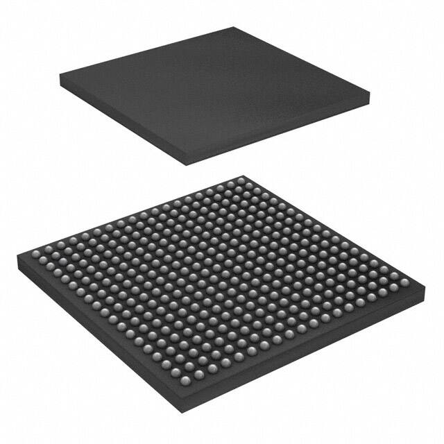
Product
Folder
Sample &
Buy
Technical
Documents
Tools &
Software
Support &
Community
TMS570LS3137-EP
ZHCSBS0C – OCTOBER 2013 – REVISED JANUARY 2015
TMS570LS3137-EP 16 位和 32 位 RISC 闪存微控制器
1 器件概述
1.1
特性
1
• 用于安全关键型应用的高性能微控制器
– 运行在锁步中的双中央处理单元 (CPU)
– 闪存和 RAM 接口上的 ECC
– 内置 CPU 和片上 RAM 自检
– 带有错误引脚的错误信令模块
– 电压和时钟监视
• ARM® Cortex™ – R4F 32 位 RISC CPU
– 带有 8 级管线的高效 1.66DMIPS/MHz
– 支持单精度和双精度的浮点运算单元 (FPU)
– 12 区域内存保护单元
– 带有第三方支持的开放式架构
• 运行条件
– 高达180MHz 系统时钟
– 内核电源电压 (VCC):标称值 1.2V
– I/O 电源电压 (VCCOI):标称值 3.3V
– ADC 电源电压 (VCCAD): 3.0 至 5.25V
– 采用 IP 模块门级设计,工作温度范围为 -40°C
至 125°C,仅包含闪存,MibADC 定时
器,nPORRST、N2HET 和 FlexRay
• 集成存储器
– 支持 ECC 的 3MB 程序闪存
– 256KB 且支持 ECC 的 RAM
– 支持 ECC、用于仿真 EERPOM 的 64KB 闪存
• 16 位外部存储器接口
• 通用平台架构
– 系列间一致的存储器映射
– 实时中断定时器 (RTI) 操作系统 (OS) 定时器
– 96 通道矢量中断模块 (VIM)
– 2 通道循环冗余校验器 (CRC)
• 直接内存访问 (DMA) 控制器
– 16 通道和 32 控制数据包
– 针对控制数据包 RAM 的奇偶校验保护
– 由专用 MPU 保护的 DMA 访问
• 带有内置跳周检测器的调频锁相环 (FMPLL)
• 独立的非调制 PLL
• IEEE 1149.1 JTAG,边界扫描和 ARM CoreSight™
组件
• JTAG 安全模块
• 跟踪和校准功能
– 嵌入式跟踪宏单元 (ETM-R4)
– 数据修改模块 (DMM)
– RAM 跟踪端口 (RTP)
– 参数覆盖模块 (POM)
• 多通信接口
– 10/100Mbps 以太网 MAC (EMAC)
• 符合 IEEE 802.3 标准(只适用于 3.3V I/O)
• 支持媒介独立接口 (MII),精简媒介独立接口
(RMII) 和管理数据输入输出 (MDIO)
– 带有 2 个通道的 FlexRay 控制器
• 带有奇偶检验保护的 8KB 消息 RAM
• 专用传输单元 (FTU)
– 3 个 CAN 控制器 (DCAN)
• 64 个邮箱,每个邮箱均具有奇偶校验保护
• 与 CAN 协议 2.0B 版兼容
– 本地互连网络 (LIN) 接口控制器
• 与 LIN 协议版本 2.1 兼容
• 可被配置为第二个 SCI
– 标准串行通信接口 (SCI)
– 内部集成电路 (I2C)
– 3 个多通道经缓冲串行外设接口 (MibSPI)
• 128 个字,每个字具有奇偶校验保护
– 2 个标准串行外设接口 (SPI)
• 2 个高端定时器模块 (N2HET)
– N2HET1:32 个 可编程通道
– N2HET2:18 个可编程通道
– 160 个字指令 RAM,每个都带有奇偶校验保护
– 每个 N2HET 包括硬件角发生器
– 针对每个 N2HET (HTU) 的具有 MPU 的专用传
输单元
• 2 个 10 或 12 位多通道经缓冲 ADC 模块
– ADC1:24 个通道
– ADC2:与 ADC1 共用的 16 个通道
– 64 个结果缓冲器,每个缓冲器具有奇偶校验保护
• 16 个能够生成中断的通用输入/输出引脚 (GPIO)
• 封装
– 337 球状引脚栅格阵列 (SnPb)(GWT)
1
PRODUCTION DATA information is current as of publication date. Products conform to specifications per the terms of the Texas
Instruments standard warranty. Production processing does not necessarily include testing of all parameters.
English Data Sheet: SPNS230
�TMS570LS3137-EP
ZHCSBS0C – OCTOBER 2013 – REVISED JANUARY 2015
1.2
•
•
•
•
•
•
•
•
应用范围
刹车系统(防抱死制动系统和电子稳定性控制)
电动助力转向
混合动力汽车 (HEV) 和电动汽车 (EV) 反向器系统
电池管理系统
主动驾驶员辅助系统
航天和航空电子设备
轨道交通
越野车
1.3
www.ti.com.cn
•
支持国防、航天和医疗应用
– 受控基线
– 同一组装和测试场所
– 同一制造场所
– 支持温度范围 –55°C 至 125°C
– 延长的产品生命周期
– 延长的产品变更通知
– 产品可追溯性
说明
TMS570LS3137-EP 器件是一款用于安全系统的高性能 系列微控制器。 此安全架构包括:
• 以锁步模式运行的双核 CPU
• CPU 和内存内置自检 (BIST) 逻辑
• 闪存和数据 SRAM 上的 ECC
• 外设存储器的奇偶校验
• 外设 I/O 上的回路功能
TMS570LS3137-EP 器件集成了 ARM Cortex-R4F 浮点 CPU,此 CPU 可提供一个高效的 1.66
DMIPS/MHz,并且 具有能够以高达 180 MHz 运行的配置,从而提供高达 298 DMIPS。 此器件支持字不变
大端序 [BE32] 格式。
TMS570LS3137-EP 器件具有 3MB 的集成闪存以及 256KB 的数据 RAM,这些闪存和 RAM 支持单位错误
校正和双位错误检测。 这个器件上的闪存存储器是一个由 64 位宽数据总线接口实现的非易失性、电可擦除
并且可编程的存储器。 为了实现所有读取、编程和擦除操作,此闪存运行在一个 3.3V 电源输入上(与 I/O
电源一样的电平)。 当处于管线模式中时,闪存可在高达 180MHz 的系统时钟频率下运行。 在字节、半
字、字和双字模式中,SRAM 支持单循环读取和写入访问。
TMS570LS3137-EP 器件特有针对基于实时控制应用的外设,其中包括 2 个下一代高端定时器 (N2HET) 时
序协处理器和 2 个支持多达 24 个输入的 12 位模数转换器 (ADC) 。
N2HET1 是一款高级智能定时器,此定时器能够为实时应用提供精密的计时功能。 该定时器为软件控制
型,采用一个精简指令集,并具有一个专用的定时器微级机和一个连接的 I/O 端口。 N2HET 可被用于脉宽
调制输出,捕捉或比较输入,GPIO。 N2HET 特别适合于要求多个传感器信息并且用复杂和准确时间脉冲来
驱动致动器的应用。 一个高端定时器传输单元 (HTU) 能够执行 DMA 类型处理来与主存储器之间传输
N2HET 数据。 一个内存保护单元 (MPU) 被内置于 HTU 内。
此器件具有 2 个 12 位分辨率 MibADC,每个 MibADC 具有 24 个通道和受 64 字奇偶校验保护的缓冲器
RAM。 MibADC 通道可被独立转换或者可针对顺序转换序列由软件成组。 16 个通道可在两个 MibADC 间
共用。 有三个独立的组。 当被触发或者针对连续转换模式进行配置后,每个序列可被转换一次。
此器件有多个通信接口:3 个 MibSPI,,1 个 LIN,1 个SCI,3 个 DACN,1 个 I2C。 SPI 为相似移位寄存
器类型器件之间串行高速通信的提供了一个便捷方法。 LIN 支持本地互联标准 2.0 并可被用作一个使用标准
不归零码 (NRZ) 格式的全双工模式 UART。
DCAN 支持 CAN 2.0(A 和 B)协议标准并使用一个串行、多主控通信协议,此协议用高达 1Mbps 的稳健
耐用通信速率有效支持分布式实时控制。 DCAN 非常适合于工作于嘈杂和恶劣环境中的系统(例如,汽车
网络互连和工业领域),此类系统需要可靠的串行通信或多路复用布线。
I2C 模块是一个多主控通信模块,此模块通过 I2C 串行总线在微控制器和一个 I2C 兼容器件之间提供一个接
口。 此 I2C 支持 100Kbps 和 400Kbps 的速度。
此调频锁相环 (FMPLL) 时钟模块被用来将外部频率基准与一个内部使用的更高频率相乘。 这个器件上有两
个 FMPLL 模块。 当被启用时,这些模块提供 7 个可能的时钟源中的两个到全局时钟模块 (GCM)。 此
GCM 管理可用时钟源与器件时钟域间的映射。
2
器件概述
版权 © 2013–2015, Texas Instruments Incorporated
�TMS570LS3137-EP
www.ti.com.cn
ZHCSBS0C – OCTOBER 2013 – REVISED JANUARY 2015
此器件还有一个外部时钟前置分频器 (ECP) 模块,当被启用时,此模块在 ECLK 引脚/焊球上输出一个连续
外部时钟。 ECLK 频率是一个外设接口时钟 (VCLK) 频率的用户可编程比例。 这个可被外部监视的低频输出
作为此器件运行频率的指示器。
直接内存访问 (DMA) 控制器有 16 个通道,32 个控制数据包和针对其内存的奇偶校验保护。 在 DMA 中内
置了一个 MPU 来将 DMA 限制在存储器的指定区域,并且保护存储器系统的剩余部分不受 DMA 故障的影
响。
错误信令模块 (ESM) 监控所有器件错误并在检测到一个故障时确定是生成一个中断还是触发一个外部
ERROR 引脚。 可从外部监视此 ERROR 引脚,将其作为一个微控制器内故障条件的指示器。
外部存储器接口 (EMIF) 提供芯片外扩展功能,此功能可实现与同步 DRAM (SDRAM) 器件、异步存储器、
外设或现场可编程门阵列 (FPGA) 器件的对接。
执行几个接口来提高应用代码的调试能力。 除了内置的 ARM Cortex-R4F CoreSight 调试特性,一个外部跟
踪宏单元 (ETM) 提供程序执行的指令和数据跟踪。 为了实现仪器测量的目的,执行了一个 RAM 跟踪端口
模块 (RTP) 来支持由 CPU 或者任何其它主控所访问的 RAM 和外设的高速跟踪。 一个数据修改模块
(DMM) 提供向器件内存写入外部数据的功能。 RTP 和 DMM 对于应用代码的程序执行时间没有影响或者只
有很小的影响。 一个参数覆盖模块 (POM) 可将闪存访问重新路由至内部存储器或 EMIF。 这个重新路由可
对照生产代码对参数和表格进行动态校准,而无需重建代码以明确访问 RAM 或停止处理器来重新编辑数据
闪存。
借助集成的安全特性和通信与控制外设的广泛选择, 器件是针对具有安全关键要求的高性能实时控制应用的
理想解决方案。
表 1-1. 器件信息 (1)
订货编号
TMS5703137CGWTQEP
TMS5703137CGWTMEP
(1)
封装
NFBGA (337)
TA
-40°C 至 105°C
-55°C 至 125°C
更多信息请参见 节 9,机械封装和可订购产品信息。
版权 © 2013–2015, Texas Instruments Incorporated
器件概述
3
�TMS570LS3137-EP
ZHCSBS0C – OCTOBER 2013 – REVISED JANUARY 2015
www.ti.com.cn
64K
64K
64K
TRACECTL
ETMDATA[31:0]
TRACECLKIN
TRACECLK
DMMSYNC
DMMDATA[15:0]
Color Legend for Power Domains
Core/RAM
always on
POM
HTU1
DMM
RAM
Core
#1
#2
ETM-R4
RTP
DMA
Dual Cortex-R4F
CPUs in Lockstep
DMMCLK
DMMnENA
256K
RAM
with
ECC
RTPSYNC
RTPDATA[15:0]
RTPCLK
64K
3M
Flash
with
ECC
RTPnENA
功能方框图
1.4
#3
#1
#2
#4
#3
#5
FTU
EMAC
HTU2
Switched Central Resource Switched Central Resource Switched Central Resource
Main Cross Bar: Arbitration and Prioritization Control
64 KB Flash
for EEPROM
Emulation
with ECC
CRC
Peripheral Central Resource Bridge
Switched Central Resource
nPORRST
nRST
ECLK
ESM
nERROR
IOMM
EMAC Slaves
MDCLK
MDIO
MII_RXD[3:0]
MII_RXER
MII_TXD[3:0]
MII_TXEN
MII_TXCLK
MII_RXCLK
MII_CRS
MII_RXDV
MII_COL
SYS
EMIF_nWAIT
EMIF_CLK
EMIF_CKE
EMIF_nCS[4:2]
EMIF_nCS[0]
EMIF_ADDR[21:0]
EMIF_BA[1:0]
EMIF_DATA[15:0]
EMIF_nDQM[1:0]
EMIF_nOE
EMIF_nWE
EMIF_nRAS
EMIF_nCAS
EMIF_nRW
MDIO
MII
EMIF
PMM
DCAN1
DCAN2
VIM
DCAN3
MibSPI1
RTI
MIBSPI1_nCS[5:0]
MIBSPI1_nENA
DCC1
SPI2
DCC2
MibSPI3
SPI4
MibADC1
MibADC2
N2HET1
N2HET2
GIO
FlexRay
I2C
I2C_SCL
I2C_SDA
FRAY_RX2
FRAY_TX2
FRAY_TXEN2
FRAY_RX1
FRAY_TX1
FRAY_TXEN1
GIOA[7:0]
GIOB[7:0]
N2HET2_PIN_nDIS
N2HET2[18,16]
N2HET2[15:0]
N2HET1[31:0]
N2HET1_PIN_nDIS
ADREFLO
AD2EVT
VCCAD
VSSAD
ADREFHI
AD2IN[15:0]
ADREFLO
AD1EVT
AD1IN[7:0]
AD1IN[23:8]
MibSPI5
VCCAD
VSSAD
ADREFHI
CAN1_RX
CAN1_TX
CAN2_RX
CAN2_TX
CAN3_RX
CAN3_TX
MIBSPI1_CLK
MIBSPI1_SIMO[1:0]
MIBSPI1_SOMI[1:0]
SPI2_CLK
SPI2_SIMO
SPI2_SOMI
SPI2_nCS[1:0]
SPI2_nENA
MIBSPI3_CLK
MIBSPI3_SIMO
MIBSPI3_SOMI
MIBSPI3_nCS[5:0]
MIBSPI3_nENA
SPI4_CLK
SPI4_SIMO
SPI4_SOMI
SPI4_nCS0
SPI4_nENA
MIBSPI5_SIMO[3:0]
MIBSPI5_SOMI[3:0]
MIBSPI5_nCS[3:0]
MIBSPI5_nENA
LIN
LIN_RX
LIN_TX
SCI
SCI_RX
SCI_TX
图 1-1. 功能方框图
4
器件概述
版权 © 2013–2015, Texas Instruments Incorporated
�TMS570LS3137-EP
www.ti.com.cn
ZHCSBS0C – OCTOBER 2013 – REVISED JANUARY 2015
内容
1
2
3
器件概述 .................................................... 1
6.11
Tightly-Coupled RAM Interface Module ............. 67
1.1
特性 ................................................... 1
6.12
Parity Protection for Peripheral RAMs .............. 67
1.2
应用范围 .............................................. 2
6.13
On-Chip SRAM Initialization and Testing
1.3
说明 ................................................... 2
6.14
External Memory Interface (EMIF) .................. 71
1.4
功能方框图 ............................................ 4
6.15
Vectored Interrupt Manager ......................... 78
6.16
DMA Controller ...................................... 81
6.17
Real Time Interrupt Module ......................... 83
Device Comparison................................... 7
6.18
Error Signaling Module .............................. 85
Pin Configuration and Functions ..................... 8
6.19
Reset / Abort / Error Sources ....................... 89
Pin Diagrams ......................................... 8
6.20
Digital Windowed Watchdog ........................ 91
6.21
Debug Subsystem ................................... 92
4.1
5
Specifications ........................................... 29
5.1
Absolute Maximum Ratings ......................... 29
5.2
ESD Ratings
29
7.1
Peripheral Legend ................................. 103
5.3
Power-On Hours (POH) ............................. 29
7.2
Multi-Buffered 12bit Analog-to-Digital Converter
5.4
Recommended Operating Conditions ............... 29
7.3
General-Purpose Input/Output ..................... 114
5.5
Power Consumption................................. 31
7.4
Enhanced High-End Timer (N2HET)
5.6
Thermal Data ........................................ 31
7.5
FlexRay Interface .................................. 120
5.7
...........................
...............................
I/O Electrical Characteristics ........................
Output Buffer Drive Strengths ......................
Input Timings ........................................
Output Timings ......................................
Low-EMI Output Buffers ............................
5.8
5.9
5.10
5.11
5.12
5.13
6
69
修订历史记录............................................... 6
Device Comparison Table .............................. 7
3.1
4
...........
........................................
7.6
Controller Area Network (DCAN) .................. 122
7.7
Local Interconnect Network Interface (LIN) ........ 123
33
7.8
Serial Communication Interface (SCI) ............. 124
33
7.9
7.10
Inter-Integrated Circuit (I2C) ....................... 125
Multi-Buffered / Standard Serial Peripheral
Interface ............................................ 128
7.11
Ethernet Media Access Controller ................. 141
34
35
37
Voltage Monitor Characteristics ..................... 39
Warm Reset (nRST)................................. 42
6.5
ARM© Cortex™-R4F CPU Information .............. 43
6.10
8
Clocks ............................................... 46
....................................
Glitch Filters .........................................
Device Memory Map ................................
Flash Memory .......................................
Clock Monitoring
版权 © 2013–2015, Texas Instruments Incorporated
54
56
57
64
Device and Documentation Support .............. 145
8.1
Power Sequencing and Power On Reset ........... 40
6.4
6.9
115
32
Device Power Domains ............................. 38
6.8
..............
103
32
6.2
6.7
..
Wait States Required
6.1
6.6
Peripheral Information ............................... 103
Switching Characteristics
System Information and Electrical
Specifications ........................................... 38
6.3
7
9
Device and Development-Support Tool
Nomenclature ...................................... 145
8.2
Documentation Support ............................ 147
8.3
商标
8.4
静电放电警告 ....................................... 147
8.5
术语表 .............................................. 147
8.6
Device Identification................................ 148
8.7
Module Certifications............................... 150
................................................
147
Mechanical, Packaging, and Orderable
Information ............................................. 153
9.1
Packaging Information ............................. 153
内容
5
�TMS570LS3137-EP
ZHCSBS0C – OCTOBER 2013 – REVISED JANUARY 2015
www.ti.com.cn
2 修订历史记录
NOTE: Page numbers for previous revisions may differ from page numbers in the current version.
Changes from Revision B (October 2013) to Revision C
•
•
•
•
•
•
•
•
•
•
•
•
•
•
•
•
•
•
•
•
•
•
•
•
•
•
•
•
•
Page
已将格式更新为新标准版本 .......................................................................................................... 1
扩大了支持的温度范围 ............................................................................................................... 2
Updated TJ minimum and removed TA .......................................................................................... 29
Changed Lifetime POH from 20k to 100k. ...................................................................................... 29
Updated TJ minimum ............................................................................................................... 30
Updated test condition temperatures for ........................................................................................ 31
Added conditions ................................................................................................................... 34
Added conditions ................................................................................................................... 36
Added test conditions .............................................................................................................. 41
Added conditions ................................................................................................................... 42
Added conditions ................................................................................................................... 47
Added test conditions .............................................................................................................. 50
Added test conditions .............................................................................................................. 54
Updated Glitch Filter Timing Specifications table. ............................................................................. 56
Updated the minimum timing for ETMDATA parameters to show new orderable part number .......................... 97
Added conditions ................................................................................................................... 98
Added conditions .................................................................................................................. 100
Added conditions to 表 7-8 ...................................................................................................... 108
Added conditions .................................................................................................................. 109
Added conditions .................................................................................................................. 110
Added conditions for 表 7-11 .................................................................................................... 115
Added conditions for 表 7-12 .................................................................................................... 116
Added conditions for tpw .......................................................................................................... 120
Added conditions for 表 7-17 .................................................................................................... 121
Added conditions for 表 7-24 .................................................................................................... 132
Added conditions to 表 7-25 ..................................................................................................... 135
Added conditions to 表 7-26 ..................................................................................................... 137
Added conditions to 表 7-27 ..................................................................................................... 139
Added conditions to transition time ............................................................................................. 144
Changes from Revision A (October 2013) to Revision B
•
6
Changed Operation Life Derating Chart
修订历史记录
Page
.........................................................................................
30
Copyright © 2013–2015, Texas Instruments Incorporated
Submit Documentation Feedback
Product Folder Links: TMS570LS3137-EP
�TMS570LS3137-EP
www.ti.com.cn
ZHCSBS0C – OCTOBER 2013 – REVISED JANUARY 2015
3 Device Comparison Table
3.1
Device Comparison
To compare the TMS570LS3137-EP with other devices, see Compare on the product folder.
Copyright © 2013–2015, Texas Instruments Incorporated
Submit Documentation Feedback
Product Folder Links: TMS570LS3137-EP
Device Comparison Table
7
�TMS570LS3137-EP
ZHCSBS0C – OCTOBER 2013 – REVISED JANUARY 2015
www.ti.com.cn
4 Pin Configuration and Functions
4.1
Pin Diagrams
337-Ball Grid Array
GWT BGA Package
Top View
A
B
C
D
E
F
G
H
J
K
L
M
N
P
R
AD1IN[15] AD1IN[22]
/
/
AD1EVT
AD2IN[15] AD2IN[06]
19
VSS
VSS
TMS
N2HET1
[10]
MIBSPI5
NCS[0]
MIBSPI1
SIMO
MIBSPI1
NENA
MIBSPI5
CLK
MIBSPI5
SIMO[0]
N2HET1
[28]
DMM_
DATA[0]
CAN3RX
18
VSS
TCK
TDO
nTRST
N2HET1
[08]
MIBSPI1
CLK
MIBSPI1
SOMI
MIBSPI5
NENA
MIBSPI5
SOMI[0]
N2HET1
[0]
DMM_
DATA[1]
CAN3TX
NC
17
TDI
RST
EMIF_
ADDR[21]
EMIF_
nWE
MIBSPI5
SOMI[1]
DMM_
CLK
MIBSPI5
SIMO[3]
MIBSPI5
SIMO[2]
N2HET1
[31]
EMIF_
nCS[3]
EMIF_
nCS[2]
EMIF_
nCS[4]
EMIF_
nCS[0]
NC
16
RTCK
FRAY
TXEN1
EMIF_
ADDR[20]
EMIF_
BA[1]
MIBSPI5
SIMO[1]
DMM_
NENA
MIBSPI5
SOMI[3]
MIBSPI5
SOMI[2]
DMM_
SYNC
NC
NC
NC
NC
NC
15
FRAY
RX1
FRAY
TX1
ETM
DATA[16] /
EMIF_
DATA[0]
ETM
DATA[17] /
EMIF_
DATA[1]
ETM
DATA[18] /
EMIF_
DATA[2]
ETM
DATA[19] /
EMIF_
DATA[3]
NC
NC
14
N2HET1
[26]
nERROR
EMIF_
EMIF_
ETM
ADDR[17] ADDR[16] DATA[07]
VCCIO
VCC
VCCIO
VCCIO
VCCIO
VCCIO
NC
13
N2HET1
[17]
N2HET1
[19]
EMIF_
ADDR[15]
NC
ETM
DATA[12] /
EMIF_BA[0]
VCCIO
VCCIO
12
ECLK
N2HET1
[04]
EMIF_
ADDR[14]
NC
ETM
DATA[13] /
EMIF_nOE
VCCIO
VSS
VSS
VCC
VSS
VSS
11
N2HET1
[14]
N2HET1
[30]
EMIF_
ADDR[13]
NC
ETM
DATA[14] /
EMIF_
nDQM[1]
VCCIO
VSS
VSS
VSS
VSS
10 CAN1TX
CAN1RX
EMIF_
ADDR[12]
NC
ETM
DATA[15] /
EMIF_
nDQM[0]
VCC
VCC
VSS
VSS
EMIF_
EMIF_
ETM
ETM
ETM
ETM
ETM
ADDR[19] ADDR[18] DATA[06] DATA[05] DATA[04] DATA[03] DATA[02]
VCCIO
VCCIO
VCC
T
U
V
W
AD1IN
[06]
AD1IN[11]
/
AD2IN[11]
VSSAD
VSSAD
19
AD1IN
[04]
AD1IN
[02]
VSSAD
18
AD1IN[10]
/
AD2IN[10]
AD1IN
[01]
AD1IN[08] AD1IN[14] AD1IN[13]
/
/
/
AD2IN[08] AD2IN[14] AD2IN[13]
AD1IN
[05]
AD1IN
[03]
AD1IN[09]
/
17
AD2IN[09]
AD1IN[23] AD1IN[12] AD1IN[19]
/
/
/
ADREFLO
AD2IN[07] AD2IN[12] AD2IN[03]
VSSAD
16
AD1IN[21] AD1IN[20]
/
/
ADREFHI
AD2IN[05] AD2IN[04]
VCCAD
15
NC
AD1IN[18]
/
AD2IN[02]
AD1IN
[0]
14
ETM
DATA[01]
NC
AD1IN[17] AD1IN[16]
/
/
AD2IN[01] AD2IN[0]
NC
13
VCCIO
ETM
DATA[0]
MIBSPI5
NCS[3]
NC
NC
NC
12
VSS
VCCPLL
ETME
TRACE
CTL
NC
NC
NC
NC
11
VSS
VCC
VCC
ETM
TRACE
CLKOUT
NC
NC
MIBSPI3
NCS[0]
GIOB[3]
10
AD1IN
[07]
9
N2HET1
[27]
FRAY
TXEN2
EMIF_
ADDR[11]
NC
ETM
DATA[08] /
EMIF_
ADDR[5]
VCC
VSS
VSS
VSS
VSS
VSS
VCCIO
ETM
TRACE
CLKIN
NC
NC
MIBSPI3
CLK
MIBSPI3
9
NENA
8
FRAY
RX2
FRAY
TX2
EMIF_
ADDR[10]
NC
ETM
DATA[09] /
EMIF_
ADDR[4]
VCCP
VSS
VSS
VCC
VSS
VSS
VCCIO
ETM
DATA[31] /
EMIF_
DATA[15]
NC
NC
MIBSPI3
SOMI
MIBSPI3
8
SIMO
7
LINRX
LINTX
EMIF_
ADDR[9]
NC
ETM
DATA[10] /
EMIF_
ADDR[3]
VCCIO
VCCIO
ETM
DATA[30] /
EMIF_
DATA[14]
NC
NC
N2HET1
[09]
nPORRST 7
6
GIOA[4]
MIBSPI5
NCS[1]
EMIF_
ADDR[8]
NC
ETM
DATA[11] /
EMIF_
ADDR[2]
VCCIO
VCCIO
VCCIO
VCCIO
VCC
VCC
VCCIO
VCCIO
VCCIO
ETM
DATA[29] /
EMIF_
DATA[13]
NC
NC
N2HET1
[05]
MIBSPI5
6
NCS[2]
5
GIOA[0]
GIOA[5]
EMIF_
ADDR[7]
EMIF_
ADDR[1]
ETM
DATA[20] /
EMIF_
DATA[4]
ETM
DATA[21] /
EMIF_
DATA[5]
ETM
DATA[22] /
EMIF_
DATA[6]
FLTP2
FLTP1
ETM
DATA[23] /
EMIF_
DATA[7]
ETM
DATA[24] /
EMIF_
DATA[8]
ETM
DATA[25] /
EMIF_
DATA[9]
ETM
DATA[26] /
EMIF_
DATA[10]
ETM
DATA[27] /
EMIF_
DATA[11]
ETM
DATA[28] /
EMIF_
DATA[12]
NC
NC
MIBSPI3
NCS[1]
N2HET1
[02]
5
4
N2HET1
[16]
N2HET1
[12]
EMIF_
ADDR[6]
EMIF_
ADDR[0]
NC
NC
NC
N2HET1
[21]
N2HET1
[23]
NC
NC
NC
NC
NC
EMIF_
nCAS
NC
NC
NC
NC
4
3
N2HET1
[29]
N2HET1
[22]
MIBSPI3
NCS[3]
SPI2
NENA
N2HET1
[11]
MIBSPI1
NCS[1]
MIBSPI1
NCS[2]
GIOA[6]
MIBSPI1
NCS[3]
EMIF_
CLK
EMIF_
CKE
N2HET1
[25]
SPI2
NCS[0]
EMIF_
nWAIT
EMIF_
nRAS
NC
NC
NC
N2HET1
[06]
3
2
VSS
MIBSPI3
NCS[2]
GIOA[1]
SPI2
SOMI
SPI2 CLK
GIOB[2]
GIOB[5]
CAN2TX
GIOB[6]
GIOB[1]
KELVIN_
GND
GIOB[0]
N2HET1
[13]
N2HET1
[20]
MIBSPI1
NCS[0]
NC
TEST
N2HET1
[01]
VSS
2
1
VSS
VSS
GIOA[2]
SPI2
SIMO
GIOA[3]
GIOB[7]
GIOB[4]
CAN2RX
N2HET1
[18]
OSCIN
OSCOUT
GIOA[7]
N2HET1
[15]
N2HET1
[24]
NC
N2HET1
[07]
N2HET1
[03]
VSS
VSS
1
A
B
C
D
E
F
G
H
J
K
L
M
N
P
R
T
U
V
W
NOTE: Balls can have multiplexed functions. Only the default function is depicted in above diagram, except for the EMIF
signals that are multiplexed with ETM signals.
8
Pin Configuration and Functions
Copyright © 2013–2015, Texas Instruments Incorporated
Submit Documentation Feedback
Product Folder Links: TMS570LS3137-EP
�TMS570LS3137-EP
www.ti.com.cn
4.1.1
ZHCSBS0C – OCTOBER 2013 – REVISED JANUARY 2015
Pin Attributes
4.1.1.1 identifies the external signal names, the associated pin/ball numbers along with the mechanical
package designator, the pin/ball type (Input, Output, IO, Power or Ground), whether the pin/ball has any
internal pullup/pulldown, whether the pin/ball can be configured as a GPIO, and a functional pin/ball
description. The first signal name listed is the primary function for that terminal. The signal name in Bold is
the function being described. Refer to the TMS570LS31X/21X Technical Reference Manual (SPNU499)
for information on how to select between different multiplexed functions.
NOTE
All I/O signals except nRST are configured as inputs while nPORRST is low and immediately
after nPORRST goes High.
All output-only signals are configured as inputs while nPORRST is low, and are
configured as outputs immediately after nPORRST goes High.
While nPORRST is low, the input buffers are disabled, and the output buffers are
tri-stated.
In the Pin Functions table below, the "Default Pull State" is the state of the pullup or
pulldown while nPORRST is low and immediately after nPORRST goes High. The
default pull direction may change when software configures the pin for an alternate
function. The "Pull Type" is the type of pull asserted when the signal name in bold
is enabled for the given pin.
Copyright © 2013–2015, Texas Instruments Incorporated
Submit Documentation Feedback
Product Folder Links: TMS570LS3137-EP
Pin Configuration and Functions
9
�TMS570LS3137-EP
ZHCSBS0C – OCTOBER 2013 – REVISED JANUARY 2015
4.1.1.1
www.ti.com.cn
GWT Package
4.1.1.1.1 Multi-Buffered Analog-to-Digital Converters (MibADC)
Table 4-1. GWT Multi-Buffered Analog-to-Digital Converters (MibADC1, MibADC2)
Pin
Signal Name
337
GWT
ADREFHI (1)
V15
Signal
Type
Default
Pull State
Pull Type
Input
-
None
Description
ADC high reference
supply
ADREFLO (1)
V16
Input
ADC low reference supply
VCCAD (1)
W15
Power
Operating supply for ADC
V19
Ground
-
None
VSSAD
ADC supply power
W16
W18
W19
AD1EVT
N19
I/O
Pull Down
Programmable,
20uA
ADC1 event trigger input,
or GPIO
MIBSPI3NCS[0]/AD2EVT/GIOB[2]/N2HET2_PIN_nDIS
V10
I/O
Pull Up
Programmable,
20uA
ADC2 event trigger input,
or GPIO
AD1IN[0]
W14
Input
-
None
ADC1 analog input
AD1IN[1]
V17
AD1IN[2]
V18
Input
-
None
ADC1/ADC2 shared
analog inputs
AD1IN[3]
T17
AD1IN[4]
U18
AD1IN[5]
R17
AD1IN[6]
T19
AD1IN[7]
V14
AD1IN[8] / AD2IN[8]
P18
AD1IN[9] / AD2IN[9]
W17
AD1IN[10] / AD2IN[10]
U17
AD1IN[11] / AD2IN[11]
U19
AD1IN[12] / AD2IN[12]
T16
AD1IN[13] / AD2IN[13]
T18
AD1IN[14] / AD2IN[14]
R18
AD1IN[15] / AD2IN[15]
P19
AD1IN[16] / AD2IN[0]
V13
AD1IN[17] / AD2IN[1]
U13
AD1IN[18] / AD2IN[2]
U14
AD1IN[19] / AD2IN[3]
U16
AD1IN[20] / AD2IN[4]
U15
AD1IN[21] / AD2IN[5]
T15
AD1IN[22] / AD2IN[6]
R19
AD1IN[23] / AD2IN[7]
R16
(1)
10
The ADREFHI, ADREFLO, VCCAD and VSSAD connections are common for both ADC cores.
Pin Configuration and Functions
Copyright © 2013–2015, Texas Instruments Incorporated
Submit Documentation Feedback
Product Folder Links: TMS570LS3137-EP
�TMS570LS3137-EP
www.ti.com.cn
ZHCSBS0C – OCTOBER 2013 – REVISED JANUARY 2015
4.1.1.1.2 Enhanced High-End Timer Modules (N2HET)
Table 4-2. GWT Enhanced High-End Timer Modules (N2HET)
Pin
Signal Name
337
GWT
N2HET1[0]/SPI4CLK
K18
N2HET1[1]/SPI4NENA/N2HET2[8]
V2
N2HET1[2]/SPI4SIMO[0]
W5
N2HET1[3]/SPI4NCS[0]/N2HET2[10]
U1
N2HET1[4]
B12
N2HET1[5]/SPI4SOMI[0]/N2HET2[12]
V6
N2HET1[6]/SCIRX
W3
N2HET1[7]/N2HET2[14]
T1
N2HET1[8]/MIBSPI1SIMO[1]
E18
N2HET1[9]/N2HET2[16]
Signal
Type
Default
Pull State
Pull Type
I/O
Pull Down
Programmable,
20uA
Description
N2HET1
time
capture
or
compare, or GIO.
input
output
Each terminal has a
suppression filter that
ignores
input
pulses
smaller
than
a
programmable duration.
V7
N2HET1[10]
D19
N2HET1[11]/MIBSPI3NCS[4]/N2HET2[18]
E3
N2HET1[12]
B4
N2HET1[13]/SCITX
N2
N2HET1[14]
A11
N2HET1[15]/MIBSPI1NCS[4]
N1
N2HET1[16]
A4
N2HET1[17]
A13
N2HET1[18]
J1
N2HET1[19]
B13
N2HET1[20]
P2
N2HET1[21]
H4
N2HET1[22]
B3
N2HET1[23]
J4
N2HET1[24]/MIBSPI1NCS[5]
P1
N2HET1[25]
M3
N2HET1[26]/
A14
N2HET1[27]
A9
N2HET1[28]/
K19
N2HET1[29]
A3
N2HET1[30]
B11
N2HET1[31]
J17
GIOA[5]/EXTCLKIN/N2HET1_PIN_nDIS
B5
I/O
Pull Down
Copyright © 2013–2015, Texas Instruments Incorporated
Submit Documentation Feedback
Product Folder Links: TMS570LS3137-EP
Programmable,
20uA
Pin Configuration and Functions
11
�TMS570LS3137-EP
ZHCSBS0C – OCTOBER 2013 – REVISED JANUARY 2015
www.ti.com.cn
Table 4-2. GWT Enhanced High-End Timer Modules (N2HET) (continued)
Pin
Signal Name
337
GWT
GIOA[2]/N2HET2[0]
C1
EMIF_ADDR[0]/N2HET2[1]
D4
GIOA[3]/N2HET2[2]
E1
EMIF_ADDR[1]/N2HET2[3]
D5
GIOA[6]/N2HET2[4]
H3
EMIF_BA[1]/N2HET2[5]
D16
GIOA[7]/N2HET2[6]
M1
EMIF_nCS[0]/RTP_DATA[15]/N2HET2[7]
N17
N2HET1[1]/SPI4NENA/N2HET2[8]
V2
EMIF_nCS[3]/RTP_DATA[14]/N2HET2[9]
K17
N2HET1[3]/SPI4NCS[0]/N2HET2[10]
U1
EMIF_ADDR[6]/RTP_DATA[13]/N2HET2[11]
C4
N2HET1[5]/SPI4SOMI[0]/N2HET2[12]
V6
EMIF_ADDR[7]/RTP_DATA[12]/N2HET2[13]
C5
N2HET1[7]/N2HET2[14]
T1
EMIF_ADDR[8]/RTP_DATA[11]/N2HET2[15]
C6
N2HET1[9]/N2HET2[16]
V7
N2HET1[11]/MIBSPI3NCS[4]/N2HET2[18]
E3
MIBSPI3NCS[0]/AD2EVT/GIOB[2]/N2HET2_PIN_nDIS
V10
12
Pin Configuration and Functions
Signal
Type
Default
Pull State
Pull Type
I/O
Pull Down
Programmable,
20uA
Description
N2HET2
time
capture
or
compare, or GIO.
input
output
Each terminal has a
suppression filter that
ignores
input
pulses
smaller
than
a
programmable duration.
I/O
Pull Up
Programmable,
20uA
Copyright © 2013–2015, Texas Instruments Incorporated
Submit Documentation Feedback
Product Folder Links: TMS570LS3137-EP
�TMS570LS3137-EP
www.ti.com.cn
ZHCSBS0C – OCTOBER 2013 – REVISED JANUARY 2015
4.1.1.1.3 General-Purpose Input / Output (GPIO)
Table 4-3. GWT General-Purpose Input / Output (GPIO)
Pin
Signal Name
337
GWT
GIOA[0]
A5
GIOA[1]
C2
GIOA[2]/N2HET2[0]
C1
GIOA[3]/N2HET2[2]
E1
GIOA[4]
A6
GIOA[5]/EXTCLKIN/N2HET1_PIN_nDIS
B5
GIOA[6]/N2HET2[4]
H3
GIOA[7]/N2HET2[6]
M1
GIOB[0]
M2
GIOB[1]
K2
GIOB[2]
F2
GIOB[3]
W10
GIOB[4]
G1
GIOB[5]
G2
GIOB[6]
J2
GIOB[7]
F1
MIBSPI3NCS[0]/AD2EVT/GIOB[2]/N2HET2_PIN_nDIS
V10
Signal
Type
Default
Pull State
Pull Type
Description
I/O
Pull Down
Programmable,
20uA
General-purpose I/O.
All GPIO terminals are
capable of generating
interrupts to the CPU on
rising / falling / both
edges.
Pull Up
Fixed 20uA pull
down
GIOB[2] is input only on
this terminal. When
GIOB[2] function is
selected, the pull is a fixed
pull down
4.1.1.1.4 FlexRay Interface Controller (FlexRay)
Table 4-4. FlexRay Interface Controller (FlexRay)
Pin
Signal Name
337
GWT
Signal
Type
Default
Pull State
Pull Type
Description
FRAYRX1
A15
Input
Pull Up
Fixed, 100uA
FlexRay data receive
(channel 1)
FRAYTX1
B15
Output
None
-
FlexRay data transmit
(channel 1)
FRAYTXEN1
B16
Output
FRAYRX2
A8
Input
Pull Up
Fixed, 100uA
FlexRay data receive
(channel 2)
FRAYTX2
B8
Output
None
-
FlexRay data transmit
(channel 2)
FRAYTXEN2
B9
Output
FlexRay transmit enable
(channel 1)
Copyright © 2013–2015, Texas Instruments Incorporated
Submit Documentation Feedback
Product Folder Links: TMS570LS3137-EP
FlexRay transmit enable
(channel 2)
Pin Configuration and Functions
13
�TMS570LS3137-EP
ZHCSBS0C – OCTOBER 2013 – REVISED JANUARY 2015
www.ti.com.cn
4.1.1.1.5 Controller Area Network Controllers (DCAN)
Table 4-5. GWT Controller Area Network Controllers (DCAN)
Pin
Signal Name
337
GWT
Signal
Type
Default
Pull State
Pull Type
I/O
Pull Up
Programmable,
20uA
Description
CAN1RX
B10
CAN1TX
A10
CAN1 receive, or GPIO
CAN2RX
H1
CAN2 receive, or GPIO
CAN2TX
H2
CAN2 transmit, or GPIO
CAN3RX
M19
CAN3 receive, or GPIO
CAN3TX
M18
CAN3 transmit, or GPIO
CAN1 transmit, or GPIO
4.1.1.1.6 Local Interconnect Network Interface Module (LIN)
Table 4-6. GWT Local Interconnect Network Interface Module (LIN)
Pin
Signal Name
337
GWT
LINRX
A7
LINTX
B7
Signal
Type
Default
Pull State
Pull Type
I/O
Pull Up
Programmable,
20uA
Description
LIN receive, or GPIO
LIN transmit, or GPIO
4.1.1.1.7 Standard Serial Communication Interface (SCI)
Table 4-7. GWT Standard Serial Communication Interface (SCI)
Pin
Signal Name
337
GWT
N2HET1[6]/SCIRX
W3
N2HET1[13]/SCITX
N2
14
Pin Configuration and Functions
Signal
Type
Default
Pull State
Pull Type
I/O
Pull Down
Programmable,
20uA
Description
SCI receive, or GPIO
SCI transmit, or GPIO
Copyright © 2013–2015, Texas Instruments Incorporated
Submit Documentation Feedback
Product Folder Links: TMS570LS3137-EP
�TMS570LS3137-EP
www.ti.com.cn
ZHCSBS0C – OCTOBER 2013 – REVISED JANUARY 2015
4.1.1.1.8 Inter-Integrated Circuit Interface Module (I2C)
Table 4-8. GWT Inter-Integrated Circuit Interface Module (I2C)
Pin
Signal Name
337
GWT
MIBSPI3NCS[2]/I2C_SDA/N2HET1[27]
B2
MIBSPI3NCS[3]/I2C_SCL/N2HET1[29]
C3
Signal
Type
Default
Pull State
Pull Type
I/O
Pull Up
Programmable,
20uA
Description
I2C serial data, or GPIO
I2C serial clock, or GPIO
4.1.1.1.9 Standard Serial Peripheral Interface (SPI)
Table 4-9. GWT Standard Serial Peripheral Interface (SPI)
Pin
Signal Name
337
GWT
Signal
Type
Default
Pull State
Pull Type
I/O
Pull Up
Programmable,
20uA
Description
SPI2CLK
E2
SPI2NCS[0]
N3
SPI2NENA/SPI2NCS[1]
D3
SPI2 chip select, or GPIO
SPI2NENA/SPI2NCS[1]
D3
SPI2 enable, or GPIO
SPI2SIMO[0]
D1
SPI2 slave-input masteroutput, or GPIO
SPI2SOMI[0]
D2
SPI2 slave-output masterinput, or GPIO
N2HET1[0]/SPI4CLK
K18
N2HET1[3]/SPI4NCS[0]/N2HET2[10]
U1
N2HET1[1]/SPI4NENA/N2HET2[8]
V2
SPI4 enable, or GPIO
N2HET1[2]/SPI4SIMO[0]
W5
SPI4 slave-input masteroutput, or GPIO
N2HET1[5]/SPI4SOMI[0]/N2HET2[12]
V6
SPI4 slave-output masterinput, or GPIO
I/O
Pull Down
Copyright © 2013–2015, Texas Instruments Incorporated
Submit Documentation Feedback
Product Folder Links: TMS570LS3137-EP
Programmable,
20uA
SPI2 clock, or GPIO
SPI2 chip select, or GPIO
SPI4 clock, or GPIO
SPI4 chip select, or GPIO
Pin Configuration and Functions
15
�TMS570LS3137-EP
ZHCSBS0C – OCTOBER 2013 – REVISED JANUARY 2015
www.ti.com.cn
4.1.1.1.10 Multi-Buffered Serial Peripheral Interface Modules (MibSPI)
Table 4-10. GWT Multi-Buffered Serial Peripheral Interface Modules (MibSPI)
Pin
Signal Name
337
GWT
MIBSPI1CLK
F18
MIBSPI1NCS[0]/MIBSPI1SOMI[1]
R2
MIBSPI1NCS[1]/N2HET1[17]
F3
MIBSPI1NCS[2]/N2HET1[19]
G3
MIBSPI1NCS[3]/N2HET1[21]
J3
N2HET1[15]/MIBSPI1NCS[4]
N1
Signal
Type
Default
Pull State
Pull Type
Description
I/O
Pull Up
Programmable,
20uA
MibSPI1 clock, or GPIO
Pull Down
Programmable,
20uA
MibSPI1 chip select, or
GPIO
Pull Up
Programmable,
20uA
MibSPI1 enable, or GPIO
MibSPI1 chip select, or
GPIO
N2HET1[24]/MIBSPI1NCS[5]
P1
MIBSPI1NENA/N2HET1[23]
G19
MIBSPI1SIMO[0]
F19
N2HET1[8]/MIBSPI1SIMO[1]
E18
Pull Down
Programmable,
20uA
MibSPI1 slave-in masterout, or GPIO
MIBSPI1SOMI[0]
G18
Pull Up
Programmable,
20uA
MibSPI1 slave-out masterin, or GPIO
Pull Up
Programmable,
20uA
MibSPI3 clock, or GPIO
MIBSPI1NCS[0]/MIBSPI1SOMI[1]
R2
MIBSPI3CLK
V9
MIBSPI3NCS[0]/AD2EVT/GIOB[2]/N2HET2_PIN_nDIS
V10
MIBSPI3NCS[1]/N2HET1[25]/MDCLK
V5
I/O
MibSPI1 slave-in masterout, or GPIO
MibSPI3 chip select, or
GPIO
MIBSPI3NCS[2]/I2C_SDA/N2HET1[27]
B2
MIBSPI3NCS[3]/I2C_SCL/N2HET1[29]
C3
N2HET1[11]/MIBSPI3NCS[4]/N2HET2[18]
E3
Pull Down
Programmable,
20uA
MibSPI3 chip select, or
GPIO
MIBSPI3NENA/MIBSPI3NCS[5]/N2HET1[31]
W9
Pull Up
Programmable,
20uA
MibSPI3 chip select, or
GPIO
MIBSPI3NENA/MIBSPI3NCS[5]/N2HET1[31]
W9
MibSPI3 enable, or GPIO
MIBSPI3SIMO[0]
W8
MibSPI3 slave-in masterout, or GPIO
MIBSPI3SOMI[0]
V8
MibSPI3 slave-out masterin, or GPIO
MIBSPI5CLK/DMM_DATA[4]
H19
MIBSPI5NCS[0]/DMM_DATA[5]
E19
MIBSPI5NCS[1]/DMM_DATA[6]
B6
MIBSPI5NCS[2]/DMM_DATA[2]
W6
I/O
Pull Up
Programmable,
20uA
MibSPI5 clock, or GPIO
MibSPI5 chip select, or
GPIO
MIBSPI5NCS[3]/DMM_DATA[3]
T12
MIBSPI5NENA/DMM_DATA[7]/
H18
MibSPI5 enable, or GPIO
MIBSPI5SIMO[0]/DMM_DATA[8]
J19
MIBSPI5SIMO[1]/DMM_DATA[9]
E16
MibSPI5 slave-in masterout, or GPIO
MIBSPI5SIMO[2]/DMM_DATA[10]
H17
MIBSPI5SIMO[3]/DMM_DATA[11]
G17
MIBSPI5SOMI[0]/DMM_DATA[12]
J18
MIBSPI5SOMI[1]/DMM_DATA[13]
E17
MIBSPI5SOMI[2]/DMM_DATA[14]
H16
MIBSPI5SOMI[3]/DMM_DATA[15]
G16
16
Pin Configuration and Functions
Copyright © 2013–2015, Texas Instruments Incorporated
Submit Documentation Feedback
Product Folder Links: TMS570LS3137-EP
�TMS570LS3137-EP
www.ti.com.cn
ZHCSBS0C – OCTOBER 2013 – REVISED JANUARY 2015
4.1.1.1.11 Ethernet Controller
Table 4-11. GWT Ethernet Controller: MDIO Interface
Pin
Signal Name
337
GWT
Signal
Type
Default
Pull State
Pull Type
MIBSPI3NCS[1]/N2HET1[25]/MDCLK
V5
Output
Pull Up
-
MIBSPI1NCS[2]/N2HET1[19]/MDIO
G3
I/O
Pull Up
Fixed, 20uA
Description
Serial clock output
Serial data input/output
Table 4-12. GWT Ethernet Controller: Reduced Media Independent Interface (RMII)
Pin
Signal Name
337
GWT
Signal
Type
Default
Pull State
Pull Type
Input
Pull Down
Fixed, 20uA
Description
N2HET1[12]/MII_CRS/RMII_CRS_DV
B4
RMII carrier sense and
data valid
N2HET1[28]/MII_RX_CLK/RMII_REFCLK/MII_RX_AVCLK4
K19
RMII synchronous
reference clock for
receive, transmit and
control interface
AD1EVT/MII_RX_ER/RMII_RX_ER
N19
RMII receive error
N2HET1[24]/MIBSPI1NCS[5]/MII_RXD[0]/RMII_RXD[0]
P1
RMII receive data
N2HET1[26]/MII_RXD[1]/RMII_RXD[1]
A14
MIBSPI5SOMI[0]/DMM_DATA[12]/MII_TXD[0]/RMII_TXD[0]
J18
MIBSPI5SIMO[0]/DMM_DATA[8]/MII_TXD[1]/RMII_TXD[1]
J19
MIBSPI5CLK/DMM_DATA[4]/MII_TXEN/RMII_TXEN
H19
Output
Pull Up
-
RMII transmit data
RMII transmit enable
Table 4-13. GWT Ethernet Controller: Media Independent Interface (MII)
Pin
Signal Name
337
GWT
Signal
Type
Input
Default
Pull State
Pull Type
Pull Up
-
Pull Down
Fixed, 20uA
Description
MIBSPI1NCS[1]/N2HET1[17]/MII_COL
F3
N2HET1[12]/MII_CRS/RMII_CRS_DV
B4
Collision detect
N2HET1[28]/MII_RX_CLK/RMII_REFCLK/MII_RX_AVCLK4
K19
I/O
Pull Down
-
N2HET1[30]/MII_RX_DV
B11
Input
Pull Down
Fixed, 20uA
AD1EVT/MII_RX_ER/RMII_RX_ER
N19
N2HET1[28]/MII_RX_CLK/RMII_REFCLK/MII_RX_AVCLK4
K19
I/O
Receive clock
N2HET1[24]/MIBSPI1NCS[5]/MII_RXD[0]/RMII_RXD[0]
P1
Input
Receive data
N2HET1[26]/MII_RXD[1]/RMII_RXD[1]
A14
MIBSPI1NENA/N2HET1[23]/MII_RXD[2]
G19
MIBSPI5NENA/DMM_DATA[7]/
H18
N2HET1[10]/MII_TX_CLK/MII_TX_AVCLK4
D19
N2HET1[10]/MII_TX_CLK/MII_TX_AVCLK4
D19
MIBSPI5SOMI[0]/DMM_DATA[12]/RMII_TXD[0]
J18
MIBSPI5SIMO[0]/DMM_DATA[8]/RMII_TXD[1]
J19
MIBSPI1NCS[0]/MIBSPI1SOMI[1]/MII_TXD[2]
R2
Carrier sense and receive
valid
MII output receive clock
Received data valid
Receive error
I/O
Pull Up
Fixed, 20uA
Pull Down
-
MII output transmit clock
Transmit clock
Output
Pull Up
-
N2HET1[8]/MIBSPI1SIMO[1]/MII_TXD[3]
E18
Pull Down
-
MIBSPI5CLK/DMM_DATA[4]/RMII_TXEN
H19
Pull Up
-
Copyright © 2013–2015, Texas Instruments Incorporated
Submit Documentation Feedback
Product Folder Links: TMS570LS3137-EP
Transmit data
Transmit enable
Pin Configuration and Functions
17
�TMS570LS3137-EP
ZHCSBS0C – OCTOBER 2013 – REVISED JANUARY 2015
www.ti.com.cn
4.1.1.1.12 External Memory Interface (EMIF)
Table 4-14. External Memory Interface (EMIF)
Pin
Signal Name
337
GWT
Signal
Type
Default
Pull State
Pull Type
Description
Pull Down
Programmable,
20uA
EMIF Clock Enablen
Pull Up
Programmable,
20uA
EMIF Read-Not-Write
Pull Down
Programmable,
20uA
EMIF Output Enable
EMIF_CKE
L3
Output
EMIF_CLK
K3
I/O
EMIF_nWE/EMIF_RNW
D17
Output
ETMDATA[13]/EMIF_nOE
E12
EMIF_nWAIT
P3
I/O
Pull Up
Fixed, 20uA
EMIF Extended Wait
Signal
EMIF_nWE/EMIF_RNW
D17
Output
Pull Up
R4
Output
Programmable,
20uA
EMIF Write Enable.
EMIF_nCAS
EMIF_nRAS
R3
Output
EMIF_nCS[0]/RTP_DATA[15]/N2HET2[7]
N17
Output
Pull Down
Programmable,
20uA
EMIF chip select, SDRAM
EMIF_nCS[2]
L17
Output
Pull Up
Programmable,
20uA
EMIF_nCS[3]/RTP_DATA[14]/N2HET2[9]
K17
Output
Pull Down
Programmable,
20uA
EMIF chip selects,
asynchronous
This applies to chip
selects 2, 3 and 4
EMIF_nCS[4]/RTP_DATA[7]
M17
Output
Pull Up
Programmable,
20uA
18
Pin Configuration and Functions
EMIF clock. This is an
output signal in functional
mode. It is gated off by
default, so that the signal
is tri-stated. PINMUX29[8]
must be cleared to enable
this output.
EMIF column address
strobe
EMIF row address strobe
Copyright © 2013–2015, Texas Instruments Incorporated
Submit Documentation Feedback
Product Folder Links: TMS570LS3137-EP
�TMS570LS3137-EP
www.ti.com.cn
ZHCSBS0C – OCTOBER 2013 – REVISED JANUARY 2015
Table 4-14. External Memory Interface (EMIF) (continued)
Pin
Signal Name
337
GWT
Signal
Type
Default
Pull State
Pull Type
Description
Pull Down
Programmable,
20uA
EMIF Data Mask or Write
Strobe.
Data mask for SDRAM
devices, write strobe for
connected asynchronous
devices.
ETMDATA[15]/EMIF_nDQM[0]
E10
Output
ETMDATA[14]/EMIF_nDQM[1]
E11
Output
ETMDATA[12]/EMIF_BA[0]
E13
Output
EMIF bank address or
address line
EMIF_BA[1]/N2HET2[5]
D16
Output
EMIF bank address or
address line
EMIF_ADDR[0]/N2HET2[1]
D4
Output
EMIF address
EMIF_ADDR[1]/N2HET2[3]
D5
Output
ETMDATA[11]/EMIF_ADDR[2]
E6
Output
ETMDATA[10]/EMIF_ADDR[3]
E7
Output
ETMDATA[9]/EMIF_ADDR[4
E8
Output
ETMDATA[8]/EMIF_ADDR[5]
E9
Output
EMIF_ADDR[6]/RTP_DATA[13]
C4
Output
EMIF_ADDR[7]/RTP_DATA[12]
C5
Output
EMIF_ADDR[8]/RTP_DATA[11]
C6
Output
EMIF_ADDR[9]/RTP_DATA[10]
C7
Output
EMIF_ADDR[10]/RTP_DATA[9]
C8
Output
EMIF_ADDR[11]/RTP_DATA[8]
C9
Output
EMIF_ADDR[12]/RTP_DATA[6]
C10
Output
EMIF_ADDR[13]/RTP_DATA[5]
C11
Output
EMIF_ADDR[14]/RTP_DATA[4]
C12
Output
EMIF_ADDR[15]/RTP_DATA[3]
C13
Output
EMIF_ADDR[16]/RTP_DATA[2]
D14
Output
EMIF_ADDR[17]/RTP_DATA[1]
C14
Output
EMIF_ADDR[18]/RTP_DATA[0]
D15
Output
EMIF_ADDR[19]/RTP_nENA
C15
Output
EMIF_ADDR[20]/RTP_nSYNC
C16
Output
EMIF_ADDR[21]/RTP_CLK
C17
Output
ETMDATA[16]/EMIF_DATA[0]
K15
I/O
ETMDATA[17]/EMIF_DATA[1]
L15
I/O
ETMDATA[18]/EMIF_DATA[2]
M15
I/O
ETMDATA[19]/EMIF_DATA[3]
N15
I/O
ETMDATA[20]/EMIF_DATA[4]
E5
I/O
ETMDATA[21]/EMIF_DATA[5]
F5
I/O
ETMDATA[22]/EMIF_DATA[6]
G5
I/O
ETMDATA[23]/EMIF_DATA[7]
K5
I/O
ETMDATA[24]/EMIF_DATA[8]
L5
I/O
ETMDATA[25]/EMIF_DATA[9]
M5
I/O
ETMDATA[26]/EMIF_DATA[10]
N5
I/O
ETMDATA[27]/EMIF_DATA[11]
P5
I/O
ETMDATA[28]/EMIF_DATA[12]
R5
I/O
ETMDATA[29]/EMIF_DATA[13]
R6
I/O
ETMDATA[30]/EMIF_DATA[14]
R7
I/O
ETMDATA[31]/EMIF_DATA[15]
R8
I/O
Pull Down
-
Pull Down
Fixed, 20uA
Copyright © 2013–2015, Texas Instruments Incorporated
Submit Documentation Feedback
Product Folder Links: TMS570LS3137-EP
EMIF Data
Pin Configuration and Functions
19
�TMS570LS3137-EP
ZHCSBS0C – OCTOBER 2013 – REVISED JANUARY 2015
www.ti.com.cn
4.1.1.1.13 Embedded Trace Macrocell for Cortex-R4F CPU (ETM-R4F)
Table 4-15. Embedded Trace Macrocell for Cortex-R4F CPU (ETM-R4F)
Pin
Signal Name
337
GWT
Signal
Type
Default
Pull State
Pull Type
ETMTRACECLKIN/EXTCLKIN2
R9
Input
Pull Down
ETMTRACECLKOUT
R10
Output
Pull Down
-
ETM Trace Clock Output
ETMTRACECTL
R11
Output
Pull Down
-
ETM trace control
ETMDATA[0]
R12
ETMDATA[1]
R13
ETMDATA[2]
J15
ETMDATA[3]
H15
ETMDATA[4]
G15
ETMDATA[5]
F15
ETMDATA[6]
E15
ETMDATA[7]
E14
ETMDATA[8]/EMIF_ADDR[5]
E9
ETMDATA[9]/EMIF_ADDR[4]
E8
ETMDATA[10]/EMIF_ADDR[3]
E7
ETMDATA[11]/EMIF_ADDR[2]
E6
ETMDATA[12]/EMIF_BA[0]
E13
ETMDATA[13]/EMIF_nOE
E12
ETMDATA[14]/EMIF_nDQM[1]
E11
ETMDATA[15]/EMIF_nDQM[0]
E10
ETMDATA[16]/EMIF_DATA[0]
K15
ETMDATA[17]/EMIF_DATA[1]
L15
ETMDATA[18]/EMIF_DATA[2]
M15
ETMDATA[19]/EMIF_DATA[3]
N15
ETMDATA[20]/EMIF_DATA[4]
E5
ETMDATA[21]/EMIF_DATA[5]
F5
ETMDATA[22]/EMIF_DATA[6]
G5
ETMDATA[23]/EMIF_DATA[7]
K5
ETMDATA[24]/EMIF_DATA[8]
L5
ETMDATA[25]/EMIF_DATA[9]
M5
ETMDATA[26]/EMIF_DATA[10]
N5
ETMDATA[27]/EMIF_DATA[11]
P5
ETMDATA[28]/EMIF_DATA[12]
R5
ETMDATA[29]/EMIF_DATA[13]
R6
ETMDATA[30]/EMIF_DATA[14]
R7
ETMDATA[31]/EMIF_DATA[15]
R8
20
Pin Configuration and Functions
Fixed, 20uA
Description
ETM Trace Clock Input
ETM data
Copyright © 2013–2015, Texas Instruments Incorporated
Submit Documentation Feedback
Product Folder Links: TMS570LS3137-EP
�TMS570LS3137-EP
www.ti.com.cn
ZHCSBS0C – OCTOBER 2013 – REVISED JANUARY 2015
4.1.1.1.14 RAM Trace Port (RTP)
Table 4-16. RAM Trace Port (RTP)
Pin
Signal Name
337
GWT
Signal
Type
Default
Pull State
Pull Type
Pull Down
Programmable,
20uA
Description
EMIF_ADDR[21]/RTP_CLK
C17
I/O
EMIF_ADDR[19]/RTP_nENA
C15
I/O
RTP packet handshake,
or GPIO
EMIF_ADDR[20]/RTP_nSYNC
C16
I/O
RTP synchronization, or
GPIO
EMIF_ADDR[18]/RTP_DATA[0]
D15
I/O
RTP packet data, or GPIO
EMIF_ADDR[17]/RTP_DATA[1]
C14
EMIF_ADDR[16]/RTP_DATA[2]
D14
EMIF_ADDR[15]/RTP_DATA[3]
C13
EMIF_ADDR[14]/RTP_DATA[4]
C12
EMIF_ADDR[13]/RTP_DATA[5]
C11
EMIF_ADDR[12]/RTP_DATA[6]
C10
EMIF_nCS[4]/RTP_DATA[7]
M17
Pull Up
Programmable,
20uA
EMIF_ADDR[11]/RTP_DATA[8]
C9
Pull Down
EMIF_ADDR[10]/RTP_DATA[9]
C8
Programmable,
20uA
EMIF_ADDR[9]/RTP_DATA[10]
C7
EMIF_ADDR[8]/RTP_DATA[11]
C6
EMIF_ADDR[7]/RTP_DATA[12]
C5
EMIF_ADDR[6]/RTP_DATA[13]
C4
EMIF_nCS[0]/RTP_DATA[15]/N2HET2[7]
N17
EMIF_nCS[3]/RTP_DATA[14]/N2HET2[9]
K17
Copyright © 2013–2015, Texas Instruments Incorporated
Submit Documentation Feedback
Product Folder Links: TMS570LS3137-EP
RTP packet clock, or
GPIO
Pin Configuration and Functions
21
�TMS570LS3137-EP
ZHCSBS0C – OCTOBER 2013 – REVISED JANUARY 2015
www.ti.com.cn
4.1.1.1.15 Data Modification Module (DMM)
Table 4-17. Data Modification Module (DMM)
Pin
Signal Name
337
GWT
Signal
Type
Default
Pull State
Pull Type
I/O
Pull Up
Programmable,
20uA
Description
DMM_CLK
F17
DMM_nENA
F16
DMM_SYNC
J16
DMM synchronization, or
GPIO
DMM_DATA[0]
L19
DMM data, or GPIO
DMM_DATA[1]
L18
MIBSPI5NCS[2]/DMM_DATA[2]
W6
MIBSPI5NCS[3]/DMM_DATA[3]
T12
MIBSPI5CLK/DMM_DATA[4]
H19
MIBSPI5NCS[0]/DMM_DATA[5]
E19
MIBSPI5NCS[1]/DMM_DATA[6]
B6
MIBSPI5NENA/DMM_DATA[7]
H18
MIBSPI5SIMO[0]/DMM_DATA[8]
J19
MIBSPI5SIMO[1]/DMM_DATA[9]
E16
MIBSPI5SIMO[2]/DMM_DATA[10]
H17
MIBSPI5SIMO[3]/DMM_DATA[11]
G17
MIBSPI5SOMI[0]/DMM_DATA[12]
J18
MIBSPI5SOMI[1]/DMM_DATA[13]
E17
MIBSPI5SOMI[2]/DMM_DATA[14]
H16
MIBSPI5SOMI[3]/DMM_DATA[15]
G16
22
Pin Configuration and Functions
DMM clock, or GPIO
DMM handshake, or GPIO
Copyright © 2013–2015, Texas Instruments Incorporated
Submit Documentation Feedback
Product Folder Links: TMS570LS3137-EP
�TMS570LS3137-EP
www.ti.com.cn
ZHCSBS0C – OCTOBER 2013 – REVISED JANUARY 2015
4.1.1.1.16 System Module Interface
Table 4-18. GWT System Module Interface
Pin
Signal Name
337
GWT
Signal
Type
Default
Pull State
Pull Type
Description
nPORRST
W7
Input
Pull Down
100uA
Power-on reset, cold reset
External power supply
monitor circuitry must
drive nPORRST low when
any of the supplies to the
microcontroller fall out of
the specified range. This
terminal has a glitch filter.
See 节 6.8.
nRST
B17
I/O
Pull Up
100uA
System reset, warm reset,
bidirectional.
The internal circuitry
indicates any reset
condition by driving nRST
low.
The external circuitry can
assert a system reset by
driving nRST low. To
ensure that an external
reset is not arbitrarily
generated, TI
recommends that an
external pull-up resistor is
connected to this terminal.
This terminal has a glitch
filter. See 节 6.8.
nERROR
B14
I/O
Pull Down
20uA
ESM Error Signal
Indicates error of high
severity. See 节 6.18.
4.1.1.1.17 Clock Inputs and Outputs
Table 4-19. GWT Clock Inputs and Outputs
Pin
Signal Name
337
GWT
Signal
Type
Default
Pull State
Pull Type
Input
-
-
OSCIN
K1
KELVIN_GND
L2
Input
OSCOUT
L1
Output
ECLK
A12
I/O
Pull Down
Programmable,
20uA
GIOA[5]/EXTCLKIN/N2HET1_PIN_nDIS
B5
Input
Pull Down
20uA
ETMTRACECLKIN/EXTCLKIN2
R9
Input
VCCPLL
P11
1.2V
Power
Description
From external
crystal/resonator, or
external clock input
Kelvin ground for oscillator
To external
crystal/resonator
Copyright © 2013–2015, Texas Instruments Incorporated
Submit Documentation Feedback
Product Folder Links: TMS570LS3137-EP
External prescaled clock
output, or GIO.
External clock input #1
External clock input #2
-
Dedicated core supply for
PLL's
Pin Configuration and Functions
23
�TMS570LS3137-EP
ZHCSBS0C – OCTOBER 2013 – REVISED JANUARY 2015
www.ti.com.cn
4.1.1.1.18 Test and Debug Modules Interface
Table 4-20. GWT Test and Debug Modules Interface
Pin
Signal Name
337
GWT
Signal
Type
Default
Pull State
Pull Type
Pull Down
Fixed, 100uA
TEST
U2
I/O
nTRST
D18
Input
RTCK
A16
Output
-
None
TCK
B18
Input
Pull Down
Fixed, 100uA
TDI
A17
I/O
Pull Up
TDO
C18
I/O
Pull Down
TMS
C19
I/O
Pull Up
Description
Test enable
JTAG test hardware reset
JTAG return test clock
JTAG test clock
JTAG test data in
JTAG test data out
JTAG test select
4.1.1.1.19 Flash Supply and Test Pads
Table 4-21. GWT Flash Supply and Test Pads
Pin
Signal Name
337
GWT
VCCP
F8
FLTP1
J5
FLTP2
H5
24
Pin Configuration and Functions
Signal
Type
Default
Pull State
Pull Type
3.3V
Power
-
None
Description
Flash pump supply
Flash test pads. These
terminals are reserved for
TI use only. For proper
operation these terminals
must connect only to a
test pad or not be
connected at all [no
connect (NC)].
Copyright © 2013–2015, Texas Instruments Incorporated
Submit Documentation Feedback
Product Folder Links: TMS570LS3137-EP
�TMS570LS3137-EP
www.ti.com.cn
ZHCSBS0C – OCTOBER 2013 – REVISED JANUARY 2015
4.1.1.1.20 No Connects
Table 4-22. No Connects
Pin
Signal Name
337
GWT
Signal
Type
Default
Pull State
Pull Type
Description
No Connects. These balls
are not connected to any
internal logic and can be
connected to the PCB
ground without affecting
the functionality of the
device. Any other ball
marked as "NC" may be
internally connected to
some functionality. It is
recommended for such
balls to be left
unconnected.
NC
A8
-
-
-
NC
B8
-
-
-
NC
B9
-
-
-
NC
D6
-
-
-
NC
D7
-
-
-
NC
D8
-
-
-
NC
D9
-
-
-
NC
D10
-
-
-
NC
D11
-
-
-
NC
D12
-
-
-
NC
D13
-
-
-
NC
E4
-
-
-
NC
F4
-
-
-
NC
G4
-
-
-
NC
K4
-
-
-
NC
K16
-
-
-
NC
L4
-
-
-
NC
L16
-
-
-
NC
M4
-
-
-
NC
M16
-
-
-
NC
N4
-
-
-
NC
N16
-
-
-
NC
N18
-
-
-
NC
P4
-
-
-
NC
P15
-
-
-
NC
P16
-
-
-
NC
P17
-
-
-
NC
R1
-
-
-
NC
R14
-
-
-
NC
R15
-
-
-
NC
T3
-
-
-
NC
T4
-
-
-
NC
T5
-
-
-
NC
T6
-
-
-
NC
T7
-
-
-
NC
T8
-
-
-
NC
T9
-
-
-
NC
T10
-
-
-
NC
T11
-
-
-
NC
T13
-
-
-
NC
T14
-
-
-
NC
U3
-
-
-
NC
U4
-
-
-
Copyright © 2013–2015, Texas Instruments Incorporated
Submit Documentation Feedback
Product Folder Links: TMS570LS3137-EP
Pin Configuration and Functions
25
�TMS570LS3137-EP
ZHCSBS0C – OCTOBER 2013 – REVISED JANUARY 2015
www.ti.com.cn
Table 4-22. No Connects (continued)
Pin
Signal Name
337
GWT
Signal
Type
Default
Pull State
Pull Type
Description
No Connects. These balls
are not connected to any
internal logic and can be
connected to the PCB
ground without affecting
the functionality of the
device. Any other ball
marked as "NC" may be
internally connected to
some functionality. It is
recommended for such
balls to be left
unconnected.
NC
U6
-
-
-
NC
U7
-
-
-
NC
U8
-
-
-
NC
U9
-
-
-
NC
U10
-
-
-
NC
U11
-
-
-
NC
V3
-
-
-
NC
V4
-
-
-
NC
V11
-
-
-
NC
V12
-
-
-
NC
W4
-
-
-
NC
W11
-
-
-
NC
W12
-
-
-
NC
W13
-
-
-
4.1.1.1.21 Supply for Core Logic: 1.2V nominal
Table 4-23. GWT Supply for Core Logic: 1.2V nominal
Pin
Signal Name
337
GWT
VCC
F9
VCC
F10
VCC
H10
VCC
J14
VCC
K6
VCC
K8
VCC
K12
VCC
K14
VCC
L6
VCC
M10
VCC
P10
26
Pin Configuration and Functions
Signal
Type
Default
Pull State
Pull Type
1.2V
Power
-
None
Description
Core supply
Copyright © 2013–2015, Texas Instruments Incorporated
Submit Documentation Feedback
Product Folder Links: TMS570LS3137-EP
�TMS570LS3137-EP
www.ti.com.cn
ZHCSBS0C – OCTOBER 2013 – REVISED JANUARY 2015
4.1.1.1.22 Supply for I/O Cells: 3.3V nominal
Table 4-24. GWT Supply for I/O Cells: 3.3V nominal
Pin
Signal Name
337
GWT
VCCIO
F6
VCCIO
F7
VCCIO
F11
VCCIO
F12
VCCIO
F13
VCCIO
F14
VCCIO
G6
VCCIO
G14
VCCIO
H6
VCCIO
H14
VCCIO
J6
VCCIO
L14
VCCIO
M6
VCCIO
M14
VCCIO
N6
VCCIO
N14
VCCIO
P6
VCCIO
P7
VCCIO
P8
VCCIO
P9
VCCIO
P12
VCCIO
P13
VCCIO
P14
Signal
Type
Default
Pull State
Pull Type
3.3V
Power
-
None
Copyright © 2013–2015, Texas Instruments Incorporated
Submit Documentation Feedback
Product Folder Links: TMS570LS3137-EP
Description
Operating supply for I/Os
Pin Configuration and Functions
27
�TMS570LS3137-EP
ZHCSBS0C – OCTOBER 2013 – REVISED JANUARY 2015
www.ti.com.cn
4.1.1.1.23 Ground Reference for All Supplies Except VCCAD
Table 4-25. GWT Ground Reference for All Supplies Except VCCAD
Pin
Signal Name
337
GWT
VSS
A1
VSS
A2
VSS
A18
VSS
A19
VSS
B1
VSS
B19
VSS
H8
VSS
H9
VSS
H11
VSS
H12
VSS
J8
VSS
J9
VSS
J10
VSS
J11
VSS
J12
VSS
K9
VSS
K10
VSS
K11
VSS
L8
VSS
L9
VSS
L10
VSS
L11
VSS
L12
VSS
M8
VSS
M9
VSS
M11
VSS
M12
VSS
V1
VSS
W1
VSS
W2
28
Signal
Type
Default
Pull State
Pull Type
Ground
-
None
Description
Ground reference
版权 © 2013–2015, Texas Instruments Incorporated
Pin Configuration and Functions
提交文档反馈意见
产品主页链接: TMS570LS3137-EP
�TMS570LS3137-EP
www.ti.com.cn
ZHCSBS0C – OCTOBER 2013 – REVISED JANUARY 2015
5 Specifications
5.1
Absolute Maximum Ratings
over operating free-air temperature (1)
Supply voltage
Input voltage
Input clamp current
MIN
MAX
VCC (2)
–0.3
1.43
VCCIO, VCCP (2)
–0.3
4.6
VCCAD
–0.3
5.5
All input pins
–0.3
4.6
ADC input pins
–0.3
5.5
IIK (VI < 0 or VI > VCCIO)
All pins, except AD1IN[23:0] and AD2IN[15:0]
–20
20
IIK (VI < 0 or VI > VCCAD)
AD1IN[23:0] and AD2IN[15:0]
–10
10
UNIT
V
V
mA
Total
–40
40
TJ
Operating junction temperature
–55
150
°C
Tstg
Storage temperature
–65
150
°C
(1)
(2)
Stresses beyond those listed under Absolute Maximum Ratings may cause permanent damage to the device. These are stress ratings
only, and functional operation of the device at these or any other conditions beyond those indicated under Recommended Operating
Conditions is not implied. Exposure to absolute-maximum-rated conditions for extended periods may affect device reliability.
Maximum-rated conditions for extended periods may affect device reliability. All voltage values are with respect to their associated
grounds.
5.2
ESD Ratings
VALUE
Human Body Model (HBM), per AEC Q100-002 (1)
VESD
(1)
Electrostatic discharge
Charged Device Model (CDM),
per AEC Q100-011
UNIT
±2000
All pins
±500
Corner pins
±750
V
AEC Q100-002 indicates HBM stressing is done in accordance with the ANSI/ESDA/JEDEC JS‑001 specification.
5.3
Power-On Hours (POH)
POH is a function of voltage and temperature. Usage at higher voltages and temperatures will result in a reduction in POH to
achieve the same reliability performance. (1) (2) (3) (4)
(1)
(2)
(3)
(4)
(5)
NOMINAL CVDD VOLTAGE (V)
JUNCTION
TEMPERATURE (TJ)
LIFETIME POH (5)
1.2
105 °C
100K
This information is provided solely for your convenience and does not extend or modify the warranty provided under TI's standard terms
and conditions for TI semiconductor products.
To avoid significant degradation, the device power-on hours (POH) must be limited to those specified in this table.
Logic functions and parameter values are not assured out of the range specified in the recommended operating conditions.
Notations in this table cannot be deemed a warranty or deemed to extend or modify the warranty under TI's standard terms and
conditions for TI semiconductor products.
POH represent device operation under the specified nominal conditions continuously for the duration of the calculated lifetime.
5.4
Recommended Operating Conditions
over operating free-air temperature range (unless otherwise noted) (1)
MIN
NOM
MAX
UNIT
VCC
Digital logic supply voltage (Core)
1.14
1.2
1.32
V
VCCPLL
PLL supply voltage
1.14
1.2
1.32
V
VCCIO
Digital logic supply voltage (I/O)
3
3.3
3.6
V
VCCAD
MibADC supply voltage
3
3.3/5.0
5.25
V
VCCP
Flash pump supply voltage
3
3.3
3.6
V
VSS
Digital logic supply ground
(1)
0
V
All voltages are with respect to VSS, except VCCAD, which is with respect to VSSAD
版权 © 2013–2015, Texas Instruments Incorporated
Specifications
提交文档反馈意见
产品主页链接: TMS570LS3137-EP
29
�TMS570LS3137-EP
ZHCSBS0C – OCTOBER 2013 – REVISED JANUARY 2015
www.ti.com.cn
Recommended Operating Conditions (continued)
over operating free-air temperature range (unless otherwise noted)(1)
MIN
VSSAD
MibADC supply ground
VADREFHI
NOM
MAX
UNIT
–0.1
0.1
V
A-to-D high-voltage reference source
VSSAD
VCCAD
V
VADREFLO
A-to-D low-voltage reference source
VSSAD
VCCAD
VSLEW
Maximum positive slew rate for VCCIO, VCCAD and VCCP supplies
TA
Operating free-air temperature
TJ
(2)
Operating junction temperature
1
(2)
V
V/µs
–55
125
°C
–55
150
°C
Reliability data is based upon a temperature profile that is equivalent to 100000 power-on hours at 105°C junction temperature. See
图 5-1 for more details.
1000000
Life (Hrs)
100000
10000
1000
90
100
110
120
130
140
150
160
Operation Junction Temperature (°C)
(1)
(2)
Silicon operating life design goal is 100000 power-on hours (POH) at 105°C junction temperature (does not include package
interconnect life).
The predicted operating lifetime versus junction temperature is based on reliability modeling using electromigration as the dominant
failure mechanism affecting device wearout for the specific device process and design characteristics.
图 5-1. TMS570LS3137-EP Operating Life Derating Chart
30
版权 © 2013–2015, Texas Instruments Incorporated
Specifications
提交文档反馈意见
产品主页链接: TMS570LS3137-EP
�TMS570LS3137-EP
www.ti.com.cn
5.5
ZHCSBS0C – OCTOBER 2013 – REVISED JANUARY 2015
Power Consumption
over Recommended Operating Conditions
PARAMETER
TEST CONDITIONS
fHCLK = 180 MHz
VCC Digital supply current (operating mode)
fVCLK = 90 MHz, Flash in pipelined
mode, VCCmax
MIN
TYP
MAX
UNIT
220 (1)
440 (2)
mA
VCC Digital supply current (LBIST mode)
LBIST clock rate = 90 MHz
700 (3) (4)
mA
VCC Digital supply current (PBIST mode)
PBIST ROM clock frequency = 90
MHz
700 (3) (4)
mA
420 (2)
mA
ICC, ICCPLL
fHCLK = 160 MHz
VCC Digital supply current (operating mode)
ICCIO
ICCAD
ICCP
(1)
(2)
(3)
(4)
5.6
200 (1)
VCC Digital supply current (LBIST mode)
LBIST clock rate = 80 MHz (–40°C
to 125°C)
665 (3) (4)
mA
VCC Digital supply current (PBIST mode)
PBIST ROM clock frequency = 80
MHz (–40°C to 125°C)
665 (3) (4)
mA
VCCIO supply current (operating mode)
No DC load, VCCmax
10
mA
Single ADC operational, VCCADmax
(–40°C to 125°C)
15
Both ADCs operational, VCCADmax
(–40°C to 125°C)
30
VCCAD supply current (operating mode)
IADREFHI
fVCLK = 80 MHz, Flash in pipelined
mode, VCCmax (–40°C to 125°C)
ADREFHI supply current (operating mode)
Single ADC operational, ADREFHImax
(–40°C to 125°C)
3
Both ADCs operational, ADREFHImax
6
Read from 1 bank and program or
erase another bank, VCCPmax
(–40°C to 125°C)
VCCP pump supply current
mA
60
mA
mA
The typical value is the average current for the nominal process corner and junction temperature of 25°C.
The maximum ICC, value can be derated
• linearly with voltage
• by 1 ma/MHz for lower operating frequency when fHCLK= 2 × fVCLK
• for lower junction temperature by the equation below where TJK is the junction temperature in Kelvin and the result is in milliamperes.
235 - 0.15 e0.0174 TJK
The maximum ICC, value can be derated
• linearly with voltage
• by 1.7 ma/MHz for lower operating frequency when fHCLK= 2 × fVCLK
• for lower junction temperature by the equation below where TJK is the junction temperature in Kelvin and the result is in milliamperes.
235 - 0.15 e0.0174 TJK
LBIST and PBIST currents are for a short duration, typically less than 10 ms. They are usually ignored for thermal calculations for the
device and the voltage regulator
Thermal Data
表 5-1 shows the thermal resistance characteristics for the BGA - GWT mechanical package.
表 5-1. Thermal Resistance Characteristics
(GWT Package)
PARAMETER
°C/W
RΘJA
18.8
RΘJB
14.1
RΘJC
7.1
版权 © 2013–2015, Texas Instruments Incorporated
Specifications
提交文档反馈意见
产品主页链接: TMS570LS3137-EP
31
�TMS570LS3137-EP
ZHCSBS0C – OCTOBER 2013 – REVISED JANUARY 2015
5.7
www.ti.com.cn
Switching Characteristics
over Recommended Operating Conditions for clock domains
表 5-2. Clock Domain Timing Specifications
PARAMETER
TEST CONDITIONS
fHCLK
HCLK - System clock frequency
fGCLK
GCLK - CPU clock frequency
fVCLK
MIN
MAX
UNIT
180
MHz
Pipeline mode enabled
Pipeline mode disabled
50
fHCLK
MHz
VCLK - Primary peripheral clock
frequency
100
MHz
fVCLK2
VCLK2 - Secondary peripheral clock
frequency
100
MHz
fVCLK3
VCLK3 - Secondary peripheral clock
frequency
100
MHz
fVCLKA1
VCLKA1 - Primary asynchronous
peripheral clock frequency
100
MHz
fVCLKA2
VCLKA2 - Secondary asynchronous
peripheral clock frequency
100
MHz
fVCLKA4
VCLKA4 - Secondary asynchronous
peripheral clock frequency
50
MHz
fRTICLK
RTICLK - clock frequency
fVCLK
MHz
5.8
Wait States Required
RAM
0
Address Waitstates
fHCLK(max)
0MHz
Data Waitstates
0
fHCLK(max)
0MHz
Flash
Address Waitstates
1
0
150MHz
0MHz
Data Waitstates
0
0MHz
1
50MHz
3
2
100MHz
fHCLK(max)
150MHz
fHCLK(max)
图 5-2. Wait States Scheme
As shown in the figure above, the TCM RAM can support program and data fetches at full CPU speed without any address or data wait
states required.
The TCM flash can support zero address and data wait states up to a CPU speed of 50 MHz in non-pipelined mode. The flash supports a
maximum CPU clock speed of 180MHz for the GWT package, with one address wait state and three data wait states.
The flash wrapper defaults to non-pipelined mode with zero address wait state and one random-read data wait state.
32
版权 © 2013–2015, Texas Instruments Incorporated
Specifications
提交文档反馈意见
产品主页链接: TMS570LS3137-EP
�TMS570LS3137-EP
www.ti.com.cn
5.9
ZHCSBS0C – OCTOBER 2013 – REVISED JANUARY 2015
I/O Electrical Characteristics
over recommended operating conditions (1)
PARAMETER
TMS5703137CGWTQEP
TEST
CONDITIONS
MIN
TYP
MAX
IOL = IOLmax
VOL Low-level output voltage
High-level output voltage
MAX
0.2 VCCIO
0.2
0.2
0.2 VCCIO
0.2 VCCIO
UNIT
V
IOH = IOHmax
IOH = 50 µA,
standard output
mode
MIN
0.2 VCCIO
IOL = 50 µA,
standard output
mode
IOL = 50 µA, lowEMI output mode
(see 节 5.13)
VO
TMS5703137CGWTMEP
0.8 VCCIO
0.8 VCCIO
VCCIO – 0.3
VCCIO – 0.3
0.8 VCCIO
0.8 VCCIO
V
H
IOH = 50 µA, lowEMI output mode
(see 节 5.13)
IIC
Input clamp current (I/O pins)
IIH Pulldown 20 µA
II
Input current
(I/O pins)
VI < VSSIO - 0.3 or
VI > VCCIO + 0.3
-3.5
3.5
3.5
VI = VCCIO
5
40
IIH Pulldown 100 µA VI = VCCIO
40
195
30
–60
–2
–1.5
1.5
IIL Pullup 20 µA
VI = VSS
-40
-5
IIL Pullup 100 µA
VI = VSS
-195
-40
All other pins
No pullup or
pulldown
-1
1
CI
Input
capacitance
2
CO
Output
capacitance
3
(1)
–3.5
mA
40
µA
pF
pF
Source currents (out of the device) are negative while sink currents (into the device) are positive.
5.10 Output Buffer Drive Strengths
表 5-3. Output Buffer Drive Strengths
Low-Level Output Current,
IOL for VI = VOLmax
or
High-Level Output Current,
IOH for VI = VOHmin
Signals
FRAYTX2, FRAYTX1, FRAYTXEN1, FRAYTXEN2,
MIBSPI5CLK, MIBSPI5SOMI[0], MIBSPI5SOMI[1], MIBSPI5SOMI[2], MIBSPI5SOMI[3],
MIBSPI5SIMO[0], MIBSPI5SIMO[1], MIBSPI5SIMO[2], MIBSPI5SIMO[3],
8 mA
TMS, TDI, TDO, RTCK,
SPI4CLK, SPI4SIMO, SPI4SOMI, nERROR,
N2HET2[1], N2HET2[3],
All EMIF Outputs and I/Os, All ETM Outputs
4 mA
MIBSPI3SOMI, MIBSPI3SIMO, MIBSPI3CLK, MIBSPI1SIMO, MIBSPI1SOMI, MIBSPI1CLK,
nRST
版权 © 2013–2015, Texas Instruments Incorporated
Specifications
提交文档反馈意见
产品主页链接: TMS570LS3137-EP
33
�TMS570LS3137-EP
ZHCSBS0C – OCTOBER 2013 – REVISED JANUARY 2015
www.ti.com.cn
表 5-3. Output Buffer Drive Strengths (continued)
Low-Level Output Current,
IOL for VI = VOLmax
or
High-Level Output Current,
IOH for VI = VOHmin
Signals
AD1EVT,
CAN1RX, CAN1TX, CAN2RX, CAN2TX, CAN3RX, CAN3TX,
DMM_CLK, DMM_DATA[0], DMM_DATA[1], DMM_nENA, DMM_SYNC,
GIOA[0-7], GIOB[0-7],
LINRX, LINTX,
2 mA zero-dominant
MIBSPI1NCS[0], MIBSPI1NCS[1-3], MIBSPI1NENA, MIBSPI3NCS[0-3], MIBSPI3NENA,
MIBSPI5NCS[0-3], MIBSPI5NENA,
N2HET1[0-31], N2HET2[0], N2HET2[2], N2HET2[4], N2HET2[5], N2HET2[6], N2HET2[7],
N2HET2[8], N2HET2[9], N2HET2[10], N2HET2[11], N2HET2[12], N2HET2[13], N2HET2[14],
N2HET2[15], N2HET2[16], N2HET2[18],
SPI4NCS[0], SPI4NENA
ECLK,
selectable 8 mA / 2 mA
SPI2CLK, SPI2SIMO, SPI2SOMI
The default output buffer drive strength is 8mA for these signals.
表 5-4. Selectable 8 mA/2 mA Control
Signal
Control Bit
Address
8 mA
2 mA
ECLK
SYSPC10[0]
0xFFFF FF78
0
1
SPI2CLK
SPI2PC9[9]
0xFFF7 F668
0
1
SPI2SIMO
SPI2PC9[10]
0xFFF7 F668
0
1
SPI2SOMI
SPI2PC9[11]
0xFFF7 F668
0
1
5.11 Input Timings
t pw
Input
VCCIO
VIH
V IH
VIL
V IL
0
图 5-3. TTL-Level Inputs
表 5-5. Timing Requirements for Inputs (1)
MIN
tpw
(1)
(2)
34
Input minimum pulse width
–40°C to 125°C
tc(VCLK) + 10 (2)
MAX
UNIT
ns
tc(VCLK) = peripheral VBUS clock cycle time = 1 / f(VCLK)
The timing shown above is only valid for pin used in GPIO mode.
版权 © 2013–2015, Texas Instruments Incorporated
Specifications
提交文档反馈意见
产品主页链接: TMS570LS3137-EP
�TMS570LS3137-EP
www.ti.com.cn
ZHCSBS0C – OCTOBER 2013 – REVISED JANUARY 2015
5.12 Output Timings
表 5-6. Switching Characteristics for Output Timings versus Load Capacitance (CL)
CL= 15 pF, CL=50pF, CL = 100 pF TA = TJ = -40°C to 125°C, but for CL= 150 pF load TA = TJ = –55°C to 125°C
PARAMETER
Rise time, tr
8 mA low EMI pins
(see 表 5-3)
Fall time, tf
Rise time, tr
4 mA low EMI pins
(see 表 5-3)
Fall time, tf
Rise time, tr
2 mA-z low EMI pins
(see 表 5-3)
Fall time, tf
Rise time, tr
Selectable 8 mA / 2 mA-z
pins
(see 表 5-3)
8mA mode
Fall time, tf
MIN
2.5
CL = 50 pF
4
CL = 100 pF
7.2
CL = 150 pF
12.5
CL = 15 pF
2.5
CL = 50 pF
4
CL = 100 pF
7.2
CL = 150 pF
12.5
CL = 15 pF
5.6
CL = 50 pF
10.4
CL = 100 pF
16.8
CL = 150 pF
23.2
CL = 15 pF
5.6
CL = 50 pF
10.4
CL = 100 pF
16.8
CL = 150 pF
23.2
CL = 15 pF
8
CL = 50 pF
15
CL = 100 pF
23
CL = 150 pF
33
CL = 15 pF
8
CL = 50 pF
15
CL = 100 pF
23
CL = 150 pF
33
CL = 15 pF
2.5
CL = 50 pF
4
CL = 100 pF
7.2
CL = 150 pF
12.5
CL = 15 pF
2.5
CL = 50 pF
Rise time, tr
Fall time, tf
2mA-z mode
MAX
CL = 15 pF
7.2
CL = 150 pF
12.5
CL = 15 pF
8
CL = 50 pF
15
CL = 100 pF
23
CL = 150 pF
33
CL = 15 pF
8
CL = 50 pF
15
CL = 100 pF
23
CL = 150 pF
33
Specifications
提交文档反馈意见
产品主页链接: TMS570LS3137-EP
ns
ns
ns
ns
ns
ns
ns
ns
4
CL = 100 pF
版权 © 2013–2015, Texas Instruments Incorporated
UNIT
ns
ns
35
�TMS570LS3137-EP
ZHCSBS0C – OCTOBER 2013 – REVISED JANUARY 2015
www.ti.com.cn
tr
tf
V OH
Output
VCCIO
VOH
VOL
VOL
0
图 5-4. CMOS-Level Outputs
表 5-7. Timing Requirements for Outputs (1)
MIN
td(parallel_out)
(1)
36
Delay between low to high, or high to low transition of
–40°C to 125°C
general-purpose output signals that can be configured by an
application in parallel, for example, all signals in a GIOA
port, or all N2HET1 signals, and so forth
MAX
5
UNIT
ns
This specification does not account for any output buffer drive strength differences or any external capacitive loading differences. Check
表 5-3 for output buffer drive strength information on each signal.
版权 © 2013–2015, Texas Instruments Incorporated
Specifications
提交文档反馈意见
产品主页链接: TMS570LS3137-EP
�TMS570LS3137-EP
www.ti.com.cn
ZHCSBS0C – OCTOBER 2013 – REVISED JANUARY 2015
5.13 Low-EMI Output Buffers
The low-EMI output buffer has been designed explicitly to address the issue of decoupling sources of
emissions from the pins which they drive. This is accomplished by adaptively controlling the impedance of
the output buffer, and is particularly effective with capacitive loads.
This is not the default mode of operation of the low-EMI output buffers and must be enabled by setting the
system module GPCR1 register for the desired module or signal, as shown in 表 5-8. The adaptive
impedance control circuit monitors the DC bias point of the output signal. The buffer internally generates
two reference levels, VREFLOW and VREFHIGH, which are set to approximately 10% and 90% of
VCCIO, respectively.
Once the output buffer has driven the output to a low level, if the output voltage is below VREFLOW, then
the output buffer’s impedance will increase to hi-Z. A high degree of decoupling between the internal
ground bus and the output pin will occur with capacitive loads, or any load in which no current is flowing,
e.g. the buffer is driving low on a resistive path to ground. Current loads on the buffer which attempt to pull
the output voltage above VREFLOW will be opposed by the buffer’s output impedance so as to maintain
the output voltage at or below VREFLOW.
Conversely, once the output buffer has driven the output to a high level, if the output voltage is above
VREFHIGH then the output buffer’s impedance will again increase to hi-Z. A high degree of decoupling
between internal power bus ad output pin will occur with capacitive loads or any loads in which no current
is flowing, e.g. buffer is driving high on a resistive path to VCCIO. Current loads on the buffer which
attempt to pull the output voltage below VREFHIGH will be opposed by the buffer’s output impedance so
as to maintain the output voltage at or above VREFHIGH.
The bandwidth of the control circuitry is relatively low, so that the output buffer in adaptive impedance
control mode cannot respond to high-frequency noise coupling into the buffer’s power buses. In this
manner, internal bus noise approaching 20% peak-to-peak of VCCIO can be rejected.
Unlike standard output buffers which clamp to the rails, an output buffer in impedance control mode will
allow a positive current load to pull the output voltage up to VCCIO + 0.6V without opposition. Also, a
negative current load will pull the output voltage down to VSSIO – 0.6V without opposition. This is not an
issue since the actual clamp current capability is always greater than the IOH / IOL specifications.
The low-EMI output buffers are automatically configured to be in the standard buffer mode when the
device enters a low-power mode.
表 5-8. Low-EMI Output Buffer Hookup
Module or Signal Name
Control Register to Enable Low-EMI Mode
Module: MibSPI1
GPREG1.0
GPREG1.1
Module: MibSPI3
GPREG1.2
Reserved
GPREG1.3
Module: MibSPI5
GPREG1.4
Signal: TMS
GPREG1.8
Signal: TDI
GPREG1.9
Signal: TDO
GPREG1.10
Signal: RTCK
GPREG1.11
Signal: TEST
GPREG1.12
Signal: nERROR
GPREG1.13
Reserved
GPREG1.14
版权 © 2013–2015, Texas Instruments Incorporated
Specifications
提交文档反馈意见
产品主页链接: TMS570LS3137-EP
37
�TMS570LS3137-EP
ZHCSBS0C – OCTOBER 2013 – REVISED JANUARY 2015
www.ti.com.cn
6 System Information and Electrical Specifications
6.1
Device Power Domains
The device core logic is split up into multiple power domains in order to optimize the power for a given
application use case. There are 8 core power domains in total: PD1, PD2, PD3, PD4, PD5, RAM_PD1,
RAM_PD2, and RAM_PD3.
The actual contents of these power domains are indicated in 节 1.4.
PD1 is an "always-ON" power domain, which cannot be turned off. Each of the other core power domains
can be turned ON/OFF one time during device initialization as per the application requirement. Refer to
the Power Management Module (PMM) chapter of TMS570LS31X/21X Technical Reference Manual
(SPNU499) for more details.
注
The clocks to a module must be turned off before powering down the core domain that
contains the module.
注
The logic in the modules that are powered down lose power completely. Any access to
modules that are powered down results in an abort being generated. When power is
restored, the modules power-up to their default states (after normal power-up). No register or
memory contents are preserved in the core domains that are turned off.
38
System Information and Electrical Specifications
提交文档反馈意见
产品主页链接: TMS570LS3137-EP
版权 © 2013–2015, Texas Instruments Incorporated
�TMS570LS3137-EP
www.ti.com.cn
6.2
ZHCSBS0C – OCTOBER 2013 – REVISED JANUARY 2015
Voltage Monitor Characteristics
A voltage monitor is implemented on this device. The purpose of this voltage monitor is to eliminate the
requirement for a specific sequence when powering up the core and I/O voltage supplies.
6.2.1
Important Considerations
•
•
6.2.2
The voltage monitor does not eliminate the need of a voltage supervisor circuit to ensure that the
device is held in reset when the voltage supplies are out of range.
The voltage monitor only monitors the core supply (VCC) and the I/O supply (VCCIO). The other
supplies are not monitored by the VMON. For example, if the VCCAD or VCCP are supplied from a
source different from that for VCCIO, then there is no internal voltage monitor for the VCCAD and
VCCP supplies.
Voltage Monitor Operation
The voltage monitor generates the Power Good MCU signal (PGMCU) as well as the I/Os Power Good IO
signal (PGIO) on the device. During power-up or power-down, the PGMCU and PGIO are driven low when
the core or I/O supplies are lower than the specified minimum monitoring thresholds. The PGIO and
PGMCU being low isolates the core logic as well as the I/O controls during the power-up or power-down
of the supplies. This allows the core and I/O supplies to be powered up or down in any order.
When the voltage monitor detects a low voltage on the I/O supply, it will assert a power-on reset. When
the voltage monitor detects an out-of-range voltage on the core supply, it asynchronously makes all output
pins high impedance, and asserts a power-on reset. The voltage monitor is disabled when the device
enters a low power mode.
The VMON also incorporates a glitch filter for the nPORRST input. Refer to 节 6.3.3.1 for the timing
information on this glitch filter.
表 6-1. Voltage Monitoring Specifications
PARAMETER
MIN
TYP
MAX
UNIT
0.75
0.9
1.13
V
Voltage monitoring VCC high - VCC level above this threshold is detected as too
thresholds
high.
1.40
1.7
2.1
VCCIO low - VCCIO level below this threshold is detected as
too low.
1.85
2.4
2.9
VCC low - VCC level below this threshold is detected as too
low.
VMON
6.2.3
Supply Filtering
The VMON has the capability to filter glitches on the VCC and VCCIO supplies.
The following table shows the characteristics of the supply filtering. Glitches in the supply larger than the
maximum specification cannot be filtered.
表 6-2. VMON Supply Glitch Filtering Capability
PARAMETER
MIN
MAX
UNIT
Width of glitch on VCC that can be filtered
250
1000
ns
Width of glitch on VCCIO that can be filtered
250
1000
版权 © 2013–2015, Texas Instruments Incorporated
System Information and Electrical Specifications
提交文档反馈意见
产品主页链接: TMS570LS3137-EP
39
�TMS570LS3137-EP
ZHCSBS0C – OCTOBER 2013 – REVISED JANUARY 2015
6.3
6.3.1
www.ti.com.cn
Power Sequencing and Power On Reset
Power-Up Sequence
There is no timing dependency between the ramp of the VCCIO and the VCC supply voltage. The powerup sequence starts with the I/O voltage rising above the minimum I/O supply threshold, (see 表 6-4 for
more details), core voltage rising above the minimum core supply threshold and the release of power-on
reset. The high frequency oscillator will start up first and its amplitude will grow to an acceptable level. The
oscillator start up time is dependent on the type of oscillator and is provided by the oscillator vendor. The
different supplies to the device can be powered up in any order.
The device goes through the following sequential phases during power up.
表 6-3. Power-Up Phases
Phases
Oscillator Cycles
Oscillator start-up and validity check
1032 oscillator cycles
eFuse autoload
1180 oscillator cycles
Flash pump power-up
688 oscillator cycles
Flash bank power-up
617 oscillator cycles
Total
3517 oscillator cycles
The CPU reset is released at the end of the above sequence and fetches the first instruction from address
0x00000000.
40
System Information and Electrical Specifications
提交文档反馈意见
产品主页链接: TMS570LS3137-EP
版权 © 2013–2015, Texas Instruments Incorporated
�TMS570LS3137-EP
www.ti.com.cn
6.3.2
ZHCSBS0C – OCTOBER 2013 – REVISED JANUARY 2015
Power-Down Sequence
The different supplies to the device can be powered down in any order.
6.3.3
Power-On Reset: nPORRST
This is the power-on reset. This reset must be asserted by an external circuitry whenever the I/O or core
supplies are outside the specified recommended range. This signal has a glitch filter on it. It also has an
internal pulldown.
6.3.3.1
nPORRST Electrical and Timing Requirements
表 6-4. Electrical Requirements for nPORRST
NO.
PARAMETER
TEST CONDITIONS
VCCPORL
VCC low supply level when nPORRST must be active –40°C to 125°C
during power-up
VCCPORH
VCC high supply level when nPORRST must remain
active during power-up and become active during
power down
–40°C to 125°C
VCCIOPORL
VCCIO / VCCP low supply level when nPORRST must
be active during power-up
–40°C to 125°C
VCCIOPORH
VCCIO / VCCP high supply level when nPORRST must
remain active during power-up and become active
during power down
–40°C to 125°C
VIL(PORRST)
Low-level input voltage of nPORRST VCCIO > 2.5 V
–40°C to 125°C
MIN
MAX
UNIT
0.5
V
1.14
V
1.1
V
3.0
V
0.2 × VCCIO
V
Low-level input voltage of nPORRST VCCIO < 2.5 V
–40°C to 125°C
3
tsu(PORRST)
Setup time, nPORRST active before VCCIO and VCCP
> VCCIOPORL during power-up
–40°C to 125°C
0
ms
6
th(PORRST)
Hold time, nPORRST active after VCC > VCCPORH
–40°C to 125°C
1
ms
7
tsu(PORRST)
Setup time, nPORRST active before VCC < VCCPORH
during power down
–40°C to 125°C
2
µs
8
th(PORRST)
Hold time, nPORRST active after VCCIO and VCCP >
VCCIOPORH
–40°C to 125°C
1
ms
9
th(PORRST)
Hold time, nPORRST active after VCC < VCCPORL
–40°C to 125°C
tf(nPORRST)
Filter time nPORRST pin;
Pulses less than MIN will be filtered out, pulses
greater than MAX will generate a reset.
3.3 V
1.2 V
VCCIOPORH
6
VCCIOPORL
VCC (1.2 V)
VCCIO / VCCP(3.3 V)
nPORRST
ns
VCCPORH
VCC
6
7
VCCPORL
VCCPORL
3
VIL(PORRST)
ms
2000
VCCIOPORH
VCCIO / VCCP
7
V
0
500
8
VCCPORH
0.5
VCCIOPORL
9
VIL
VIL
VIL
VIL(PORRST)
NOTE: There is no timing dependency between the ramp of the VCCIO and the VCC supply voltage; this is just an exemplary drawing.
图 6-1. nPORRST Timing Diagram
版权 © 2013–2015, Texas Instruments Incorporated
System Information and Electrical Specifications
提交文档反馈意见
产品主页链接: TMS570LS3137-EP
41
�TMS570LS3137-EP
ZHCSBS0C – OCTOBER 2013 – REVISED JANUARY 2015
6.4
www.ti.com.cn
Warm Reset (nRST)
This is a bidirectional reset signal. The internal circuitry drives the signal low on detecting any device reset
condition. An external circuit can assert a device reset by forcing the signal low. On this terminal, the
output buffer is implemented as an open drain (drives low only). To ensure an external reset is not
arbitrarily generated, TI recommends that an external pullup resistor is connected to this terminal.
This terminal has a glitch filter. It also has an internal pullup
6.4.1
Causes of Warm Reset
表 6-5. Causes of Warm Reset
DEVICE EVENT
SYSTEM STATUS FLAG
Power-Up Reset
Exception Status Register, bit 15
Oscillator fail
Global Status Register, bit 0
PLL slip
Global Status Register, bits 8 and 9
Watchdog exception / Debugger reset
Exception Status Register, bit 13
CPU Reset (driven by the CPU STC)
Exception Status Register, bit 5
Software Reset
Exception Status Register, bit 4
External Reset
Exception Status Register, bit 3
6.4.2
nRST Timing Requirements
表 6-6. nRST Timing Requirements (1)
MIN
tv(RST)
tf(nRST)
(1)
42
Valid time, nRST active after nPORRST inactive
–40°C to 125°C
2252 × tc(OSC)
Valid time, nRST active (all other system reset conditions)
–40°C to 125°C
32 × tc(VCLK)
Filter time nRST pin;
Pulses less than MIN will be filtered out, pulses greater than MAX will generate a reset
475
MAX
UNIT
ns
2000
ns
Specified values do NOT include rise/fall times. For rise and fall timings, see 表 5-6.
System Information and Electrical Specifications
提交文档反馈意见
产品主页链接: TMS570LS3137-EP
版权 © 2013–2015, Texas Instruments Incorporated
�TMS570LS3137-EP
www.ti.com.cn
6.5
6.5.1
ZHCSBS0C – OCTOBER 2013 – REVISED JANUARY 2015
ARM© Cortex™-R4F CPU Information
Summary of ARM Cortex-R4F CPU Features
The features of the ARM Cortex-R4F CPU include:
• An integer unit with integral EmbeddedICE-RT logic
• High-speed Advanced Microprocessor Bus Architecture (AMBA) Advanced eXtensible Interfaces (AXI)
for Level two (L2) master and slave interfaces
• Floating Point Coprocessor
• Dynamic branch prediction with a global history buffer, and a 4-entry return stack
• Low interrupt latency
• Non-maskable interrupt
• A Harvard Level one (L1) memory system with:
– Tightly-Coupled Memory (TCM) interfaces with support for error correction or parity checking
memories
– ARMv7-R architecture Memory Protection Unit (MPU) with 12 regions
• Dual core logic for fault detection in safety-critical applications
• An L2 memory interface:
– Single 64-bit master AXI interface
– 64-bit slave AXI interface to TCM RAM blocks
• A debug interface to a CoreSight Debug Access Port (DAP)
• A trace interface to a CoreSight ETM-R4
• A Performance Monitoring Unit (PMU)
• A Vectored Interrupt Controller (VIC) port
For more information on the ARM Cortex-R4F CPU, see www.arm.com.
6.5.2
ARM Cortex-R4F CPU Features Enabled by Software
The following CPU features are disabled on reset and must be enabled by the application if required.
• ECC On Tightly-Coupled Memory (TCM) Accesses
• Harware Vectored Interrupt (VIC) Port
• Floating Point Coprocessor
• Memory Protection Unit (MPU)
6.5.3
Dual Core Implementation
The device has two Cortex-R4F cores, where the output signals of both CPUs are compared in the CCMR4 unit. To avoid common mode impacts the signals of the CPUs to be compared are delayed by 2 clock
cycles as shown in 图 6-3.
The CPUs have a diverse CPU placement given by following requirements:
• Different orientation; for example, CPU1 = "north" orientation, CPU2 = "flip west" orientation
• Dedicated guard ring for each CPU
F
Flip West
F
North
图 6-2. Dual - CPU Orientation
版权 © 2013–2015, Texas Instruments Incorporated
System Information and Electrical Specifications
提交文档反馈意见
产品主页链接: TMS570LS3137-EP
43
�TMS570LS3137-EP
ZHCSBS0C – OCTOBER 2013 – REVISED JANUARY 2015
6.5.4
www.ti.com.cn
Duplicate Clock Tree After GCLK
The CPU clock domain is split into two clock trees, one for each CPU, with the clock of the 2nd CPU
running at the same frequency and in phase to the clock of CPU1. See 图 6-3.
6.5.5
ARM Cortex-R4F CPU Compare Module (CCM-R4) for Safety
This device has two ARM Cortex-R4F CPU cores, where the output signals of both CPUs are compared in
the CCM-R4 unit. To avoid common mode impacts the signals of the CPUs to be compared are delayed in
a different way as shown in the figure below.
Output + Control
CCM-R4
2 cycle delay
CCM-R4
compare
CPU1CLK
CPU 1
compare
error
CPU 2
2 cycle delay
CPU2CLK
Input + Control
图 6-3. Dual Core Implementation
To avoid an erroneous CCM-R4 compare error, the application software must initialize the registers of
both CPUs before the registers are used, including function calls where the register values are pushed
onto the stack.
6.5.6
CPU Self-Test
The CPU STC (Self-Test Controller) is used to test the two Cortex-R4F CPU Cores using the
Deterministic Logic BIST Controller as the test engine.
The main features of the self-test controller are:
• Ability to divide the complete test run into independent test intervals
• Capable of running the complete test as well as running few intervals at a time
• Ability to continue from the last executed interval (test set) as well as ability to restart from the
beginning (First test set)
• Complete isolation of the self-tested CPU core from rest of the system during the self-test run
• Ability to capture the Failure interval number
• Timeout counter for the CPU self-test run as a fail-safe feature
44
System Information and Electrical Specifications
提交文档反馈意见
产品主页链接: TMS570LS3137-EP
版权 © 2013–2015, Texas Instruments Incorporated
�TMS570LS3137-EP
www.ti.com.cn
6.5.6.1
1.
2.
3.
4.
5.
6.
7.
ZHCSBS0C – OCTOBER 2013 – REVISED JANUARY 2015
Application Sequence for CPU Self-Test
Configure clock domain frequencies.
Select number of test intervals to be run.
Configure the timeout period for the self-test run.
Enable self-test.
Wait for CPU reset.
In the reset handler, read CPU self-test status to identify any failures.
Retrieve CPU state if required.
For more information see the device specific technical reference manual.
6.5.6.2
CPU Self-Test Clock Configuration
The maximum clock rate for the self-test is 90MHz. The STCCLK is divided down from the CPU clock.
This divider is configured by the STCCLKDIV register at address 0xFFFFE108.
For more information see the device specific technical reference manual.
6.5.6.3
CPU Self-Test Coverage
表 6-7 shows CPU test coverage achieved for each self-test interval. It also lists the cumulative test
cycles. The test time can be calculated by multiplying the number of test cycles with the STC clock period.
表 6-7. CPU Self-Test Coverage
INTERVALS
TEST COVERAGE (%)
TEST CYCLES
0
0
0
1
62.13
1365
2
70.09
2730
3
74.49
4095
4
77.28
5460
5
79.28
6825
6
80.90
8190
7
82.02
9555
8
83.10
10920
9
84.08
12285
10
84.87
13650
11
85.59
15015
12
86.11
16380
13
86.67
17745
14
87.16
19110
15
87.61
20475
16
87.98
21840
17
88.38
23205
18
88.69
24570
19
88.98
25935
20
89.28
27300
21
89.50
28665
22
89.76
30030
23
90.01
31395
24
90.21
32760
版权 © 2013–2015, Texas Instruments Incorporated
System Information and Electrical Specifications
提交文档反馈意见
产品主页链接: TMS570LS3137-EP
45
�TMS570LS3137-EP
ZHCSBS0C – OCTOBER 2013 – REVISED JANUARY 2015
6.6
www.ti.com.cn
Clocks
6.6.1
Clock Sources
The table below lists the available clock sources on the device. Each of the clock sources can be enabled
or disabled using the CSDISx registers in the system module. The clock source number in the table
corresponds to the control bit in the CSDISx register for that clock source.
The table also shows the default state of each clock source.
表 6-8. Available Clock Sources
Clock Source
Number
Name
0
OSCIN
1
PLL1
6.6.1.1
Description
2
Reserved
3
EXTCLKIN1
Default State
Main oscillator
Enabled
Output from PLL1
Disabled
Reserved
Disabled
External clock input 1
Disabled
Enabled
4
CLK80K
Low frequency output of internal reference oscillator
5
CLK10M
High frequency output of internal reference oscillator
Enabled
6
PLL2
Output from PLL2
Disabled
7
EXTCLKIN2
External clock input 2
Disabled
7
Reserved
Reserved
Disabled
Main Oscillator
The oscillator is enabled by connecting the appropriate fundamental resonator/crystal and load capacitors
across the external OSCIN and OSCOUT pins as shown in 图 6-4. The oscillator is a single stage inverter
held in bias by an integrated bias resistor. This resistor is disabled during leakage test measurement and
low power modes.
TI strongly encourages each customer to submit samples of the device to the resonator/crystal
vendors for validation. The vendors are equipped to determine what load capacitors will best tune
their resonator/crystal to the microcontroller device for optimum start-up and operation over
temperature/voltage extremes.
An external oscillator source can be used by connecting a 3.3V clock signal to the OSCIN pin and leaving
the OSCOUT pin unconnected (open) as shown in the figure below.
OSCIN
(see Note B)
Kelvin_GND
C1
OSCOUT
OSCIN
OSCOUT
C2
(see Note A)
External
Clock Signal
(toggling 0-3.3V)
Crystal
(a)
(b)
Note A: The values of C1 and C2 should be provided by the resonator/crystal vendor.
Note B: Kelvin_GND should not be connected to any other GND.
图 6-4. Recommended Crystal/Clock Connection
46
System Information and Electrical Specifications
提交文档反馈意见
产品主页链接: TMS570LS3137-EP
版权 © 2013–2015, Texas Instruments Incorporated
�TMS570LS3137-EP
www.ti.com.cn
ZHCSBS0C – OCTOBER 2013 – REVISED JANUARY 2015
6.6.1.1.1 Timing Requirements for Main Oscillator
表 6-9. Timing Requirements for Main Oscillator
MIN
MAX
UNIT
tc(OSC)
Cycle time, OSCIN (when using a sine-wave input)
50
200
ns
tc(OSC_SQR)
Cycle time, OSCIN, (when input to the OSCIN is a
square wave)
50
200
ns
tw(OSCIL)
Pulse duration, OSCIN low (when input to the OSCIN –40°C to 125°C
is a square wave)
6
ns
tw(OSCIH)
Pulse duration, OSCIN high (when input to the
OSCIN is a square wave)
6
ns
版权 © 2013–2015, Texas Instruments Incorporated
–40°C to 125°C
System Information and Electrical Specifications
提交文档反馈意见
产品主页链接: TMS570LS3137-EP
47
�TMS570LS3137-EP
ZHCSBS0C – OCTOBER 2013 – REVISED JANUARY 2015
6.6.1.2
www.ti.com.cn
Low Power Oscillator (LPO)
The LPO is comprised of two oscillators — HF LPO and LF LPO, in a single macro.
6.6.1.2.1 Features
The main features of the LPO are:
• Supplies a clock at extremely low power for power-saving modes. This is connected as clock source #
4 of the Global Clock Module.
• Supplies a high-frequency clock for non-timing-critical systems. This is connected as clock source # 5
of the Global Clock Module.
• Provides a comparison clock for the crystal oscillator failure detection circuit.
BIAS_EN
CLK80K
LFEN
LF_TRIM
Low
Power
Oscillator
HFEN
HF_TRIM
CLK10M
CLK10M_VALID
nPORRST
图 6-5. LPO Block Diagram
图 6-5 shows a block diagram of the internal reference oscillator. This is a low power oscillator (LPO) and
provides two clock sources: one nominally 80KHz and one nominally 10MHz.
6.6.1.2.2 LPO Electrical and Timing Specifications
表 6-10. LPO Specifications
LPO - HF oscillator
Untrimmed frequency
MIN
NOM
MAX
UNIT
5.5
9.6
19.5
MHz
Startup time from STANDBY (LPO BIAS_EN High for at least
900 µs)
Cold startup time
LPO - LF oscillator
Untrimmed frequency
36
Startup time from STANDBY (LPO BIAS_EN High for at least
900 µs)
Cold startup time
48
System Information and Electrical Specifications
提交文档反馈意见
产品主页链接: TMS570LS3137-EP
85
10
µs
900
µs
180
kHz
100
µs
2000
µs
版权 © 2013–2015, Texas Instruments Incorporated
�TMS570LS3137-EP
www.ti.com.cn
6.6.1.3
ZHCSBS0C – OCTOBER 2013 – REVISED JANUARY 2015
Phase Locked Loop (PLL) Clock Modules
The PLL is used to multiply the input frequency to some higher frequency.
The main features of the PLL are:
• Frequency modulation can be optionally superimposed on the synthesized frequency of PLL1. The
frequency modulation capability of PLL2 is permanently disabled.
• Configurable frequency multipliers and dividers.
• Built-in PLL Slip monitoring circuit.
• Option to reset the device on a PLL slip detection.
6.6.1.3.1 Block Diagram
The 图 6-6 shows a high-level block diagram of the two PLL macros on this microcontroller. PLLCTL1 and
PLLCTL2 are used to configure the multiplier and dividers for the PLL1. PLLCTL3 is used to configure the
multiplier and dividers for PLL2.
OSCIN
/NR
INTCLK
VCOCLK
PLL
/1 to /64
/OD
/R
post_ODCLK
/1 to /8
PLLCLK
/1 to /32
fPLLCLK = (fOSCIN / NR) * NF / (OD * R)
/NF
/1 to /256
OSCIN
/NR2
/OD2
VCOCLK2
INTCLK2
/1 to /64
PLL#2
/R2
post_ODCLK2
/1 to /8
/NF2
PLL2CLK
/1 to /32
f PLL2CLK = (fOSCIN / NR2) * NF2 / (OD2 * R2)
/1 to /256
图 6-6. GWT PLLx Block Diagram
6.6.1.3.2 PLL Timing Specifications
表 6-11. PLL Timing Specifications
MIN
fINTCLK
PLL1 reference clock frequency
fpost_ODCLK
Post-ODCLK – PLL1 post-divider input clock frequency
fVCOCLK
VCOCLK – PLL1 output divider (OD) input clock frequency
fINTCLK2
PLL2 reference clock frequency
fpost_ODCLK2
Post-ODCLK – PLL2 post-divider input clock frequency
fVCOCLK2
VCOCLK – PLL2 output divider (OD) input clock frequency
版权 © 2013–2015, Texas Instruments Incorporated
1
150
1
150
MAX
UNIT
20
MHz
400
MHz
550
MHz
20
MHz
400
MHz
550
MHz
System Information and Electrical Specifications
提交文档反馈意见
产品主页链接: TMS570LS3137-EP
49
�TMS570LS3137-EP
ZHCSBS0C – OCTOBER 2013 – REVISED JANUARY 2015
6.6.1.4
www.ti.com.cn
External Clock Inputs
The device supports up to two external clock inputs. This clock input must be a square wave input. The
electrical and timing requirements for these clock inputs are specified below. The external clock sources
are not checked for validity. They are assumed valid when enabled.
表 6-12. External Clock Timing and Electrical Specifications
PARAMETER
TEST CONDITIONS
MIN
MAX
UNIT
80
MHz
fEXTCLKx
External clock input frequency
–40°C to 125°C
tw(EXTCLKIN)H
EXTCLK high-pulse duration
–40°C to 125°C
6
ns
tw(EXTCLKIN)L
EXTCLK low-pulse duration
–40°C to 125°C
6
ns
viL(EXTCLKIN)
Low-level input voltage
–40°C to 125°C
–0.3
0.8
V
viH(EXTCLKIN)
High-level input voltage
2
VCCIO + 0.3
V
6.6.2
Clock Domains
6.6.2.1
Clock Domain Descriptions
表 6-13 lists the device clock domains and their default clock sources. The table also shows the system
module control register that is used to select an available clock source for each clock domain.
表 6-13. Clock Domain Descriptions
Clock Domain Name
Default Clock
Source
Clock Source
Selection Register
HCLK
OSCIN
GHVSRC
•
•
Is disabled via the CDDISx registers bit 1
Used for all system modules including DMA, ESM
GCLK
OSCIN
GHVSRC
•
•
•
•
Always the same frequency as HCLK
In phase with HCLK
Is disabled separately from HCLK via the CDDISx registers bit 0
Can be divided by 1up to 8 when running CPU self-test (LBIST)
using the CLKDIV field of the STCCLKDIV register at address
0xFFFFE108
GCLK2
OSCIN
GHVSRC
•
•
•
•
Always the same frequency as GCLK
2 cycles delayed from GCLK
Is disabled along with GCLK
Gets divided by the same divider setting as that for GCLK when
running CPU self-test (LBIST)
VCLK
OSCIN
GHVSRC
•
•
•
Divided down from HCLK
Can be HCLK/1, HCLK/2, ... or HCLK/16
Is disabled separately from HCLK via the CDDISx registers bit 2
VCLK2
OSCIN
GHVSRC
•
•
•
•
Divided down from HCLK
Can be HCLK/1, HCLK/2, ... or HCLK/16
Frequency must be an integer multiple of VCLK frequency
Is disabled separately from HCLK via the CDDISx registers bit 3
VCLK3
OSCIN
GHVSRC
•
•
•
Divided down from HCLK
Can be HCLK/1, HCLK/2, ... or HCLK/16
Is disabled separately from HCLK via the CDDISx registers bit 8
VCLKA1
VCLK
VCLKASRC
•
•
Defaults to VCLK as the source
Is disabled via the CDDISx registers bit 4
VCLKA2
VCLK
VCLKASRC
•
•
Defaults to VCLK as the source
Is disabled via the CDDISx registers bit 5
50
Description
System Information and Electrical Specifications
提交文档反馈意见
产品主页链接: TMS570LS3137-EP
版权 © 2013–2015, Texas Instruments Incorporated
�TMS570LS3137-EP
www.ti.com.cn
ZHCSBS0C – OCTOBER 2013 – REVISED JANUARY 2015
表 6-13. Clock Domain Descriptions (continued)
Clock Domain Name
Default Clock
Source
Clock Source
Selection Register
VCLKA3_S
VCLK
VCLKACON
•
•
•
Defaults to VCLK as the source
Frequency can be as fast as HCLK frequency.
Is disabled via the CDDISx registers bit 10
VCLKA3_DIVR
VCLK
VCLKACON1
•
Divided down from the VCLKA3_S using the VCLKA3R field of
the VCLKACON1 register at address 0xFFFFE140
Frequency can be VCLKA3_S/1, VCLKA3_S/2, ..., or
VCLKA3_S/8
Default frequency is VCLKA3_S/2
Is disabled separately via the VCLKACON1 register
VCLKA3_DIV_CDDIS bit only if the VCLKA3_S clock is not
disabled
Description
•
•
•
VCLKA4
VCLK
VCLKACON1
•
•
Defaults to VCLK as the source
Is disabled via the CDDISx registers bit 11
RTICLK
VCLK
RCLKSRC
•
•
Defaults to VCLK as the source
If a clock source other than VCLK is selected for RTICLK, then
the RTICLK frequency must be less than or equal to VCLK/3
– Application can ensure this by programming the RTI1DIV
field of the RCLKSRC register, if necessary
Is disabled via the CDDISx registers bit 6
•
版权 © 2013–2015, Texas Instruments Incorporated
System Information and Electrical Specifications
提交文档反馈意见
产品主页链接: TMS570LS3137-EP
51
�TMS570LS3137-EP
ZHCSBS0C – OCTOBER 2013 – REVISED JANUARY 2015
6.6.2.2
www.ti.com.cn
Mapping of Clock Domains to Device Modules
Each clock domain has a dedicated functionality as shown in the figures below.
GCM
0
OSCIN
FMzPLL
X1..256
/1..64
Low Power
Oscillator
GCLK, GCLK2 (to CPU)
(SSPLL)
/1..32
/1..8
1
*
80kHz
4
10MHz
5
HCLK (to SYSTEM)
VCLK _peri (VCLK to peripherals on PCR1)
/1..16
VCLK_sys (VCLK to system modules)
/1..16
VCLK2 (to N2HETx and HTUx)
/1..16
VCLK3 (to EMIF, and Ethernet)
PLL # 2 (SSPLL)
/1..64
X1..256
* the frequency at this node must not
exceed the maximum HCLK specifiation.
/1..8
/1..32
6
*
3
EXTCLKIN 1
7
EXTCLKIN2
0
1
3
4
5
6
7
VCLK
VCLKA1 (to DCANx)
0
1
3
4
5
6
7
VCLK
VCLKA2 (to FlexRay)
VCLK3
VCLKA4
Ethernet
0
1
3
4
5
6
7
VCLK
0
1
3
4
5
6
7
EMIF
VCLKA1
/1, 2, 4, or 8
RTICLK (to RTI, DWWD)
VCLK
VCLK
VCLK2
VCLKA2
/1,2,..1024
Phase_seg2
Phase_seg1
FlexRay
Baud
Rate
FlexRay
VCLK2
VCLKA2
/1,2,..4
GTUC1,2
Prop_seg
VCLKA4 (to Ethernet, as alternate
for MIITXCLK and/or MIIRXCLK)
/1,2,..256
/2,3..224
/1,2..32
/1,2..65536
HRP
/1..64
/1,2..256
N2HETx
TU
FlexRay
TU
SPI
Baud Rate
SPIx,MibSPIx
LIN / SCI
Baud Rate
ADCLK
ECLK
I2C baud
rate
LIN, SCI
MibADCx
External Clock
I2C
EXTCLKIN1
CAN Baud Rate
PLL#2 output
Start of cycle
DCANx
Macro Tick
NTU[3]
NTU[2]
NTU[1]
RTI
LRP
/20 ..2 5
Loop
High
Resolution Clock
N2HETx
NTU[0]
图 6-7. Device Clock Domains
52
System Information and Electrical Specifications
提交文档反馈意见
产品主页链接: TMS570LS3137-EP
版权 © 2013–2015, Texas Instruments Incorporated
�TMS570LS3137-EP
www.ti.com.cn
6.6.3
ZHCSBS0C – OCTOBER 2013 – REVISED JANUARY 2015
Clock Test Mode
The TMS570 platform architecture defines a special mode that allows various clock signals to be brought
out on to the ECLK pin and N2HET1[12] device outputs. This mode is called the Clock Test mode. It is
very useful for debugging purposes and can be configured via the CLKTEST register in the system
module.
表 6-14. Clock Test Mode Options
SEL_ECP_PIN
=
CLKTEST[3-0]
SIGNAL ON ECLK
SEL_GIO_PIN
=
CLKTEST[11-8]
SIGNAL ON N2HET1[12]
0000
Oscillator
0000
Oscillator Valid Status
0001
Main PLL free-running clock output
0001
Main PLL Valid status
0010
Reserved
0010
Reserved
0011
EXTCLKIN1
0011
Reserved
0100
CLK80K
0100
Reserved
0101
CLK10M
0101
CLK10M Valid status
0110
Secondary PLL free-running clock output
0110
Secondary PLL Valid Status
0111
Reserved
0111
1000
GCLK
1000
CLK80K
1001
RTI Base
1001
Reserved
1010
Reserved
1010
Reserved
1011
VCLKA1
1011
Reserved
1100
VCLKA2
1100
Reserved
1101
Reserved
1101
Reserved
1110
VCLKA4
1110
Reserved
1111
Reserved
1111
Reserved
版权 © 2013–2015, Texas Instruments Incorporated
System Information and Electrical Specifications
提交文档反馈意见
产品主页链接: TMS570LS3137-EP
53
�TMS570LS3137-EP
ZHCSBS0C – OCTOBER 2013 – REVISED JANUARY 2015
6.7
www.ti.com.cn
Clock Monitoring
The LPO Clock Detect (LPOCLKDET) module consists of a clock monitor (CLKDET) and an internal low
power oscillator (LPO).
The LPO provides two different clock sources – a low frequency (CLK80K) and a high frequency
(CLK10M).
The CLKDET is a supervisor circuit for an externally supplied clock signal (OSCIN). In case the OSCIN
frequency falls out of a frequency window, the CLKDET flags this condition in the global status register
(GLBSTAT bit 0: OSC FAIL) and switches all clock domains sourced by OSCIN to the CLK10M clock (limp
mode clock).
The valid OSCIN frequency range is defined as: fCLK10M / 4 < fOSCIN < fCLK10M * 4.
6.7.1
Clock Monitor Timings
表 6-15. LPO and Clock Detection
PARAMETER
Clock Detection
TEST CONDITIONS
oscillator fail frequency - lower threshold,
using untrimmed LPO output
oscillator fail frequency - higher threshold,
using untrimmed LPO output
LPO - HF oscillator untrimmed frequency
MIN
NOM
MAX
UNIT
1.375
2.4
4.875
MHz
22
38.4
78
MHz
5.5
9.6
19.5
MHz
startup time from STANDBY (LPO BIAS_EN
High for at least 900ms)
cold startup time
ICC, CLK10M and CLK80K active
LPO - LF oscillator
–40°C to 125°C
untrimmed frequency
36
85
startup time from STANDBY (LPO BIAS_EN
High for at least 900ms)
cold startup time
LPO
10
µs
900
µs
150
µA
180
kHz
100
µs
2000
µs
ICC, only CLK80K active
–40°C to 125°C
27
µA
total ICC STANDBY current
–40°C to 125°C
20
µA
guaranteed fail
lower
threshold
1.375
upper
guaranteed fail
threshold
guaranteed pass
4.875
22
78
f[MHz]
图 6-8. LPO and Clock Detection, Untrimmed CLK10M
6.7.2
External Clock (ECLK) Output Functionality
The ECLK pin can be configured to output a pre-scaled clock signal indicative of an internal device clock.
This output can be externally monitored as a safety diagnostic.
6.7.3
Dual Clock Comparators
The Dual Clock Comparator (DCC) module determines the accuracy of selectable clock sources by
counting the pulses of two independent clock sources (counter 0 and counter 1). If one clock is out of
spec, an error signal is generated. For example, the DCC1 can be configured to use CLK10M as the
reference clock (for counter 0) and VCLK as the "clock under test" (for counter 1). This configuration
allows the DCC1 to monitor the PLL output clock when VCLK is using the PLL output as its source.
54
System Information and Electrical Specifications
提交文档反馈意见
产品主页链接: TMS570LS3137-EP
版权 © 2013–2015, Texas Instruments Incorporated
�TMS570LS3137-EP
www.ti.com.cn
ZHCSBS0C – OCTOBER 2013 – REVISED JANUARY 2015
An additional use of this module is to measure the frequency of a selectable clock source, using the input
clock as a reference, by counting the pulses of two independent clock sources. Counter 0 generates a
fixed-width counting window after a preprogrammed number of pulses. Counter 1 generates a fixed-width
pulse (1 cycle) after a pre-programmed number of pulses. This pulse sets as an error signal if counter 1
does not reach 0 within the counting window generated by counter 0.
6.7.3.1
•
•
•
•
6.7.3.2
Features
Takes two different clock sources as input to two independent counter blocks.
One of the clock sources is the known-good, or reference clock; the second clock source is the "clock
under test."
Each counter block is programmable with initial, or seed values.
The counter blocks start counting down from their seed values at the same time; a mismatch from the
expected frequency for the clock under test generates an error signal which is used to interrupt the
CPU.
Mapping of DCC Clock Source Inputs
表 6-16. DCC1 Counter 0 Clock Sources
CLOCK SOURCE [3:0]
CLOCK NAME
others
oscillator (OSCIN)
0x5
high frequency LPO
0xA
test clock (TCK)
表 6-17. DCC1 Counter 1 Clock Sources
KEY [3:0]
CLOCK SOURCE [3:0]
CLOCK NAME
others
—
N2HET1[31]
0x0
Main PLL free-running clock output
0x1
0x2
0xA
low frequency LPO
0x3
high frequency LPO
0x4
flash HD pump oscillator
0x5
EXTCLKIN1
0x6
0x7
ring oscillator
0x8 - 0xF
VCLK
表 6-18. DCC2 Counter 0 Clock Sources
CLOCK SOURCE [3:0]
CLOCK NAME
others
oscillator (OSCIN)
0xA
test clock (TCK)
表 6-19. DCC2 Counter 1 Clock Sources
KEY [3:0]
CLOCK SOURCE [3:0]
CLOCK NAME
others
—
N2HET2[0]
0xA
00x0 - 0x7
Reserved
0x8 - 0xF
VCLK
版权 © 2013–2015, Texas Instruments Incorporated
System Information and Electrical Specifications
提交文档反馈意见
产品主页链接: TMS570LS3137-EP
55
�TMS570LS3137-EP
ZHCSBS0C – OCTOBER 2013 – REVISED JANUARY 2015
6.8
www.ti.com.cn
Glitch Filters
A glitch filter is present on the following signals.
表 6-20. Glitch Filter Timing Specifications
PIN
PARAMETER
TMS5703137CGWTQEP
MIN
tf(nPORRST)
Filter time nPORRST pin;
TYP
TMS5703137CGWTMEP
UNIT
MAX
MIN
MAX
500
2000
475
2000
ns
475
2000
450
2000
ns
500
2000
475
2000
ns
pulses less than MIN will be filtered out,
pulses greater than MAX will generate a
reset (1)
tf(nRST)
Filter time nRST pin;
pulses less than MIN will be filtered out,
pulses greater than MAX will generate a
reset
tf(TEST)
Filter time TEST pin;
pulses less than MIN will be filtered out,
pulses greater than MAX will pass through
(1)
56
The glitch filter design on the nPORRST signal is designed such that no size pulse will reset any part of the microcontroller (flash pump,
I/O pins, etc.) without also generating a valid reset signal to the CPU.
System Information and Electrical Specifications
提交文档反馈意见
产品主页链接: TMS570LS3137-EP
版权 © 2013–2015, Texas Instruments Incorporated
�TMS570LS3137-EP
www.ti.com.cn
6.9
6.9.1
ZHCSBS0C – OCTOBER 2013 – REVISED JANUARY 2015
Device Memory Map
Memory Map Diagram
The figure below shows the device memory map.
0xFFFFFFFF
SYSTEM Modules
0xFFF80000
Peripherals - Frame 1
0xFF000000
0xFE000000
CRC
RESERVED
0xFCFFFFFF
0xFC000000
Peripherals - Frame 2
RESERVED
0xF07FFFFF
Flash Module Bus2 Interface
(Flash ECC, OTP and EEPROM accesses)
0xF0000000
RESERVED
0x87FFFFFF
0x80000000
0x6FFFFFFF
0x60000000
EMIF (128MB)
SDRAM
RESERVED
CS0
reserved
0x6C000000
CS4
0x68000000
CS3
0x64000000
CS2
EMIF (16MB * 3)
Async RAM
RESERVED
0x202FFFFF
0x20000000
Flash (3MB) (Mirrored Image)
RESERVED
0x0843FFFF
0x08400000
RAM - ECC
RESERVED
0x0803FFFF
0x08000000
0x002FFFFF
0x00000000
RAM (256KB)
RESERVED
Flash (3MB)
图 6-9. Memory Map
The Flash memory is mirrored to support ECC logic testing. The base address of the mirrored Flash
image is 0x2000 0000.
版权 © 2013–2015, Texas Instruments Incorporated
System Information and Electrical Specifications
提交文档反馈意见
产品主页链接: TMS570LS3137-EP
57
�TMS570LS3137-EP
ZHCSBS0C – OCTOBER 2013 – REVISED JANUARY 2015
6.9.2
www.ti.com.cn
Memory Map Table
表 6-21. Device Memory Map
FRAME ADDRESS RANGE
MODULE NAME
FRAME CHIP
SELECT
TCM Flash
CS0
0x0000_0000
0x00FF_FFFF
16MB
3MB
TCM RAM + RAM
ECC
CSRAM0
0x0800_0000
0x0BFF_FFFF
64MB
KB
Mirrored Flash
Flash mirror
frame
0x2000_0000
0x20FF_FFFF
16MB
MB
START
END
FRAME ACTUA
SIZE
L SIZE
RESPONSE FOR ACCESS TO
UNIMPLEMENTED LOCATIONS IN
FRAME
Memories Tightly Coupled to the ARM Cortex-R4F CPU
Abort
External Memory Accesses
EMIF Chip Select
2 (asynchronous)
EMIF select 2
0x6000_0000
0x63FF_FFFF
64MB
16MB
EMIF Chip Select
3 (asynchronous)
EMIF select 3
0x6400_0000
0x67FF_FFFF
64MB
16MB
EMIF Chip Select
4 (asynchronous)
EMIF select 4
0x6800_0000
0x6BFF_FFFF
64MB
16MB
EMIF Chip Select
0 (synchronous)
EMIF select 0
0x8000_0000
0x87FF_FFFF
128MB
128MB
Access to "Reserved" space will
generate Abort
Flash Module Bus2 Interface
Customer OTP,
TCM Flash Bank
0
0xF000_0000
0xF000_1FFF
8KB
4KB
Customer OTP,
TCM Flash Bank
1
0xF000_2000
0xF000_3FFF
8KB
4KB
Customer OTP,
EEPROM Bank 7
0xF000_E000
0xF000_FFFF
8KB
4KB
Customer
OTP–ECC, TCM
Flash Bank 0
0xF004_0000
0xF004_03FF
1KB
512B
Customer
OTP–ECC, TCM
Flash Bank 1
0xF004_0400
0xF004_07FF
1KB
512B
Customer
OTP–ECC,
EEPROM Bank 7
0xF004_1C00
0xF004_1FFF
1KB
1KB
TI OTP, TCM
Flash Bank 0
0xF008_0000
0xF008_1FFF
8KB
4KB
TI OTP, TCM
Flash Bank 1
0xF008_2000
0xF008_3FFF
8KB
4KB
TI OTP, EEPROM
Bank 7
0xF008_E000
0xF008_FFFF
8KB
4KB
TI OTP–ECC,
TCM Flash Bank
0
0xF00C_0000
0xF00C_03FF
1KB
512B
TI OTP–ECC,
TCM Flash Bank
1
0xF00C_0400
0xF00C_07FF
1KB
512B
TI OTP–ECC,
EEPROM Bank 7
0xF00C_1C00
0xF00C_1FFF
1KB
1KB
EEPROM
Bank–ECC
0xF010_0000
0xF013_FFFF
256KB
8KB
EEPROM Bank
0xF020_0000
0xF03F_FFFF
2MB
64KB
Flash Data Space
ECC
0xF040_0000
0xF04F_FFFF
1MB
384KB
58
System Information and Electrical Specifications
提交文档反馈意见
产品主页链接: TMS570LS3137-EP
Abort
版权 © 2013–2015, Texas Instruments Incorporated
�TMS570LS3137-EP
www.ti.com.cn
ZHCSBS0C – OCTOBER 2013 – REVISED JANUARY 2015
表 6-21. Device Memory Map (continued)
MODULE NAME
FRAME ADDRESS RANGE
FRAME CHIP
SELECT
START
END
FRAME ACTUA
SIZE
L SIZE
RESPONSE FOR ACCESS TO
UNIMPLEMENTED LOCATIONS IN
FRAME
EMIF Slave Interfaces
CPPI Memory
Slave (Ethernet
RAM)
0xFC52_0000
0xFC52_1FFF
8KB
8KB
Abort
EMAC Slave
(Ethernet Slave)
0xFCF7_8000
0xFCF7_87FF
2KB
2KB
No error
EMACSS
Wrapper
(Ethernet
Wrapper)
0xFCF7_8800
0xFCF7_88FF
256B
256B
No error
Ethernet MDIO
Interface
0xFCF7_8900
0xFCF7_89FF
256B
256B
No error
0xFCFF_E800
0xFCFF_E8FF
256B
256B
Abort
EMIF Registers
Cyclic Redundancy Checker (CRC) Module Registers
CRC
CRC frame
0xFE00_0000
0xFEFF_FFFF
16MB
512B
Accesses above 0x200 generate abort.
Peripheral Memories
MIBSPI5 RAM
PCS[5]
0xFF0A_0000
0xFF0B_FFFF
128KB
2KB
Abort for accesses above 2KB
MIBSPI3 RAM
PCS[6]
0xFF0C_0000
0xFF0D_FFFF
128KB
2KB
Abort for accesses above 2KB
MIBSPI1 RAM
PCS[7]
0xFF0E_0000
0xFF0F_FFFF
128KB
2KB
Abort for accesses above 2KB
2KB
Wrap around for accesses to
unimplemented address offsets lower
than 0x7FF. Abort generated for
accesses beyond offset 0x800.
2KB
Wrap around for accesses to
unimplemented address offsets lower
than 0x7FF. Abort generated for
accesses beyond offset 0x800.
2KB
Wrap around for accesses to
unimplemented address offsets lower
than 0x7FF. Abort generated for
accesses beyond offset 0x800.
8KB
Wrap around for accesses to
unimplemented address offsets lower
than 0x1FFF. Abort generated for
accesses beyond 0x1FFF.
DCAN3 RAM
DCAN2 RAM
DCAN1 RAM
MIBADC2 RAM
PCS[13]
PCS[14]
PCS[15]
PCS[29]
0xFF1A_0000
0xFF1C_0000
0xFF1E_0000
0xFF3A_0000
0xFF1B_FFFF
0xFF1D_FFFF
0xFF1F_FFFF
0xFF3B_FFFF
128KB
128KB
128KB
128KB
MIBADC1 RAM
PCS[31]
0xFF3E_0000
0xFF3F_FFFF
128KB
8KB
Wrap around for accesses to
unimplemented address offsets lower
than 0x1FFF. Abort generated for
accesses beyond 0x1FFF.
N2HET2 RAM
PCS[34]
0xFF44_0000
0xFF45_FFFF
128KB
16KB
Wrap around for accesses to
unimplemented address offsets lower
than 0x3FFF. Abort generated for
accesses beyond 0x3FFF.
N2HET1 RAM
PCS[35]
0xFF46_0000
0xFF47_FFFF
128KB
16KB
Wrap around for accesses to
unimplemented address offsets lower
than 0x3FFF. Abort generated for
accesses beyond 0x3FFF.
N2HET2 TU2
RAM
PCS[38]
0xFF4C_0000
0xFF4D_FFFF
128KB
1KB
Abort
N2HET1 TU1
RAM
PCS[39]
0xFF4E_0000
0xFF4F_FFFF
128KB
1KB
Abort
FlexRay TU RAM
PCS[40]
0xFF50_0000
0xFF51_FFFF
128KB
1KB
Abort
4KB
4KB
Reads: 0, writes: no effect
Debug Components
CoreSight Debug
ROM
CSCS0
0xFFA0_0000
版权 © 2013–2015, Texas Instruments Incorporated
0xFFA0_0FFF
System Information and Electrical Specifications
提交文档反馈意见
产品主页链接: TMS570LS3137-EP
59
�TMS570LS3137-EP
ZHCSBS0C – OCTOBER 2013 – REVISED JANUARY 2015
www.ti.com.cn
表 6-21. Device Memory Map (continued)
MODULE NAME
FRAME CHIP
SELECT
Cortex-R4F
Debug
FRAME ADDRESS RANGE
FRAME ACTUA
SIZE
L SIZE
RESPONSE FOR ACCESS TO
UNIMPLEMENTED LOCATIONS IN
FRAME
START
END
CSCS1
0xFFA0_1000
0xFFA0_1FFF
4KB
4KB
Reads: 0, writes: no effect
ETM-R4
CSCS2
0xFFA0_2000
0xFFA0_2FFF
4KB
4KB
Reads: 0, writes: no effect
CoreSight TPIU
CSCS3
0xFFA0_3000
0xFFA0_3FFF
4KB
4KB
Reads: 0, writes: no effect
POM
CSCS4
0xFFA0_4000
0xFFA0_4FFF
4KB
4KB
Abort
Peripheral Control Registers
HTU1
PS[22]
0xFFF7_A400
0xFFF7_A4FF
256B
256B
Reads: 0, writes: no effect
HTU2
PS[22]
0xFFF7_A500
0xFFF7_A5FF
256B
256B
Reads: 0, writes: no effect
N2HET1
PS[17]
0xFFF7_B800
0xFFF7_B8FF
256B
256B
Reads: 0, writes: no effect
N2HET2
PS[17]
0xFFF7_B900
0xFFF7_B9FF
256B
256B
Reads: 0, writes: no effect
GPIO
PS[16]
0xFFF7_BC00
0xFFF7_BCFF
256B
256B
Reads: 0, writes: no effect
MIBADC1
PS[15]
0xFFF7_C000
0xFFF7_C1FF
512B
512B
Reads: 0, writes: no effect
MIBADC2
PS[15]
0xFFF7_C200
0xFFF7_C3FF
512B
512B
Reads: 0, writes: no effect
FlexRay
PS[12]+PS[13]
0xFFF7_C800
0xFFF7_CFFF
2KB
2KB
Reads: 0, writes: no effect
I2C
PS[10]
0xFFF7_D400
0xFFF7_D4FF
256B
256B
Reads: 0, writes: no effect
DCAN1
PS[8]
0xFFF7_DC00
0xFFF7_DDFF
512B
512B
Reads: 0, writes: no effect
DCAN2
PS[8]
0xFFF7_DE00
0xFFF7_DFFF
512B
512B
Reads: 0, writes: no effect
DCAN3
PS[7]
0xFFF7_E000
0xFFF7_E1FF
512B
512B
Reads: 0, writes: no effect
LIN
PS[6]
0xFFF7_E400
0xFFF7_E4FF
256B
256B
Reads: 0, writes: no effect
SCI
PS[6]
0xFFF7_E500
0xFFF7_E5FF
256B
256B
Reads: 0, writes: no effect
MibSPI1
PS[2]
0xFFF7_F400
0xFFF7_F5FF
512B
512B
Reads: 0, writes: no effect
SPI2
PS[2]
0xFFF7_F600
0xFFF7_F7FF
512B
512B
Reads: 0, writes: no effect
MibSPI3
PS[1]
0xFFF7_F800
0xFFF7_F9FF
512B
512B
Reads: 0, writes: no effect
SPI4
PS[1]
0xFFF7_FA00
0xFFF7_FBFF
512B
512B
Reads: 0, writes: no effect
MibSPI5
PS[0]
0xFFF7_FC00
0xFFF7_FDFF
512B
512B
Reads: 0, writes: no effect
System Modules Control Registers and Memories
DMA RAM
PPCS0
0xFFF8_0000
0xFFF8_0FFF
4KB
4KB
Abort
VIM RAM
PPCS2
0xFFF8_2000
0xFFF8_2FFF
4KB
1KB
Wrap around for accesses to
unimplemented address offsets
between 1kB and 4kB.
RTP RAM
PPCS3
0xFFF8_3000
0xFFF8_3FFF
4KB
4KB
Abort
Flash Module
PPCS7
0xFFF8_7000
0xFFF8_7FFF
4KB
4KB
Abort
eFuse Controller
PPCS12
0xFFF8_C000
0xFFF8_CFFF
4KB
4KB
Abort
Power
Management
Module (PMM)
PPSE0
0xFFFF_0000
0xFFFF_01FF
512B
512B
Abort
Test Controller
(FMTM)
PPSE1
0xFFFF_0400
0xFFFF_07FF
1KB
1KB
Reads: 0, writes: no effect
PCR registers
PPS0
0xFFFF_E000
0xFFFF_E0FF
256B
256B
Reads: 0, writes: no effect
System Module Frame 2 (see
device TRM)
PPS0
0xFFFF_E100
0xFFFF_E1FF
256B
256B
Reads: 0, writes: no effect
PBIST
PPS1
0xFFFF_E400
0xFFFF_E5FF
512B
512B
Reads: 0, writes: no effect
STC
PPS1
0xFFFF_E600
0xFFFF_E6FF
256B
256B
Generates address error interrupt, if
enabled
IOMM
Multiplexing
Control Module
PPS2
0xFFFF_EA00
0xFFFF_EBFF
512B
512B
Reads: 0, writes: no effect
DCC1
PPS3
0xFFFF_EC00
0xFFFF_ECFF
256B
256B
Reads: 0, writes: no effect
60
System Information and Electrical Specifications
提交文档反馈意见
产品主页链接: TMS570LS3137-EP
版权 © 2013–2015, Texas Instruments Incorporated
�TMS570LS3137-EP
www.ti.com.cn
ZHCSBS0C – OCTOBER 2013 – REVISED JANUARY 2015
表 6-21. Device Memory Map (continued)
MODULE NAME
FRAME CHIP
SELECT
FRAME ADDRESS RANGE
START
END
FRAME ACTUA
SIZE
L SIZE
RESPONSE FOR ACCESS TO
UNIMPLEMENTED LOCATIONS IN
FRAME
DMA
PPS4
0xFFFF_F000
0xFFFF_F3FF
1KB
1KB
Reads: 0, writes: no effect
DCC2
PPS5
0xFFFF_F400
0xFFFF_F4FF
256B
256B
Reads: 0, writes: no effect
ESM
PPS5
0xFFFF_F500
0xFFFF_F5FF
256B
256B
Reads: 0, writes: no effect
CCMR4
PPS5
0xFFFF_F600
0xFFFF_F6FF
256B
256B
Reads: 0, writes: no effect
DMM
PPS5
0xFFFF_F700
0xFFFF_F7FF
256B
256B
Reads: 0, writes: no effect
RAM ECC even
PPS6
0xFFFF_F800
0xFFFF_F8FF
256B
256B
Reads: 0, writes: no effect
RAM ECC odd
PPS6
0xFFFF_F900
0xFFFF_F9FF
256B
256B
Reads: 0, writes: no effect
RTI + DWWD
PPS7
0xFFFF_FC00
0xFFFF_FCFF
256B
256B
Reads: 0, writes: no effect
VIM Parity
PPS7
0xFFFF_FD00
0xFFFF_FDFF
256B
256B
Reads: 0, writes: no effect
VIM
PPS7
0xFFFF_FE00
0xFFFF_FEFF
256B
256B
Reads: 0, writes: no effect
System Module Frame 1 (see
device TRM)
PPS7
0xFFFF_FF00
0xFFFF_FFFF
256B
256B
Reads: 0, writes: no effect
版权 © 2013–2015, Texas Instruments Incorporated
System Information and Electrical Specifications
提交文档反馈意见
产品主页链接: TMS570LS3137-EP
61
�TMS570LS3137-EP
ZHCSBS0C – OCTOBER 2013 – REVISED JANUARY 2015
6.9.3
www.ti.com.cn
Master/Slave Access Privileges
The table below lists the access permissions for each bus master on the device. A bus master is a module
that can initiate a read or a write transaction on the device.
Each slave module on the main interconnect is listed in the table. A "Yes" indicates that the module listed
in the "MASTERS" column can access that slave module.
表 6-22. Master / Slave Access Matrix
SLAVES ON MAIN SCR
MASTERS
ACCESS MODE
Flash Module
Bus2 Interface:
OTP, ECC,
EEPROM Bank
Non-CPU
Accesses to
Program Flash and
CPU Data RAM
CRC
Slave
Interfaces
Peripheral Control Registers,
All Peripheral Memories, and
All System Module Control
Registers and Memories
CPU READ
User/Privilege
Yes
Yes
Yes
Yes
Yes
CPU WRITE
User/Privilege
No
Yes
Yes
Yes
Yes
DMA
User
Yes
Yes
Yes
Yes
Yes
POM
User
Yes
Yes
Yes
Yes
Yes
DAP
Privilege
Yes
Yes
Yes
Yes
Yes
HTU1
Privilege
No
Yes
Yes
Yes
Yes
HTU2
Privilege
No
Yes
Yes
Yes
Yes
6.9.3.1
Special Notes on Accesses to Certain Slaves
Write accesses to the Power Domain Management Module (PMM) control registers are limited to the CPU
(master id = 1). The other masters can only read from these registers.
A debugger can also write to the PMM registers. The master-id check is disabled in debug mode.
The device contains dedicated logic to generate a bus error response on any access to a module that is in
a power domain that has been turned OFF.
62
System Information and Electrical Specifications
提交文档反馈意见
产品主页链接: TMS570LS3137-EP
版权 © 2013–2015, Texas Instruments Incorporated
�TMS570LS3137-EP
www.ti.com.cn
6.9.4
ZHCSBS0C – OCTOBER 2013 – REVISED JANUARY 2015
POM Overlay Considerations
•
•
•
•
The POM overlay can map onto up to 8MB of the internal or external memory space. The starting
address and the size of the memory overlay are configurable via the POM module control registers.
Care must be taken to ensure that the overlay is mapped on to available memory.
ECC must be disabled by software via CP15 in case POM overlay is enabled; otherwise ECC errors
will be generated.
POM overlay must not be enabled when the flash and internal RAM memories are swapped via the
MEM SWAP field of the Bus Matrix Module Control Register 1 (BMMCR1).
When POM is used to overlay the flash onto internal or external RAM, there is a bus contention
possibility when another master accesses the TCM flash. This results in a system hang.
– The POM module implements a timeout feature to detect this exact scenario. The timeout needs to
be enabled whenever POM overlay is enabled.
– The timeout can be enabled by writing 1010 to the Enable TimeOut (ETO) field of the POM Global
Control register (POMGLBCTRL, address = 0xFFA04000).
– In case a read request by the POM cannot be completed within 32 HCLK cycles, the timeout (TO)
flag is set in the POM Flag register (POMFLG, address = 0xFFA0400C). Also, an abort is
generated to the CPU. This can be a prefetch abort for an instruction fetch or a data abort for a
data fetch.
– The prefetch- and data-abort handlers must be modified to check if the TO flag in the POM module
is set. If so, then the application can assume that the timeout is caused by a bus contention
between the POM transaction and another master accessing the same memory region. The abort
handlers need to clear the TO flag, so that any further aborts are not misinterpreted as having been
caused due to a timeout from the POM.
版权 © 2013–2015, Texas Instruments Incorporated
System Information and Electrical Specifications
提交文档反馈意见
产品主页链接: TMS570LS3137-EP
63
�TMS570LS3137-EP
ZHCSBS0C – OCTOBER 2013 – REVISED JANUARY 2015
www.ti.com.cn
6.10 Flash Memory
6.10.1 Flash Memory Configuration
Flash Bank: A separate block of logic consisting of 1 to 16 sectors. Each flash bank normally has a
customer-OTP and a TI-OTP area. These flash sectors share input/output buffers, data paths, sense
amplifiers, and control logic.
Flash Sector: A contiguous region of flash memory which must be erased simultaneously due to physical
construction constraints.
Flash Pump: A charge pump which generates all the voltages required for reading, programming, or
erasing the flash banks.
Flash Module: Interface circuitry required between the host CPU and the flash banks and pump module.
表 6-23. Flash Memory Banks and Sectors
Memory Arrays (or Banks) (1)
Sector
No.
Segment
Low Address
BANK0 (1.5MBytes)
0
32K Bytes
0x0000_0000
0x0000_7FFF
1
32K Bytes
0x0000_8000
0x0000_FFFF
2
32K Bytes
0x0001_0000
0x0001_7FFF
3
32K Bytes
0x0001_8000
0x0001_FFFF
4
128K Bytes
0x0002_0000
0x0003_FFFF
5
128K Bytes
0x0004_0000
0x0005_FFFF
6
128K Bytes
0x0006_0000
0x0007_FFFF
7
128K Bytes
0x0008_0000
0x0009_FFFF
8
128K Bytes
0x000A_0000
0x000B_FFFF
9
128K Bytes
0x000C_0000
0x000D_FFFF
10
128K Bytes
0x000E_0000
0x000F_FFFF
11
128K Bytes
0x0010_0000
0x0011_FFFF
12
128K Bytes
0x0012_0000
0x0013_FFFF
13
128K Bytes
0x0014_0000
0x0015_FFFF
14
128K Bytes
0x0016_0000
0x0017_FFFF
0
128K Bytes
0x0018_0000
0x0019_FFFF
1
128K Bytes
0x001A_0000
0x001B_FFFF
2
128K Bytes
0x001C_0000
0x001D_FFFF
3
128K Bytes
0x001E_0000
0x001F_FFFF
4
128K Bytes
0x0020_0000
0x0021_FFFF
5
128K Bytes
0x0022_0000
0x0023_FFFF
6
128K Bytes
0x0024_0000
0x0025_FFFF
7
128K Bytes
0x0026_0000
0x0027_FFFF
8
128K Bytes
0x0028_0000
0x0029_FFFF
BANK1 (1.5MBytes)
BANK7 (64kBytes) for EEPROM emulation
(1)
(2)
(3)
64
(2) (3)
High Address
9
128K Bytes
0x002A_0000
0x002B_FFFF
10
128K Bytes
0x002C_0000
0x002D_FFFF
11
128K Bytes
0x002E_0000
0x002F_FFFF
0
16K Bytes
0xF020_0000
0xF020_3FFF
1
16K Bytes
0xF020_4000
0xF020_7FFF
2
16K Bytes
0xF020_8000
0xF020_BFFF
3
16K Bytes
0xF020_C000
0xF020_FFFF
The Flash banks are 144-bit wide bank with ECC support.
The flash bank7 can be programmed while executing code from flash bank0 or bank1.
Code execution is not allowed from flash bank7.
System Information and Electrical Specifications
提交文档反馈意见
产品主页链接: TMS570LS3137-EP
版权 © 2013–2015, Texas Instruments Incorporated
�TMS570LS3137-EP
www.ti.com.cn
ZHCSBS0C – OCTOBER 2013 – REVISED JANUARY 2015
6.10.2 Main Features of Flash Module
•
•
•
•
•
•
Support for multiple flash banks for program and/or data storage
Simultaneous read access on a bank while performing program or erase operation on any other bank
Integrated state machines to automate flash erase and program operations
Software interface for flash program and erase operations
Pipelined mode operation to improve instruction access interface bandwidth
Support for Single Error Correction Double Error Detection (SECDED) block inside Cortex-R4F CPU
– Error address is captured for host system debugging
Support for a rich set of diagnostic features
•
6.10.3 ECC Protection for Flash Accesses
All accesses to the program flash memory are protected by Single Error Correction Double Error Detection
(SECDED) logic embedded inside the CPU. The flash module provides 8 bits of ECC code for 64 bits of
instructions or data fetched from the flash memory. The CPU calculates the expected ECC code based on
the 64 bits received and compares it with the ECC code returned by the flash module. A signle-bit error is
corrected and flagged by the CPU, while a multi-bit error is only flagged. The CPU signals an ECC error
via its Event bus. This signaling mechanism is not enabled by default and must be enabled by setting the
"X" bit of the Performance Monitor Control Register, c9.
MRC
ORR
MCR
MRC
p15,#0,r1,c9,c12,#0
r1, r1, #0x00000010
p15,#0,r1,c9,c12,#0
p15,#0,r1,c9,c12,#0
;Enabling Event monitor states
;Set 4th bit (‘X’) of PMNC register
The application must also explicitly enable the CPU's ECC checking for accesses on the CPU's ATCM
and BTCM interfaces. These are connected to the program flash and data RAM respectively. ECC
checking for these interfaces can be done by setting the B1TCMPCEN, B0TCMPCEN and ATCMPCEN
bits of the System Control coprocessor's Auxiliary Control Register, c1.
MRC p15, #0, r1, c1, c0, #1
ORR r1, r1, #0x0e000000
DMB
MCR p15, #0, r1, c1, c0, #1
;Enable ECC checking for ATCM and BTCMs
6.10.4 Flash Access Speeds
For information on flash memory access speeds and the relevant wait states required, refer to 节 5.8.
6.10.5 Flash Program and Erase Timings for Program Flash
表 6-24. Timing Specifications for Program Flash
MIN
tprog (144 bit)
Wide Word (144 bit) programming time
tprog (Total)
3MByte programming time (1)
Sector/Bank erase time (2)
-40°C to 125°C
0°C to 60°C, for first
25 cycles
twec
Write/erase cycles
-40°C to 125°C
tret
Data retention (3)
125°C
(1)
(2)
(3)
MAX
UNIT
40
300
µs
32
s
8
16
s
0.03
4
s
16
100
ms
1000
cycles
5
years
-40°C to 125°C
0°C to 60°C, for first
25 cycles
terase
NOM
This programming time includes overhead of state machine, but does not include data transfer time. The programming time assumes
programming 144 bits at a time at the maximum specified operating frequency.
During bank erase, the selected sectors are erased simultaneously. The time to erase the bank is specified as equal to the time to erase
a sector.
The data retention specification is based on process qualification testing at 250°C for 168 hours and using an Arrhenius model with
activation energy of 0.8 eV.
版权 © 2013–2015, Texas Instruments Incorporated
System Information and Electrical Specifications
提交文档反馈意见
产品主页链接: TMS570LS3137-EP
65
�TMS570LS3137-EP
ZHCSBS0C – OCTOBER 2013 – REVISED JANUARY 2015
www.ti.com.cn
6.10.6 Flash Program and Erase Timings for Data Flash
表 6-25. Timing Specifications for Data Flash
MIN
tprog (144 bit)
Wide Word (144 bit) programming time
tprog (Total)
64KB programming time (1)
terase
Sector/Bank erase time (2)
µs
660
ms
330
ms
--40°C to 125°C
0.2
8
0°C to 60°C, for first
25 cycles
14
100
-40°C to 125°C
Data retention (3)
125°C
66
300
165
Write/erase cycles
(3)
40
0°C to 60°C, for first
25 cycles
tret
(2)
MAX
-40°C to 125°C
twec
(1)
NOM
UNIT
s
ms
100000
cycles
5
years
This programming time includes overhead of state machine, but does not include data transfer time. The programming time assumes
programming 144 bits at a time at the maximum specified operating frequency.
During bank erase, the selected sectors are erased simultaneously. The time to erase the bank is specified as equal to the time to erase
a sector.
The data retention specification is based on process qualification testing at 250°C for 168 hours and using an Arrhenius model with
activation energy of 0.8 eV.
System Information and Electrical Specifications
提交文档反馈意见
产品主页链接: TMS570LS3137-EP
版权 © 2013–2015, Texas Instruments Incorporated
�TMS570LS3137-EP
www.ti.com.cn
ZHCSBS0C – OCTOBER 2013 – REVISED JANUARY 2015
6.11 Tightly-Coupled RAM Interface Module
图 6-10 illustrates the connection of the tightly coupled RAM (TCRAM) to the Cortex-R4F CPU.
VBUSP I/F
PMT I/F
Upper 32 bits data &
4 ECC bits
Cortex R4F™
B0
TCM
EVEN Address
TCM BUS
TCRAM
Interface 1
64 Bit data bus
Lower 32 bits data &
4 ECC bits
A
TCM
B1
TCM
Upper 32 bits data &
4 ECC bits
ODD Address
TCM BUS
64 Bit data bus
TCRAM
Interface 2
Lower 32 bits data &
4 ECC bits
VBUSP I/F
36 Bit
Bit
3636
Bit
wide
wide
wideRAM
RAM
RAM
36 Bit
Bit
3636
Bit
wide
wide
wide
RAM
RAM
RAM
36 Bit
Bit
wide
3636
Bit
wide
wideRAM
RAM
RAM
36 Bit
Bit
3636
Bit
wide
wide
wideRAM
RAM
RAM
PMT I/F
图 6-10. TCRAM Block Diagram
6.11.1 Features
The features of the Tightly Coupled RAM (TCRAM) Module are:
• Acts as slave to the Cortex-R4F CPU's BTCM interface
• Supports CPU's internal ECC scheme by providing 64-bit data and 8-bit ECC code
• Monitors CPU Event Bus and generates single or multi-bit error interrupts
• Stores addresses for single and multi-bit errors
• Supports RAM trace module
• Provides CPU address bus integrity checking by supporting parity checking on the address bus
• Performs redundant address decoding for the RAM bank chip select and ECC select generation logic
• Provides enhanced safety for the RAM addressing by implementing two 36-bit wide byte-interleaved
RAM banks and generating independent RAM access control signals to the two banks
• Supports auto-initialization of the RAM banks along with the ECC bits
• No support for bit-wise RAM accesses
6.11.2 TCRAMW ECC Support
The TCRAMW passes on the ECC code for each data read by the Cortex-R4F CPU from the RAM. It also
stores the CPU's ECC port contents in the ECC RAM when the CPU does a write to the RAM. The
TCRAMW monitors the CPU's event bus and provides registers for indicating single/multi-bit errors and
also for identifying the address that caused the single or multi-bit error. The event signaling and the ECC
checking for the RAM accesses must be enabled inside the CPU.
For more information see the device specific technical reference manual.
6.12
Parity Protection for Peripheral RAMs
Most peripheral RAMs are protected by odd/even parity checking. During a read access the parity is
calculated based on the data read from the peripheral RAM and compared with the good parity value
stored in the parity RAM for that peripheral. If any word fails the parity check, the module generates a
parity error signal that is mapped to the Error Signaling Module. The module also captures the peripheral
RAM address that caused the parity error.
版权 © 2013–2015, Texas Instruments Incorporated
System Information and Electrical Specifications
提交文档反馈意见
产品主页链接: TMS570LS3137-EP
67
�TMS570LS3137-EP
ZHCSBS0C – OCTOBER 2013 – REVISED JANUARY 2015
www.ti.com.cn
The parity protection for peripheral RAMs is not enabled by default and must be enabled by the
application. Each individual peripheral contains control registers to enable the parity protection for
accesses to its RAM.
注
The CPU read access gets the actual data from the peripheral. The application can choose
to generate an interrupt whenever a peripheral RAM parity error is detected.
68
System Information and Electrical Specifications
提交文档反馈意见
产品主页链接: TMS570LS3137-EP
版权 © 2013–2015, Texas Instruments Incorporated
�TMS570LS3137-EP
www.ti.com.cn
ZHCSBS0C – OCTOBER 2013 – REVISED JANUARY 2015
6.13 On-Chip SRAM Initialization and Testing
6.13.1 On-Chip SRAM Self-Test Using PBIST
6.13.1.1 Features
•
•
•
Extensive instruction set to support various memory test algorithms
ROM-based algorithms allow application to run TI production-level memory tests
Independent testing of all on-chip SRAM
6.13.1.2 PBIST RAM Groups
表 6-26. PBIST RAM Grouping
Test Pattern (Algorithm)
Memory
RAM Group
Test Clock
MEM Type
triple read
slow read
triple read
fast read
March 13N (1)
two port
(cycles)
March 13N (1)
single port
(cycles)
ALGO MASK
0x1
ALGO MASK
0x2
ALGO MASK
0x4
ALGO MASK
0x8
PBIST_ROM
1
ROM CLK
ROM
24578
8194
STC_ROM
2
ROM CLK
ROM
19586
6530
DCAN1
3
VCLK
Dual Port
25200
DCAN2
4
VCLK
Dual Port
25200
DCAN3
5
VCLK
Dual Port
25200
ESRAM1
6
HCLK
Single Port
MIBSPI1
7
VCLK
Dual Port
33440
MIBSPI3
8
VCLK
Dual Port
33440
MIBSPI5
9
VCLK
Dual Port
33440
VIM
10
VCLK
Dual Port
12560
MIBADC1
11
VCLK
Dual Port
4200
DMA
12
HCLK
Dual Port
18960
N2HET1
13
VCLK
Dual Port
31680
HET TU1
14
VCLK
Dual Port
6480
RTP
15
HCLK
Dual Port
37800
16
VCLK
Dual Port
75400
FLEXRAY
17
Single Port
133160
MIBADC2
18
VCLK
Dual Port
4200
N2HET2
19
VCLK
Dual Port
31680
HET TU2
20
VCLK
Dual Port
6480
ESRAM5
21
HCLK
Single Port
ESRAM6
22
HCLK
Single Port
23
ETHERNET
24
VCLK3
25
ESRAM8
(1)
266280
28
HCLK
Dual Port
266280
266280
8700
6360
Single Port
133160
Single Port
266280
There are several memory testing algorithms stored in the PBIST ROM. However, TI recommends the March13N algorithm for
application testing.
The PBIST ROM clock frequency is limited to 90MHz, if 90MHz < HCLK ≤ HCLKmax, or HCLK, if HCLK ≤
90MHz.
The PBIST ROM clock is divided down from HCLK. The divider is selected by programming the ROM_DIV
field of the Memory Self-Test Global Control Register (MSTGCR) at address 0xFFFFFF58.
版权 © 2013–2015, Texas Instruments Incorporated
System Information and Electrical Specifications
提交文档反馈意见
产品主页链接: TMS570LS3137-EP
69
�TMS570LS3137-EP
ZHCSBS0C – OCTOBER 2013 – REVISED JANUARY 2015
www.ti.com.cn
6.13.2 On-Chip SRAM Auto Initialization
This microcontroller allows some of the on-chip memories to be initialized to zero via the Memory
Hardware Initialization mechanism in the System module. This hardware mechanism allows an application
to program the memory arrays with error detection capability to a known state based on their error
detection scheme (odd/even parity or ECC).
The MINITGCR register enables the memory initialization sequence, and the MSINENA register selects
the memories that are to be initialized.
For more information on these registers see the device specific technical reference manual.
The mapping of the different on-chip memories to the specific bits of the MSINENA registers is shown in
表 6-27.
表 6-27. Memory Initialization
CONNECTING MODULE
(3)
70
MSINENA REGISTER BIT #
BASE ADDRESS
ENDING ADDRESS
RAM (PD#1)
0x08000000
0x0800FFFF
0 (1)
RAM (RAM_PD#1)
0x08010000
0x0801FFFF
0 (1)
RAM (RAM_PD#2)
0x08020000
0x0802FFFF
0 (1)
MIBSPI5 RAM
0xFF0A0000
0xFF0BFFFF
12 (2)
MIBSPI3 RAM
0xFF0C0000
0xFF0DFFFF
11 (2)
MIBSPI1 RAM
0xFF0E0000
0xFF0FFFFF
7 (2)
DCAN3 RAM
0xFF1A0000
0xFF1BFFFF
10
DCAN2 RAM
0xFF1C0000
0xFF1DFFFF
6
DCAN1 RAM
0xFF1E0000
0xFF1FFFFF
5
FlexRay RAM
(1)
(2)
ADDRESS RANGE
RAM is not CPU-Addressable
n/a (3)
MIBADC2 RAM
0xFF3A0000
0xFF3BFFFF
MIBADC1 RAM
0xFF3E0000
0xFF3FFFFF
14
8
N2HET2 RAM
0xFF440000
0xFF57FFFF
15
N2HET1 RAM
0xFF460000
0xFF47FFFF
3
HET TU2 RAM
0xFF4C0000
0xFF4DFFFF
16
HET TU1 RAM
0xFF4E0000
0xFF4FFFFF
4
DMA RAM
0xFFF80000
0xFFF80FFF
1
VIM RAM
0xFFF82000
0xFFF82FFF
2
RTP RAM
0xFFF83000
0xFFF83FFF
n/a
FlexRay TU RAM
0xFF500000
0xFF51FFFF
13
Ethernet RAM (CPPI Memory
Slave)
0xFC520000
0xFC521FFF
n/a
The TCM RAM wrapper has separate control bits to select the RAM power domain that is to be auto-initialized.
The MibSPIx modules perform an initialization of the transmit and receive RAMs as soon as the module is released from its local reset
via the SPIGCR0 register. This is independent of whether the application chooses to initialize the MibSPIx RAMs using the system
module auto-initialization method. Before the MibSPI RAM can be initialized using the system module auto-initialization method: (i) The
module must be released from its local reset, AND (ii) The application must poll for the "BUF INIT ACTIVE" status flag in the SPIFLG
register to become cleared (zero)
Reserved only. The FlexRay RAM has its own initialization mechanism.
System Information and Electrical Specifications
提交文档反馈意见
产品主页链接: TMS570LS3137-EP
版权 © 2013–2015, Texas Instruments Incorporated
�TMS570LS3137-EP
www.ti.com.cn
ZHCSBS0C – OCTOBER 2013 – REVISED JANUARY 2015
6.14 External Memory Interface (EMIF)
6.14.1 Features
The EMIF includes many features to enhance the ease and flexibility of connecting to external
asynchronous memories or SDRAM devices. The EMIF features includes support for:
• 3 addressable chip select for asynchronous memories of up to 16MB each
• 1 addressable chip select space for SDRAMs up to 128MB
• 8 or 16-bit data bus width
• Programmable cycle timings such as setup, strobe, and hold times as well as turnaround time
• Select strobe mode
• Extended Wait mode
• Data bus parking
6.14.2 Electrical and Timing Specifications
6.14.2.1 Asynchronous RAM
3
1
EMIF_nCS[3:2]
EMIF_BA[1:0]
EMIF_ADDR[21:0]
EMIF_nDQM[1:0]
4
8
5
9
6
29
7
30
10
EMIF_nOE
13
12
EMIF_DATA[15:0]
EMIF_nWE
图 6-11. Asynchronous Memory Read Timing
版权 © 2013–2015, Texas Instruments Incorporated
System Information and Electrical Specifications
提交文档反馈意见
产品主页链接: TMS570LS3137-EP
71
�TMS570LS3137-EP
ZHCSBS0C – OCTOBER 2013 – REVISED JANUARY 2015
EMIF_nCS[3:2]
SETUP
www.ti.com.cn
Extended Due to EMIF_WAIT
STROBE
STROBE HOLD
EMIF_BA[1:0]
EMIF_ADDR[21:0]
EMIF_DATA[15:0]
14
11
EMIF_nOE
2
EMIF_WAIT
2
Asserted
Deasserted
图 6-12. EMIFnWAIT Read Timing Requirements
15
1
EMIF_nCS[3:2]
EMIF_BA[1:0]
EMIF_ADDR[21:0]
EMIF_nDQM[1:0]
16
17
18
19
20
21
24
22
23
EMIF_nWE
27
26
EMIF_DATA[15:0]
EMIF_nOE
图 6-13. Asynchronous Memory Write Timing
72
System Information and Electrical Specifications
提交文档反馈意见
产品主页链接: TMS570LS3137-EP
版权 © 2013–2015, Texas Instruments Incorporated
�TMS570LS3137-EP
www.ti.com.cn
ZHCSBS0C – OCTOBER 2013 – REVISED JANUARY 2015
SETUP
Extended Due to EMIF_WAIT
STROBE
STROBE HOLD
EMIF_nCS[3:2]
EMIF_BA[1:0]
EMIF_ADDR[21:0]
EMIF_DATA[15:0]
28
25
EMIF_nWE
2
EMIF_WAIT
2
Asserted
Deasserted
图 6-14. EMIFnWAIT Write Timing Requirements
表 6-28. EMIF Asynchronous Memory Timing Requirements
NO.
MIN
NOM
MAX
UNIT
Reads and Writes
2
E
EMIF clock period
tw(EM_WAIT)
Pulse duration, EMIFnWAIT assertion and
deassertion
ns
2E
ns
Reads
12
tsu(EMDV-EMOEH)
Setup time, EMIFDATA[15:0] valid before EMIFnOE
high
30
ns
13
th(EMOEH-EMDIV)
Hold time, EMIFDATA[15:0] valid after EMIFnOE
high
0.5
ns
14
tsu(EMOEL-EMWAIT)
Setup Time, EMIFnWAIT asserted before end of
Strobe Phase (1)
4E+30
ns
4E+30
ns
Writes
28
(1)
tsu(EMWEL-EMWAIT)
Setup Time, EMIFnWAIT asserted before end of
Strobe Phase (1)
Setup before end of STROBE phase (if no extended wait states are inserted) by which EMIFnWAIT must be asserted to add extended
wait states. Figure 图 6-12 and Figure 图 6-14 describe EMIF transactions that include extended wait states inserted during the
STROBE phase. However, cycles inserted as part of this extended wait period should not be counted; the 4E requirement is to the start
of where the HOLD phase would begin if there were no extended wait cycles.
表 6-29. EMIF Asynchronous Memory Switching Characteristics (1) (2) (3)
NO.
PARAMETER
MIN
NOM
MAX
(TA) × E - 4
(TA) × E
(TA) × E + 3
UNIT
Reads and Writes
1
td(TURNAROUND)
Turn around time
ns
Reads
(1)
(2)
(3)
TA = Turn around, RS = Read setup, RST = Read strobe, RH = Read hold, WS = Write setup, WST = Write strobe, WH = Write hold,
MEWC = Maximum external wait cycles. These parameters are programmed via the Asynchronous Bank and Asynchronous Wait Cycle
Configuration Registers. These support the following ranges of values: TA[4–1], RS[16–1], RST[64–1], RH[8–1], WS[16–1], WST[64–1],
WH[8–1], and MEWC[1–256]. See the for more information.
E = EMIF_CLK period in ns.
EWC = external wait cycles determined by EMIFnWAIT input signal. EWC supports the following range of values. EWC[256–1]. Note
that the maximum wait time before timeout is specified by bit field MEWC in the Asynchronous Wait Cycle Configuration Register. See
the for more information.
版权 © 2013–2015, Texas Instruments Incorporated
System Information and Electrical Specifications
提交文档反馈意见
产品主页链接: TMS570LS3137-EP
73
�TMS570LS3137-EP
ZHCSBS0C – OCTOBER 2013 – REVISED JANUARY 2015
www.ti.com.cn
表 6-29. EMIF Asynchronous Memory Switching Characteristics(1)(2)(3) (continued)
NO.
3
PARAMETER
tc(EMRCYCLE)
EMIF read cycle time (EW = 0)
EMIF read cycle time (EW = 1)
4
5
tsu(EMCEL-EMOEL)
th(EMOEH-EMCEH)
MIN
NOM
MAX
(RS+RST+RH)
× E -3
(RS+RST+RH)
×E
(RS+RST+RH)
×E+3
UNIT
ns
(RS+RST+RH+( (RS+RST+RH+( (RS+RST+RH+(
EWC × 16)) × E EWC × 16)) × E EWC × 16)) × E
-3
+3
ns
Output setup time,
EMIFnCS[4:2] low to EMIFnOE
low (SS = 0)
(RS) × E-4
(RS) × E
(RS) × E+3
ns
Output setup time,
EMIFnCS[4:2] low to EMIFnOE
low (SS = 1)
-3
0
+3
ns
Output hold time, EMIFnOE high
to EMIFnCS[4:2] high (SS = 0)
(RH) × E -4
(RH) × E
(RH) × E + 3
ns
Output hold time, EMIFnOE high
to EMIFnCS[4:2] high (SS = 1)
-3
0
+3
ns
6
tsu(EMBAV-EMOEL)
Output setup time, EMIFBA[1:0]
valid to EMIFnOE low
(RS) × E-4
(RS) × E
(RS) × E+3
ns
7
th(EMOEH-EMBAIV)
Output hold time, EMIFnOE high
to EMIFBA[1:0] invalid
(RH) × E-4
(RH) × E
(RH) × E+3
ns
8
tsu(EMAV-EMOEL)
Output setup time,
EMIFADDR[21:0] valid to
EMIFnOE low
(RS) × E-4
(RS) × E
(RS) × E+3
ns
9
th(EMOEH-EMAIV)
Output hold time, EMIFnOE high
to EMIFADDR[21:0] invalid
(RH) × E-4
(RH) × E
(RH) × E+3
ns
10
tw(EMOEL)
EMIFnOE active low width (EW
= 0)
(RST) × E-3
(RST) × E
(RST) × E+3
ns
EMIFnOE active low width (EW
= 1)
(RST+(EWC ×
16)) × E-3
(RST+(EWC ×
16)) × E
(RST+(EWC ×
16)) × E+3
ns
3E-3
4E
4E+30
ns
11
td(EMWAITH-EMOEH)
Delay time from EMIFnWAIT
deasserted to EMIFnOE high
29
tsu(EMDQMV-EMOEL)
Output setup time,
EMIFnDQM[1:0] valid to
EMIFnOE low
(RS) × E-4
(RS) × E
(RS) × E+3
ns
30
th(EMOEH-EMDQMIV)
Output hold time, EMIFnOE high
to EMIFnDQM[1:0] invalid
(RH) × E-4
(RH) × E
(RH) × E+3
ns
15
tc(EMWCYCLE)
EMIF write cycle time (EW = 0)
(WS+WST+WH
) × E-3
(WS+WST+WH
)×E
(WS+WST+WH
) × E+3
ns
EMIF write cycle time (EW = 1)
(WS+WST+WH
+( EWC × 16))
× E -3
(WS+WST+WH
+(E WC × 16))
×E
(WS+WST+WH
+( EWC × 16))
×E+3
ns
Output setup time,
EMIFnCS[4:2] low to EMIFnWE
low (SS = 0)
(WS) × E -4
(WS) × E
(WS) × E + 3
ns
Output setup time,
EMIFnCS[4:2] low to EMIFnWE
low (SS = 1)
-4
0
+3
ns
(WH) × E-4
(WH) × E
(WH) × E+3
ns
Output hold time, EMIFnWE
high to EMIFCS[4:2] high (SS =
1)
-4
0
+3
ns
Writes
16
17
74
tsu(EMCEL-EMWEL)
th(EMWEH-EMCEH)
Output hold time, EMIFnWE
high to EMIFnCS[4:2] high (SS =
0)
18
tsu(EMDQMV-EMWEL)
Output setup time, EMIFBA[1:0]
valid to EMIFnWE low
(WS) × E-4
(WS) × E
(WS) × E+3
ns
19
th(EMWEH-EMDQMIV)
Output hold time, EMIFnWE
high to EMIFBA[1:0] invalid
(WH) × E-4
(WH) × E
(WH) × E+3
ns
System Information and Electrical Specifications
提交文档反馈意见
产品主页链接: TMS570LS3137-EP
版权 © 2013–2015, Texas Instruments Incorporated
�TMS570LS3137-EP
www.ti.com.cn
ZHCSBS0C – OCTOBER 2013 – REVISED JANUARY 2015
表 6-29. EMIF Asynchronous Memory Switching Characteristics(1)(2)(3) (continued)
NO.
MIN
NOM
MAX
20
tsu(EMBAV-EMWEL)
PARAMETER
Output setup time, EMIFBA[1:0]
valid to EMIFnWE low
(WS) × E-4
(WS) × E
(WS) × E+3
UNIT
ns
21
th(EMWEH-EMBAIV)
Output hold time, EMIFnWE
high to EMIFBA[1:0] invalid
(WH) × E-4
(WH) × E
(WH) × E+3
ns
22
tsu(EMAV-EMWEL)
Output setup time,
EMIFADDR[21:0] valid to
EMIFnWE low
(WS) × E-4
(WS) × E
(WS) × E+3
ns
23
th(EMWEH-EMAIV)
Output hold time, EMIFnWE
high to EMIFADDR[21:0] invalid
(WH) × E-4
(WH) × E
(WH) × E+3
ns
24
tw(EMWEL)
EMIFnWE active low width (EW
= 0)
(WST) × E-3
(WST) × E
(WST) × E+3
ns
EMIFnWE active low width (EW
= 1)
(WST+(EWC ×
16)) × E-3
(WST+(EWC ×
16)) × E
(WST+(EWC ×
16)) × E+3
ns
3E-4
4E
4E+30
ns
25
td(EMWAITH-EMWEH)
Delay time from EMIFnWAIT
deasserted to EMIFnWE high
26
tsu(EMDV-EMWEL)
Output setup time,
EMIFDATA[15:0] valid to
EMIFnWE low
(WS) × E-4
(WS) × E
(WS) × E+3
ns
27
th(EMWEH-EMDIV)
Output hold time, EMIFnWE
high to EMIFDATA[15:0] invalid
(WH) × E-4
(WH) × E
(WH) × E+3
ns
31
tsu(EMDQMV-EMWEL)
Output setup time,
EMIFnDQM[1:0] valid to
EMIFnWE low
(WH) × E-4
(WH) × E
(WH) × E+3
ns
32
th(EMWEH-EMDQMIV)
Output hold time, EMIFnWE
hight to EMIFnDQM[1:0] invalid
(WH) × E-4
(WH) × E
(WH) × E+3
ns
6.14.2.2 Synchronous Timing
BASIC SDRAM
READ OPERATION
1
2
2
EMIF_CLK
4
3
EMIF_nCS[0]
6
5
EMIF_nDQM[1:0]
7
8
7
8
EMIF_BA[1:0]
EMIF_ADDR[21:0]
19
2 EM_CLK Delay
17
20
18
EMIF_DATA[15:0]
11
12
EMIF_nRAS
13
14
EMIF_nCAS
EMIF_nWE
图 6-15. Basic SDRAM Read Operation
版权 © 2013–2015, Texas Instruments Incorporated
System Information and Electrical Specifications
提交文档反馈意见
产品主页链接: TMS570LS3137-EP
75
�TMS570LS3137-EP
ZHCSBS0C – OCTOBER 2013 – REVISED JANUARY 2015
www.ti.com.cn
BASIC SDRAM
WRITE OPERATION
1
2
2
EMIF_CLK
4
3
EMIF_CS[0]
6
5
EMIF_DQM[1:0]
7
8
7
8
EMIF_BA[1:0]
EMIF_ADDR[21:0]
9
10
EMIF_DATA[15:0]
11
12
EMIF_nRAS
13
EMIF_nCAS
15
16
EMIF_nWE
图 6-16. Basic SDRAM Write Operation
表 6-30. EMIF Synchronous Memory Timing Requirements
NO.
PARAMETER
MIN
19
tsu(EMIFDV-EM_CLKH)
Input setup time, read data valid on EMIFDATA[15:0] before
EMIF_CLK rising
20
th(CLKH-DIV)
Input hold time, read data valid on EMIFDATA[15:0] after
EMIF_CLK rising
MAX
UNIT
2
ns
1.5
ns
表 6-31. EMIF Synchronous Memory Switching Characteristics
NO.
76
PARAMETER
MIN
1
tc(CLK)
Cycle time, EMIF clock EMIF_CLK
2
tw(CLK)
Pulse width, EMIF clock EMIF_CLK high or low
3
td(CLKH-CSV)
Delay time, EMIF_CLK rising to EMIFnCS[0] valid
4
toh(CLKH-CSIV)
Output hold time, EMIF_CLK rising to EMIFnCS[0] invalid
5
td(CLKH-DQMV)
Delay time, EMIF_CLK rising to EMIFnDQM[1:0] valid
6
toh(CLKH-DQMIV)
Output hold time, EMIF_CLK rising to EMIFnDQM[1:0] invalid
7
td(CLKH-AV)
Delay time, EMIF_CLK rising to EMIFADDR[21:0] and EMIFBA[1:0]
valid
8
toh(CLKH-AIV)
Output hold time, EMIF_CLK rising to EMIFADDR[21:0] and
EMIFBA[1:0] invalid
9
td(CLKH-DV)
Delay time, EMIF_CLK rising to EMIFDATA[15:0] valid
10
toh(CLKH-DIV)
Output hold time, EMIF_CLK rising to EMIFDATA[15:0] invalid
11
td(CLKH-RASV)
Delay time, EMIF_CLK rising to EMIFnRAS valid
12
toh(CLKH-RASIV)
Output hold time, EMIF_CLK rising to EMIFnRAS invalid
13
td(CLKH-CASV)
Delay time, EMIF_CLK rising to EMIFnCAS valid
System Information and Electrical Specifications
提交文档反馈意见
产品主页链接: TMS570LS3137-EP
MAX
UNIT
ns
5
ns
13
1
ns
ns
13
1
ns
ns
13
1
ns
ns
13
1
ns
ns
13
1
ns
ns
13
ns
版权 © 2013–2015, Texas Instruments Incorporated
�TMS570LS3137-EP
www.ti.com.cn
ZHCSBS0C – OCTOBER 2013 – REVISED JANUARY 2015
表 6-31. EMIF Synchronous Memory Switching Characteristics (continued)
NO.
PARAMETER
14
toh(CLKH-CASIV)
Output hold time, EMIF_CLK rising to EMIFnCAS invalid
15
td(CLKH-WEV)
Delay time, EMIF_CLK rising to EMIFnWE valid
16
toh(CLKH-WEIV)
Output hold time, EMIF_CLK rising to EMIFnWE invalid
17
tdis(CLKH-DHZ)
Delay time, EMIF_CLK rising to EMIFDATA[15:0] tri-stated
18
tena(CLKH-DLZ)
Output hold time, EMIF_CLK rising to EMIFDATA[15:0] driving
版权 © 2013–2015, Texas Instruments Incorporated
MIN
MAX
UNIT
1
ns
13
1
ns
ns
7
1
System Information and Electrical Specifications
提交文档反馈意见
产品主页链接: TMS570LS3137-EP
ns
ns
77
�TMS570LS3137-EP
ZHCSBS0C – OCTOBER 2013 – REVISED JANUARY 2015
www.ti.com.cn
6.15 Vectored Interrupt Manager
The vectored interrupt manager (VIM) provides hardware assistance for prioritizing and controlling the
many interrupt sources present on this device. Interrupts are caused by events outside of the normal flow
of program execution. Normally, these events require a timely response from the central processing unit
(CPU); therefore, when an interrupt occurs, the CPU switches execution from the normal program flow to
an interrupt service routine (ISR).
6.15.1 VIM Features
The VIM module has the following features:
• Supports 96 interrupt channels.
– Provides programmable priority and enable for interrupt request lines.
• Provides a direct hardware dispatch mechanism for fastest IRQ dispatch.
• Provides two software dispatch mechanisms when the CPU VIC port is not used.
– Index interrupt
– Register vectored interrupt
• Parity protected vector interrupt table
6.15.2 Interrupt Request Assignments
表 6-32. Interrupt Request Assignments
78
Modules
Interrupt Sources
Default VIM Interrupt
Channel
ESM
ESM High level interrupt (NMI)
0
Reserved
Reserved
1
RTI
RTI compare interrupt 0
2
RTI
RTI compare interrupt 1
3
RTI
RTI compare interrupt 2
4
RTI
RTI compare interrupt 3
5
RTI
RTI overflow interrupt 0
6
RTI
RTI overflow interrupt 1
7
RTI
RTI timebase interrupt
8
GPIO
GPIO interrupt A
9
N2HET1
N2HET1 level 0 interrupt
10
HET TU1
HET TU1 level 0 interrupt
11
MIBSPI1
MIBSPI1 level 0 interrupt
12
LIN
LIN level 0 interrupt
13
MIBADC1
MIBADC1 event group interrupt
14
MIBADC1
MIBADC1 sw group 1 interrupt
15
DCAN1
DCAN1 level 0 interrupt
16
SPI2
SPI2 level 0 interrupt
17
FlexRay
FlexRay level 0 interrupt
18
CRC
CRC Interrupt
19
ESM
ESM Low level interrupt
20
SYSTEM
Software interrupt (SSI)
21
CPU
PMU Interrupt
22
GPIO
GPIO interrupt B
23
N2HET1
N2HET1 level 1 interrupt
24
HET TU1
HET TU1 level 1 interrupt
25
MIBSPI1
MIBSPI1 level 1 interrupt
26
System Information and Electrical Specifications
提交文档反馈意见
产品主页链接: TMS570LS3137-EP
版权 © 2013–2015, Texas Instruments Incorporated
�TMS570LS3137-EP
www.ti.com.cn
ZHCSBS0C – OCTOBER 2013 – REVISED JANUARY 2015
表 6-32. Interrupt Request Assignments (continued)
Modules
Interrupt Sources
Default VIM Interrupt
Channel
LIN
LIN level 1 interrupt
27
MIBADC1
MIBADC1 sw group 2 interrupt
28
DCAN1
DCAN1 level 1 interrupt
29
SPI2
SPI2 level 1 interrupt
30
MIBADC1
MIBADC1 magnitude compare interrupt
31
FlexRay
FlexRay level 1 interrupt
32
DMA
FTCA interrupt
33
DMA
LFSA interrupt
34
DCAN2
DCAN2 level 0 interrupt
35
DMM
DMM level 0 interrupt
36
MIBSPI3
MIBSPI3 level 0 interrupt
37
MIBSPI3
MIBSPI3 level 1 interrupt
38
DMA
HBCA interrupt
39
DMA
BTCA interrupt
40
EMIF
AEMIFINT3
41
DCAN2
DCAN2 level 1 interrupt
42
DMM
DMM level 1 interrupt
43
DCAN1
DCAN1 IF3 interrupt
44
DCAN3
DCAN3 level 0 interrupt
45
DCAN2
DCAN2 IF3 interrupt
46
FPU
"OR" of the six Cortex R4F FPU Exceptions
47
FlexRay TU
FlexRay TU Transfer Status interrupt
48
SPI4
SPI4 level 0 interrupt
49
MIBADC2
MibADC2 event group interrupt
50
MIBADC2
MibADC2 sw group1 interrupt
51
FlexRay
FlexRay T0C interrupt
52
MIBSPI5
MIBSPI5 level 0 interrupt
53
SPI4
SPI4 level 1 interrupt
54
DCAN3
DCAN3 level 1 interrupt
55
MIBSPI5
MIBSPI5 level 1 interrupt
56
MIBADC2
MibADC2 sw group2 interrupt
57
FlexRay TU
FlexRay TU Error interrupt
58
MIBADC2
MibADC2 magnitude compare interrupt
59
DCAN3
DCAN3 IF3 interrupt
60
FMC
FSM_DONE interrupt
61
FlexRay
FlexRay T1C interrupt
62
N2HET2
N2HET2 level 0 interrupt
63
SCI
SCI level 0 interrupt
64
HET TU2
HET TU2 level 0 interrupt
65
I2C
I2C level 0 interrupt
66
Reserved
Reserved
67-72
N2HET2
N2HET2 level 1 interrupt
73
SCI
SCI level 1 interrupt
74
HET TU2
HET TU2 level 1 interrupt
75
Ethernet
C0_MISC_PULSE
76
Ethernet
C0_TX_PULSE
77
Ethernet
C0_THRESH_PULSE
78
版权 © 2013–2015, Texas Instruments Incorporated
System Information and Electrical Specifications
提交文档反馈意见
产品主页链接: TMS570LS3137-EP
79
�TMS570LS3137-EP
ZHCSBS0C – OCTOBER 2013 – REVISED JANUARY 2015
www.ti.com.cn
表 6-32. Interrupt Request Assignments (continued)
Modules
Interrupt Sources
Default VIM Interrupt
Channel
Ethernet
C0_RX_PULSE
79
HWAG1
HWA_INT_REQ_H
80
HWAG2
HWA_INT_REQ_H
81
DCC1
DCC1 done interrupt
82
DCC2
DCC2 done interrupt
83
Reserved
Reserved
84
PBIST
PBIST_DONE
85
Reserved
Reserved
86
Reserved
Reserved
87
HWAG1
HWA_INT_REQ_L
88
HWAG2
HWA_INT_REQ_L
89
Reserved
Reserved
90-95
注
Address location 0x00000000 in the VIM RAM is reserved for the phantom interrupt ISR
entry; therefore only request channels 0..94 can be used and are offset by 1 address in the
VIM RAM.
注
The EMIF_nWAIT signal has a pull-up on it. The EMIF module generates a "Wait Rise"
interrupt whenever it detects a rising edge on the EMIF_nWAIT signal. This interrupt
condition is indicated as soon as the device is powered up. This can be ignored if the
EMIF_nWAIT signal is not used in the application. If the EMIF_nWAIT signal is actually used
in the application, then the external slave memory must always drive the EMIF_nWAIT signal
such that an interrupt is not caused due to the default pull-up on this signal.
注
The lower-order interrupt channels are higher priority channels than the higher-order interrupt
channels.
注
The application can change the mapping of interrupt sources to the interrupt channels via the
interrupt channel control registers (CHANCTRLx) inside the VIM module.
80
System Information and Electrical Specifications
提交文档反馈意见
产品主页链接: TMS570LS3137-EP
版权 © 2013–2015, Texas Instruments Incorporated
�TMS570LS3137-EP
www.ti.com.cn
ZHCSBS0C – OCTOBER 2013 – REVISED JANUARY 2015
6.16 DMA Controller
The DMA controller is used to transfer data between two locations in the memory map in the background
of CPU operations. Typically, the DMA is used to:
• Transfer blocks of data between external and internal data memories
• Restructure portions of internal data memory
• Continually service a peripheral
6.16.1 DMA Features
•
•
•
•
•
•
•
•
•
•
•
•
•
CPU independent data transfer
One master port - PortB (64 bits wide) that interfaces to the TMS570 Memory System.
FIFO buffer(4 entries deep and each 64bit wide)
Channel control information is stored in RAM protected by parity
16 channels with individual enable
Channel chaining capability
32 peripheral DMA requests
Hardware and Software DMA requests
8, 16, 32 or 64-bit transactions supported
Multiple addressing modes for source/destination (fixed, increment, offset)
Auto-initiation
Power-management mode
Memory Protection with four configurable memory regions
版权 © 2013–2015, Texas Instruments Incorporated
System Information and Electrical Specifications
提交文档反馈意见
产品主页链接: TMS570LS3137-EP
81
�TMS570LS3137-EP
ZHCSBS0C – OCTOBER 2013 – REVISED JANUARY 2015
www.ti.com.cn
6.16.2 Default DMA Request Map
The DMA module on this microcontroller has 16 channels and up to 32 hardware DMA requests. The
module contains DREQASIx registers which are used to map the DMA requests to the DMA channels. By
default, channel 0 is mapped to request 0, channel 1 to request 1, and so on.
Some DMA requests have multiple sources, as shown in 表 6-33. The application must ensure that only
one of these DMA request sources is enabled at any time.
表 6-33. DMA Request Line Connection
Modules
DMA Request Sources
MIBSPI1
MIBSPI1[1]
DMAREQ[0]
MIBSPI1
MIBSPI1[0] (2)
DMAREQ[1]
SPI2
SPI2 receive
DMAREQ[2]
SPI2
SPI2 transmit
DMAREQ[3]
MIBSPI1 / MIBSPI3 / DCAN2
MIBSPI1[2] / MIBSPI3[2] / DCAN2 IF3
DMAREQ[4]
MIBSPI1 / MIBSPI3 / DCAN2
MIBSPI1[3] / MIBSPI3[3] / DCAN2 IF2
DMAREQ[5]
DCAN1 / MIBSPI5
DCAN1 IF2 / MIBSPI5[2]
DMAREQ[6]
MIBADC1 / MIBSPI5
MIBADC1 event / MIBSPI5[3]
DMAREQ[7]
MIBSPI1 / MIBSPI3 / DCAN1
MIBSPI1[4] / MIBSPI3[4] / DCAN1 IF1
DMAREQ[8]
MIBSPI1 / MIBSPI3 / DCAN2
MIBSPI1[5] / MIBSPI3[5] / DCAN2 IF1
DMAREQ[9]
MIBADC1 / I2C / MIBSPI5
MIBADC1 G1 / I2C receive / MIBSPI5[4]
DMAREQ[10]
MIBADC1 / I2C / MIBSPI5
MIBADC1 G2 / I2C transmit / MIBSPI5[5]
DMAREQ[11]
RTI / MIBSPI1 / MIBSPI3
RTI DMAREQ0 / MIBSPI1[6] / MIBSPI3[6]
DMAREQ[12]
RTI / MIBSPI1 / MIBSPI3
RTI DMAREQ1 / MIBSPI1[7] / MIBSPI3[7]
DMAREQ[13]
MIBSPI3 / MibADC2 / MIBSPI5
(1)
(2)
82
DMA Request
(1)
MIBSPI3[1]
(1)
/ MibADC2 event / MIBSPI5[6]
DMAREQ[14]
MIBSPI3 / MIBSPI5
MIBSPI3[0] (2) / MIBSPI5[7]
DMAREQ[15]
MIBSPI1 / MIBSPI3 / DCAN1 / MibADC2
MIBSPI1[8] / MIBSPI3[8] / DCAN1 IF3 / MibADC2 G1
DMAREQ[16]
MIBSPI1 / MIBSPI3 / DCAN3 / MibADC2
MIBSPI1[9] / MIBSPI3[9] / DCAN3 IF1 / MibADC2 G2
DMAREQ[17]
RTI / MIBSPI5
RTI DMAREQ2 / MIBSPI5[8]
DMAREQ[18]
RTI / MIBSPI5
RTI DMAREQ3 / MIBSPI5[9]
DMAREQ[19]
N2HET1 / N2HET2 / DCAN3
N2HET1 DMAREQ[4] / N2HET2 DMAREQ[4] / DCAN3
IF2
DMAREQ[20]
N2HET1 / N2HET2 / DCAN3
N2HET1 DMAREQ[5] / N2HET2 DMAREQ[5] / DCAN3
IF3
DMAREQ[21]
MIBSPI1 / MIBSPI3 / MIBSPI5
MIBSPI1[10] / MIBSPI3[10] / MIBSPI5[10]
DMAREQ[22]
MIBSPI1 / MIBSPI3 / MIBSPI5
MIBSPI1[11] / MIBSPI3[11] / MIBSPI5[11]
DMAREQ[23]
N2HET1 / N2HET2 / SPI4 / MIBSPI5
N2HET1 DMAREQ[6] / N2HET2 DMAREQ[6] / SPI4
receive / MIBSPI5[12]
DMAREQ[24]
N2HET1 / N2HET2 / SPI4 / MIBSPI5
N2HET1 DMAREQ[7] / N2HET2 DMAREQ[7] / SPI4
transmit / MIBSPI5[13]
DMAREQ[25]
CRC / MIBSPI1 / MIBSPI3
CRC DMAREQ[0] / MIBSPI1[12] / MIBSPI3[12]
DMAREQ[26]
CRC / MIBSPI1 / MIBSPI3
CRC DMAREQ[1] / MIBSPI1[13] / MIBSPI3[13]
DMAREQ[27]
LIN / MIBSPI5
LIN receive / MIBSPI5[14]
DMAREQ[28]
LIN / MIBSPI5
LIN transmit / MIBSPI5[15]
DMAREQ[29]
MIBSPI1 / MIBSPI3 / SCI / MIBSPI5
MIBSPI1[14] / MIBSPI3[14] / SCI receive /
MIBSPI5[1] (1)
DMAREQ[30]
MIBSPI1 / MIBSPI3 / SCI / MIBSPI5
MIBSPI1[15] / MIBSPI3[15] / SCI transmit /
MIBSPI5[0] (2)
DMAREQ[31]
SPI1, SPI3, SPI5 receive in standard SPI mode
SPI1, SPI3, SPI5 transmit in standard SPI mode
System Information and Electrical Specifications
提交文档反馈意见
产品主页链接: TMS570LS3137-EP
版权 © 2013–2015, Texas Instruments Incorporated
�TMS570LS3137-EP
www.ti.com.cn
ZHCSBS0C – OCTOBER 2013 – REVISED JANUARY 2015
6.17 Real Time Interrupt Module
The real-time interrupt (RTI) module provides timer functionality for operating systems and for
benchmarking code. The RTI module can incorporate several counters that define the timebases needed
for scheduling an operating system.
The timers also allow you to benchmark certain areas of code by reading the values of the counters at the
beginning and the end of the desired code range and calculating the difference between the values.
In addition the RTI provides a mechanism to synchronize the operating system to the FlexRay
communication cycle. Clock supervision can detect issues on the FlexRay bus with an automatic switch to
an internally generated timebase.
6.17.1 Features
The RTI module has the following features:
• Two independent 64 bit counter blocks
• Four configurable compares for generating operating system ticks or DMA requests. Each event can
be driven by either counter block 0 or counter block 1.
• One counter block usable for application synchronization to FlexRay network including clock
supervision
• Fast enabling/disabling of events
• Two time-stamp (capture) functions for system or peripheral interrupts, one for each counter block
6.17.2 Block Diagrams
图 6-17 shows a high-level block diagram for one of the two 64-bit counter blocks inside the RTI module.
Both the counter blocks are identical except the Network Time Unit (NTUx) inputs are only available as
time base inputs for the counter block 0.
31
0
Compare
up counter
RTICLK
NTU0
NTU1
NTU2
NTU3
0
Up counter
RTIUCx
RTICPUCx
OVLINTx
=
31
31
0
Free running counter
RTIFRCx
31
0
31
0
Capture
up counter
Capture
free running counter
RTICAUCx
RTICAFRCx
CAP event source 0
CAP event source 1
To Compare
Unit
External
control
图 6-17. Counter Block Diagram
版权 © 2013–2015, Texas Instruments Incorporated
System Information and Electrical Specifications
提交文档反馈意见
产品主页链接: TMS570LS3137-EP
83
�TMS570LS3137-EP
ZHCSBS0C – OCTOBER 2013 – REVISED JANUARY 2015
www.ti.com.cn
31
0
Update
compare
RTIUDCPy
+
31
0
DMAREQy
Compare
RTICOMPy
From counter
block 0
=
INTy
From counter
block 1
Compare
control
图 6-18. Compare Block Diagram
6.17.3 Clock Source Options
The RTI module uses the RTI1CLK clock domain for generating the RTI time bases.
The application can select the clock source for the RTI1CLK by configuring the RCLKSRC register in the
System module at address 0xFFFFFF50. The default source for RTI1CLK is VCLK.
For more information on clock sources refer to 表 6-8 and 表 6-13.
6.17.4 Network Time Synchronization Inputs
The RTI module supports 4 Network Time Unit (NTU) inputs that signal internal system events, and which
can be used to synchronize the time base used by the RTI module. On this device, these NTU inputs are
connected as shown below.
表 6-34. Network Time Synchronization Inputs
NTU Input
84
Source
0
Macrotick
1
Start of Cycle
2
PLL2 Clock output
3
EXTCLKIN1 clock input
System Information and Electrical Specifications
提交文档反馈意见
产品主页链接: TMS570LS3137-EP
版权 © 2013–2015, Texas Instruments Incorporated
�TMS570LS3137-EP
www.ti.com.cn
ZHCSBS0C – OCTOBER 2013 – REVISED JANUARY 2015
6.18 Error Signaling Module
The Error Signaling Module (ESM) manages the various error conditions on the TMS570 microcontroller.
The error condition is handled based on a fixed severity level assigned to it. Any severe error condition
can be configured to drive a low level on a dedicated device terminal called nERROR. This can be used
as an indicator to an external monitor circuit to put the system into a safe state.
6.18.1 Features
The features of the Error Signaling Module are:
• 128 interrupt/error channels are supported, divided into 3 different groups
– 64 channels with maskable interrupt and configurable error pin behavior
– 32 error channels with non-maskable interrupt and predefined error pin behavior
– 32 channels with predefined error pin behavior only
• Error pin to signal severe device failure
• Configurable timebase for error signal
• Error forcing capability
6.18.2 ESM Channel Assignments
The Error Signaling Module (ESM) integrates all the device error conditions and groups them in the order
of severity. Group1 is used for errors of the lowest severity while Group3 is used for errors of the highest
severity. The device response to each error is determined by the severity group it is connected to. 表 6-36
shows the channel assignment for each group.
表 6-35. ESM Groups
ERROR GROUP
INTERRUPT CHARACTERISTICS
INFLUENCE ON ERROR PIN
Group1
maskable, low or high priority
configurable
Group2
non-maskable, high priority
fixed
Group3
no interrupt generated
fixed
表 6-36. ESM Channel Assignments
ERROR SOURCES
GROUP
CHANNELS
Reserved
Group1
0
MibADC2 - parity
Group1
1
DMA - MPU
Group1
2
DMA - parity
Group1
3
Reserved
Group1
4
DMA - imprecise read error
Group1
5
FMC - correctable error: bus1 and bus2 interfaces
(does not include accesses to EEPROM bank)
Group1
6
N2HET1/N2HET2 - parity
Group1
7
HET TU1/HET TU2 - parity
Group1
8
HET TU1/HET TU2 - MPU
Group1
9
PLL - Slip
Group1
10
Clock Monitor - interrupt
Group1
11
FlexRay - parity
Group1
12
DMA - imprecise write error
Group1
13
FlexRay TU - parity
Group1
14
VIM RAM - parity
Group1
15
FlexRay TU - MPU
Group1
16
MibSPI1 - parity
Group1
17
版权 © 2013–2015, Texas Instruments Incorporated
System Information and Electrical Specifications
提交文档反馈意见
产品主页链接: TMS570LS3137-EP
85
�TMS570LS3137-EP
ZHCSBS0C – OCTOBER 2013 – REVISED JANUARY 2015
www.ti.com.cn
表 6-36. ESM Channel Assignments (continued)
ERROR SOURCES
GROUP
CHANNELS
MibSPI3 - parity
Group1
18
MibADC1 - parity
Group1
19
Reserved
Group1
20
DCAN1 - parity
Group1
21
DCAN3 - parity
Group1
22
DCAN2 - parity
Group1
23
MibSPI5 - parity
Group1
24
Reserved
Group1
25
RAM even bank (B0TCM) - correctable error
Group1
26
CPU - selftest
Group1
27
RAM odd bank (B1TCM) - correctable error
Group1
28
Reserved
Group1
29
DCC1 - error
Group1
30
CCM-R4 - selftest
Group1
31
Reserved
Group1
32
Reserved
Group1
33
Reserved
Group1
34
FMC - correctable error (EEPROM bank access)
Group1
35
FMC - uncorrectable error (EEPROM bank access)
Group1
36
IOMM - Mux configuration error
Group1
37
Power domain controller compare error
Group1
38
Power domain controller self-test error
Group1
39
eFuse Controller Error – this error signal is generated when any bit in the eFuse
controller error status register is set. The application can choose to generate an
interrupt whenever this bit is set to service any eFuse controller error conditions.
Group1
40
eFuse Controller - Self Test Error. This error signal is generated only when a self
test on the eFuse controller generates an error condition. When an ECC self test
error is detected, group 1 channel 40 error signal will also be set.
Group1
41
86
PLL2 - Slip
Group1
42
Ethernet Controller master interface
Group1
43
Reserved
Group1
44
Reserved
Group1
45
Reserved
Group1
46
Reserved
Group1
47
Reserved
Group1
48
Reserved
Group1
49
Reserved
Group1
50
Reserved
Group1
51
Reserved
Group1
52
Reserved
Group1
53
Reserved
Group1
54
Reserved
Group1
55
Reserved
Group1
56
Reserved
Group1
57
Reserved
Group1
58
Reserved
Group1
59
Reserved
Group1
60
Reserved
Group1
61
System Information and Electrical Specifications
提交文档反馈意见
产品主页链接: TMS570LS3137-EP
版权 © 2013–2015, Texas Instruments Incorporated
�TMS570LS3137-EP
www.ti.com.cn
ZHCSBS0C – OCTOBER 2013 – REVISED JANUARY 2015
表 6-36. ESM Channel Assignments (continued)
ERROR SOURCES
GROUP
CHANNELS
DCC2 - error
Group1
62
Group1
63
Reserved
Group2
0
Reserved
GROUP 2
Reserved
Group2
1
CCMR4 - compare
Group2
2
Reserved
Group2
3
FMC - uncorrectable error (address parity on bus1 accesses)
Group2
4
Reserved
Group2
5
RAM even bank (B0TCM) - uncorrectable error
Group2
6
Reserved
Group2
7
RAM odd bank (B1TCM) - uncorrectable error
Group2
8
Reserved
Group2
9
RAM even bank (B0TCM) - address bus parity error
Group2
10
Reserved
Group2
11
RAM odd bank (B1TCM) - address bus parity error
Group2
12
Reserved
Group2
13
Reserved
Group2
14
Reserved
Group2
15
TCM - ECC live lock detect
Group2
16
Reserved
Group2
17
Reserved
Group2
18
Reserved
Group2
19
Reserved
Group2
20
Reserved
Group2
21
Reserved
Group2
22
Reserved
Group2
23
RTI_WWD_NMI
Group2
24
Reserved
Group2
25
Reserved
Group2
26
Reserved
Group2
27
Reserved
Group2
28
Reserved
Group2
29
Reserved
Group2
30
Group2
31
Reserved
Group3
0
eFuse Controller - autoload error
Group3
1
Reserved
Group3
2
RAM even bank (B0TCM) - ECC uncorrectable error
Group3
3
Reserved
Group3
4
RAM odd bank (B1TCM) - ECC uncorrectable error
Group3
5
Reserved
Group3
6
FMC - uncorrectable error: bus1 and bus2 interfaces
(does not include address parity error and errors on accesses to EEPROM bank)
Group3
7
Reserved
Group3
8
Reserved
Group3
9
Reserved
Group3
10
Reserved
GROUP 3
版权 © 2013–2015, Texas Instruments Incorporated
System Information and Electrical Specifications
提交文档反馈意见
产品主页链接: TMS570LS3137-EP
87
�TMS570LS3137-EP
ZHCSBS0C – OCTOBER 2013 – REVISED JANUARY 2015
www.ti.com.cn
表 6-36. ESM Channel Assignments (continued)
88
ERROR SOURCES
GROUP
CHANNELS
Reserved
Group3
11
Reserved
Group3
12
Reserved
Group3
13
Reserved
Group3
14
Reserved
Group3
15
Reserved
Group3
16
Reserved
Group3
17
Reserved
Group3
18
Reserved
Group3
19
Reserved
Group3
20
Reserved
Group3
21
Reserved
Group3
22
Reserved
Group3
23
Reserved
Group3
24
Reserved
Group3
25
Reserved
Group3
26
Reserved
Group3
27
Reserved
Group3
28
Reserved
Group3
29
Reserved
Group3
30
Reserved
Group3
31
System Information and Electrical Specifications
提交文档反馈意见
产品主页链接: TMS570LS3137-EP
版权 © 2013–2015, Texas Instruments Incorporated
�TMS570LS3137-EP
www.ti.com.cn
ZHCSBS0C – OCTOBER 2013 – REVISED JANUARY 2015
6.19 Reset / Abort / Error Sources
表 6-37. Reset/Abort/Error Sources
ERROR SOURCE
SYSTEM MODE
ERROR RESPONSE
ESM HOOKUP
group.channel
CPU TRANSACTIONS
Precise write error (NCNB/Strongly Ordered)
User/Privilege
Precise Abort (CPU)
n/a
Precise read error (NCB/Device or Normal)
User/Privilege
Precise Abort (CPU)
n/a
Imprecise write error (NCB/Device or Normal)
User/Privilege
Imprecise Abort (CPU)
n/a
User/Privilege
Undefined Instruction Trap
(CPU) (1)
n/a
User/Privilege
Abort (CPU)
n/a
User/Privilege
ESM
1.26
B0 TCM (even) ECC double error (non-correctable)
User/Privilege
Abort (CPU), ESM =>
nERROR
3.3
B0 TCM (even) uncorrectable error (i.e. redundant address
decode)
User/Privilege
ESM => NMI => nERROR
2.6
B0 TCM (even) address bus parity error
User/Privilege
ESM => NMI => nERROR
2.10
B1 TCM (odd) ECC single error (correctable)
User/Privilege
ESM
1.28
B1 TCM (odd) ECC double error (non-correctable)
User/Privilege
Abort (CPU), ESM =>
nERROR
3.5
B1 TCM (odd) uncorrectable error (i.e. redundant address
decode)
User/Privilege
ESM => NMI => nERROR
2.8
B1 TCM (odd) address bus parity error
User/Privilege
ESM => NMI => nERROR
2.12
Illegal instruction
MPU access violation
SRAM
B0 TCM (even) ECC single error (correctable)
FLASH
FMC correctable error - Bus1 and Bus2 interfaces (does not
include accesses to EEPROM bank)
User/Privilege
ESM
1.6
FMC uncorrectable error - Bus1 accesses
(does not include address parity error)
User/Privilege
Abort (CPU), ESM =>
nERROR
3.7
FMC uncorrectable error - Bus2 accesses
(does not include address parity error and EEPROM bank
accesses)
User/Privilege
ESM => nERROR
3.7
FMC uncorrectable error - address parity error on Bus1
accesses
User/Privilege
ESM => NMI => nERROR
2.4
FMC correctable error - Accesses to EEPROM bank
User/Privilege
ESM
1.35
User/Privilege
ESM
1.36
FMC uncorrectable error - Accesses to EEPROM bank
DMA TRANSACTIONS
External imprecise error on read (Illegal transaction with ok
response)
User/Privilege
ESM
1.5
External imprecise error on write (Illegal transaction with ok
response)
User/Privilege
ESM
1.13
Memory access permission violation
User/Privilege
ESM
1.2
User/Privilege
ESM
1.3
Memory parity error
DMM TRANSACTIONS
External imprecise error on read (Illegal transaction with ok
response)
User/Privilege
ESM
1.5
External imprecise error on write (Illegal transaction with ok
response)
User/Privilege
ESM
1.13
HET TU1 (HTU1)
NCNB (Strongly Ordered) transaction with slave error response
User/Privilege
Interrupt => VIM
n/a
External imprecise error (Illegal transaction with ok response)
User/Privilege
Interrupt => VIM
n/a
Memory access permission violation
User/Privilege
ESM
1.9
(1)
The Undefined Instruction TRAP is NOT detectable outside the CPU. The trap is taken only if the instruction reaches the execute stage
of the CPU.
版权 © 2013–2015, Texas Instruments Incorporated
System Information and Electrical Specifications
提交文档反馈意见
产品主页链接: TMS570LS3137-EP
89
�TMS570LS3137-EP
ZHCSBS0C – OCTOBER 2013 – REVISED JANUARY 2015
www.ti.com.cn
表 6-37. Reset/Abort/Error Sources (continued)
ERROR SOURCE
Memory parity error
SYSTEM MODE
ERROR RESPONSE
ESM HOOKUP
group.channel
User/Privilege
ESM
1.8
HET TU2 (HTU2)
NCNB (Strongly Ordered) transaction with slave error response
User/Privilege
Interrupt => VIM
n/a
External imprecise error (Illegal transaction with ok response)
User/Privilege
Interrupt => VIM
n/a
Memory access permission violation
User/Privilege
ESM
1.9
Memory parity error
User/Privilege
ESM
1.8
ESM
1.7
ESM
1.7
ESM
1.12
n/a
N2HET1
Memory parity error
User/Privilege
N2HET2
Memory parity error
User/Privilege
FLEXRAY
Memory parity error
User/Privilege
FLEXRAY TU
NCNB (Strongly Ordered) transaction with slave error response
User/Privilege
Interrupt => VIM
External imprecise error (Illegal transaction with ok response)
User/Privilege
Interrupt => VIM
n/a
Memory access permission violation
User/Privilege
ESM
1.16
Memory parity error
User/Privilege
ESM
1.14
ESM
1.43
ETHERNET MASTER INTERFACE
Any error reported by slave being accessed
User/Privilege
MIBSPI
MibSPI1 memory parity error
User/Privilege
ESM
1.17
MibSPI3 memory parity error
User/Privilege
ESM
1.18
MibSPI5 memory parity error
User/Privilege
ESM
1.24
MIBADC
MibADC1 Memory parity error
User/Privilege
ESM
1.19
MibADC2 Memory parity error
User/Privilege
ESM
1.1
DCAN
DCAN1 memory parity error
User/Privilege
ESM
1.21
DCAN2 memory parity error
User/Privilege
ESM
1.23
DCAN3 memory parity error
User/Privilege
ESM
1.22
PLL
PLL slip error
User/Privilege
ESM
1.10
PLL #2 slip error
User/Privilege
ESM
1.42
ESM
1.11
User/Privilege
ESM
1.30
User/Privilege
ESM
1.62
User/Privilege
ESM
1.31
User/Privilege
ESM => NMI => nERROR
2.2
ESM
1.15
Reset
n/a
ESM
1.27
CLOCK MONITOR
Clock monitor interrupt
User/Privilege
DCC
DCC1 error
DCC2 error
CCM-R4
Self test failure
Compare failure
VIM
Memory parity error
User/Privilege
VOLTAGE MONITOR
VMON out of voltage range
n/a
CPU SELFTEST (LBIST)
CPU Selftest (LBIST) error
90
User/Privilege
System Information and Electrical Specifications
提交文档反馈意见
产品主页链接: TMS570LS3137-EP
版权 © 2013–2015, Texas Instruments Incorporated
�TMS570LS3137-EP
www.ti.com.cn
ZHCSBS0C – OCTOBER 2013 – REVISED JANUARY 2015
表 6-37. Reset/Abort/Error Sources (continued)
ERROR SOURCE
SYSTEM MODE
ERROR RESPONSE
ESM HOOKUP
group.channel
ESM
1.37
PIN MULTIPLEXING CONTROL
Mux configuration error
User/Privilege
POWER DOMAIN CONTROL
PSCON compare error
User/Privilege
ESM
1.38
PSCON self-test error
User/Privilege
ESM
1.39
eFuse Controller
eFuse Controller Autoload error
User/Privilege
ESM => nERROR
3.1
eFuse Controller - Any bit set in the error status register
User/Privilege
ESM
1.40
eFuse Controller self-test error
User/Privilege
ESM
1.41
ESM => NMI => nERROR
2.24
WINDOWED WATCHDOG
WWD Non-Maskable Interrupt exception
n/a
ERRORS REFLECTED IN THE SYSESR REGISTER
Power-Up Reset
Oscillator fail / PLL slip
(2)
n/a
Reset
n/a
n/a
Reset
n/a
Watchdog exception
n/a
Reset
n/a
CPU Reset (driven by the CPU STC)
n/a
Reset
n/a
Software Reset
n/a
Reset
n/a
External Reset
n/a
Reset
n/a
(2)
Oscillator fail/PLL slip can be configured in the system register (SYS.PLLCTL1) to generate a reset.
6.20 Digital Windowed Watchdog
This device includes a digital windowed watchdog (DWWD) module that protects against runaway code
execution.
The DWWD module allows the application to configure the time window within which the DWWD module
expects the application to service the watchdog. A watchdog violation occurs if the application services the
watchdog outside of this window, or fails to service the watchdog at all. The application can choose to
generate a system reset or a non-maskable interrupt to the CPU in case of a watchdog violation.
The watchdog is disabled by default and must be enabled by the application. Once enabled, the watchdog
can only be disabled upon a system reset.
版权 © 2013–2015, Texas Instruments Incorporated
System Information and Electrical Specifications
提交文档反馈意见
产品主页链接: TMS570LS3137-EP
91
�TMS570LS3137-EP
ZHCSBS0C – OCTOBER 2013 – REVISED JANUARY 2015
www.ti.com.cn
6.21 Debug Subsystem
6.21.1 Block Diagram
The device contains an ICEPICK module to allow JTAG access to the scan chains.
Boundary Scan I/F
TRST
TMS
TCK
RTCK
TDI
TDO
Boundary Scan
BSR/BSDL
Debug
ROM1
Debug APB
Secondary Tap 0
DAP
APB Mux
AHB-AP
APB slave
POM
ICEPICK_C
to SCR1 via A2A
Cortex
R4F
from
PCR1/Bridge
ETM
TPIU
RTP
TAP 0
Secondary Tap 1
DMM
TAP 1
Secondary Tap 2
AJSM
图 6-19. Debug Subsystem Block Diagram
6.21.2 Debug Components Memory Map
表 6-38. Debug Components Memory Map
MODULE NAME
FRAME CHIP
SELECT
CoreSight Debug
ROM
FRAME ADDRESS RANGE
FRAME ACTUA
SIZE
L SIZE
RESPNSE FOR ACCESS TO
UNIMPLEMENTED LOCATIONS IN
FRAME
START
END
CSCS0
0xFFA0_0000
0xFFA0_0FFF
4KB
4KB
Reads: 0, writes: no effect
Cortex-R4F
Debug
CSCS1
0xFFA0_1000
0xFFA0_1FFF
4KB
4KB
Reads: 0, writes: no effect
ETM-R4
CSCS2
0xFFA0_2000
0xFFA0_2FFF
4KB
4KB
Reads: 0, writes: no effect
CoreSight TPIU
CSCS3
0xFFA0_3000
0xFFA0_3FFF
4KB
4KB
Reads: 0, writes: no effect
6.21.3 JTAG Identification Code
The JTAG ID code for this device is the same as the device ICEPick Identification Code.
JTAG ID Code
92
Silicon Revision
ID
Rev A
0x0D8A002F
System Information and Electrical Specifications
提交文档反馈意见
产品主页链接: TMS570LS3137-EP
版权 © 2013–2015, Texas Instruments Incorporated
�TMS570LS3137-EP
www.ti.com.cn
ZHCSBS0C – OCTOBER 2013 – REVISED JANUARY 2015
JTAG ID Code (continued)
Silicon Revision
ID
Rev B
0x2D8A002F
Rev C
0x3D8A002F
6.21.4 Debug ROM
The Debug ROM stores the location of the components on the Debug APB bus:
表 6-39. Debug ROM table
ADDRESS
DESCRIPTION
VALUE
0x000
pointer to Cortex-R4F
0x0000 1003
0x001
ETM-R4
0x0000 2003
0x002
TPIU
0x0000 3003
0x003
POM
0x0000 4003
0x004
end of table
0x0000 0000
版权 © 2013–2015, Texas Instruments Incorporated
System Information and Electrical Specifications
提交文档反馈意见
产品主页链接: TMS570LS3137-EP
93
�TMS570LS3137-EP
ZHCSBS0C – OCTOBER 2013 – REVISED JANUARY 2015
www.ti.com.cn
6.21.5 JTAG Scan Interface Timings
表 6-40. JTAG Scan Interface Timing (1)
NO.
(1)
MIN
fTCK
TCK frequency (at HCLKmax)
fRTCK
RTCK frequency (at TCKmax and HCLKmax)
1
td(TCK -RTCK)
Delay time, TCK to RTCK
2
tsu(TDI/TMS - RTCKr)
Setup time, TDI, TMS before RTCK rise (RTCKr)
3
th(RTCKr -TDI/TMS)
4
th(RTCKr -TDO)
5
td(TCKf -TDO)
Delay time, TDO valid after RTCK fall (RTCKf)
MAX
UNIT
12
MHz
10
MHz
24
ns
26
ns
Hold time, TDI, TMS after RTCKr
0
ns
Hold time, TDO after RTCKf
0
ns
12
ns
Timings for TDO are specified for a maximum of 50pF load on TDO
TCK
RTCK
1
1
TMS
TDI
2
3
TDO
4
5
图 6-20. JTAG Timing
94
System Information and Electrical Specifications
提交文档反馈意见
产品主页链接: TMS570LS3137-EP
版权 © 2013–2015, Texas Instruments Incorporated
�TMS570LS3137-EP
www.ti.com.cn
ZHCSBS0C – OCTOBER 2013 – REVISED JANUARY 2015
6.21.6 Advanced JTAG Security Module
This device includes an Advanced JTAG Security Module (AJSM). which provides maximum security to
the device’s memory content by allowing users to secure the device after programming.
Flash Module Output
OTP Contents
(example)
H
L
H
...
...
L
Unlock By Scan
Register
Internal Tie-Offs
(example only)
L
L
H
H
H
L
H
L
H
H
L
L
UNLOCK
128-bit comparator
Internal Tie-Offs
(example only)
H
L
L
H
H
L
L
H
图 6-21. AJSM Unlock
The device is unsecure by default by virtue of a 128-bit visible unlock code programmed in the OTP
address 0xF0000000.The OTP contents are XOR-ed with the "Unlock By Scan" register contents. The
outputs of these XOR gates are again combined with a set of secret internal tie-offs. The output of this
combinational logic is compared against a secret hard-wired 128-bit value. A match results in the
UNLOCK signal being asserted, so that the device is now unsecure.
A user can secure the device by changing at least one bit in the visible unlock code from 1 to 0. Changing
a 0 to 1 is not possible since the visible unlock code is stored in the One Time Programmable (OTP) flash
region. Also, changing all the 128 bits to zeros is not a valid condition and will permanently secure the
device.
Once secured, a user can unsecure the device by scanning an appropriate value into the "Unlock By
Scan" register of the AJSM module. The value to be scanned is such that the XOR of the OTP contents
and the Unlock-By-Scan register contents results in the original visible unlock code.
The Unlock-By-Scan register is reset only upon asserting power-on reset (nPORRST).
A secure device only permits JTAG accesses to the AJSM scan chain via the Secondary Tap 2 of the
ICEPick module. All other secondary taps, test taps and the boundary scan interface are not accessible in
this state.
版权 © 2013–2015, Texas Instruments Incorporated
System Information and Electrical Specifications
提交文档反馈意见
产品主页链接: TMS570LS3137-EP
95
�TMS570LS3137-EP
ZHCSBS0C – OCTOBER 2013 – REVISED JANUARY 2015
www.ti.com.cn
6.21.7 Embedded Trace Macrocell (ETM-R4)
The device contains a ETM-R4 module with a 32-bit internal data port. The ETM-R4 module is connected
to a TPIU with a 32-bit data bus; the TPIU provides a 35-bit (32-bit data, 3-bit control) external interface
for trace. The ETM-R4 is CoreSight compliant and follows the ETM v3 specification; for more details see
ARM CoreSight ETM-R4 TRM specification.
6.21.7.1 ETM TRACECLKIN Selection
The ETM clock source can be selected as either VCLK or the external ETMTRACECLKIN pin. The
selection is done by the EXTCTRLOUT[1:0] control bits of the TPIU; the default is '00'. The address of this
register is TPIU base address + 0x404.
Before you begin accessing TPIU registers, TPIU should be unlocked via coresight key and 1 or 2 should
be written to this register.
表 6-41. TPIU / TRACECLKIN Selection
EXTCTRLOUT[1:0]
TPIU/TRACECLKIN
00
tied-zero
01
VCLK
10
ETMTRACECLKIN
11
tied-zero
6.21.7.2 Timing Specifications
tl(ETM)
th(ETM)
tr(ETM)
tf(ETM)
tcyc(ETM)
图 6-22. ETMTRACECLKOUT Timing
表 6-42. ETMTRACECLK Timing
MIN
MAX
UNIT
tcyc(ETM)
Clock period
tl(ETM)
Low pulse width
20
ns
th(ETM)
High pulse width
20
ns
tr(ETM)
Clock and data rise time
3
ns
tf(ETM)
Clock and data fall time
3
ns
96
t(HCLK) × 4
System Information and Electrical Specifications
提交文档反馈意见
产品主页链接: TMS570LS3137-EP
版权 © 2013–2015, Texas Instruments Incorporated
�TMS570LS3137-EP
www.ti.com.cn
ZHCSBS0C – OCTOBER 2013 – REVISED JANUARY 2015
图 6-23. ETMDATA Timing
表 6-43. ETMDATA Timing
TMS5703137CGWTQEP
TMS5703137CGWTMEP
UNIT
MIN
MAX
MIN
MAX
td(ETMTRACECLKH- Delay time from ETM trace clock high to ETM
data valid
ETMDATAV)
1.5
7
1.3
7
td(ETMTRACECLKl-
1.5
7
1.3
7
ETMDATAV)
Delay time from ETM trace clock low to ETM
data valid
ns
SPACE
注
The ETMTRACECLK and ETMDATA timing is based on a 15pF load and for ambient
temperature lower than 85°C.
版权 © 2013–2015, Texas Instruments Incorporated
System Information and Electrical Specifications
提交文档反馈意见
产品主页链接: TMS570LS3137-EP
97
�TMS570LS3137-EP
ZHCSBS0C – OCTOBER 2013 – REVISED JANUARY 2015
www.ti.com.cn
6.21.8 RAM Trace Port (RTP)
The RTP provides the ability to datalog the RAM contents of the devices or accesses to peripherals
without program intrusion. It can trace all data write or read accesses to internal RAM. In addition, it
provides the capability to directly transfer data to a FIFO to support a CPU-controlled transmission of the
data. The trace data is transmitted over a dedicated external interface.
6.21.8.1 Features
The RTP offers the following features:
• Two modes of operation - Trace Mode and Direct Data Mode
– Trace Mode
• Non-intrusive data trace on write or read operation
• Visibility of RAM content at any time on external capture hardware
• Trace of peripheral accesses
• Two configurable trace regions for each RAM module to limit amount of data to be traced
• FIFO to store data and address of data of multiple read/write operations
• Trace of CPU and/or DMA accesses with indication of the master in the transmitted data packet
– Direct Data Mode
• Directly write data with the CPU or trace read operations to a FIFO, without transmitting header
and address information
• Dedicated synchronous interface to transmit data to external devices
• Free-running clock generation or clock stop mode between transmissions
• Up to 100 Mbit per sec/pin transfer rate for transmitting data
• Pins not used in functional mode can be used as GIOs
6.21.8.2 Timing Specifications
表 6-44. RTPCLK Timing
MIN
tcyc(RTP)
Clock period, prescaled from HCLK; must not be
faster than HCLK / 2
–40°C to 125°C
11 (90 MHz)
th(RTP)
High pulse width
–40°C to 125°C
((tcyc(RTP)) / 2) – ((tr + tf) / 2)
tl(RTP)
Low pulse width
–40°C to 125°C
((tcyc(RTP)) / 2) – ((tr + tf) / 2)
UNIT
ns
tl(RTP)
tr
th(RTP)
tf
tcyc(RTP)
图 6-24. RTPCLK Timing
表 6-45. RTPDATA Timing
MIN
MAX
td(RTPCLKH-RTPSYNCV)
SYNC delay time
–5
4
td(RTPCLKH-RTPDATAV)
Data delay time
–5
4
98
System Information and Electrical Specifications
提交文档反馈意见
产品主页链接: TMS570LS3137-EP
UNIT
ns
版权 © 2013–2015, Texas Instruments Incorporated
�TMS570LS3137-EP
www.ti.com.cn
ZHCSBS0C – OCTOBER 2013 – REVISED JANUARY 2015
图 6-25. RTPDATA Timing
表 6-46. RTPnENA Timing
MIN
tdis(RTP)
Time RTPnENA must go high before what would be the
next RTPSYNC, to ensure delaying the next packet
3tc(HCLK) + tr(RTPSYNC) + 12 ns
tena(RTP)
Time after RTPnENA goes low before a packet that has
been halted, resumes
4tc(HCLK) + tr(RTPSYNC)
2
3
4
d1
d2
d3
UNIT
5tc(HCLK) + tr(RTPSYNC) +
12 ns
tena(RTP)
tdis(RTP)
1
MAX
5
6
7
8
9
10
11
12
13
14
15
16
HCLK
HCLK
RTPCLK
RTPCLK
RTPnENA
RTPENA
RTPSYNC
RTPSYNC
RTPDATA
RTPDATA
d4
d5
d6
d7
d8
Divide by 1
图 6-26. RTPnENA Timing
版权 © 2013–2015, Texas Instruments Incorporated
System Information and Electrical Specifications
提交文档反馈意见
产品主页链接: TMS570LS3137-EP
99
�TMS570LS3137-EP
ZHCSBS0C – OCTOBER 2013 – REVISED JANUARY 2015
www.ti.com.cn
6.21.9 Data Modification Module (DMM)
The DMM provides the capability to modify data in the entire 4 GB address space of the devices from an
external peripheral, with minimal interruption of the application.
6.21.9.1 Features
The DMM module has the following features:
• Acts as a bus master, thus enabling direct writes to the 4GB address space without CPU intervention
• Writes to memory locations specified in the received packet (leverages packets defined by trace mode
of the RAM trace port (RTP) module
• Writes received data to consecutive addresses, which are specified by the DMM module (leverages
packets defined by direct data mode of RTP module)
• Configurable port width (1, 2, 4, 8, 16 pins)
• Up to 100 Mbit/s pin data rate
• Unused pins configurable as GPIO pins
6.21.9.2 Timing Specifications
表 6-47. DMMCLK Timing
MIN
tcyc(DMM)
Clock period
th(DMM)
High pulse width
–40°C to 125°C
((tcyc(DMM)) / 2) – ((tr + tf) / 2)
tl(DMM)
Low pulse width
–40°C to 125°C
((tcyc(DMM)) / 2) – ((tr + tf) / 2)
UNIT
tc(HCLK) × 2
tl(DMM)
th(DMM)
tr
tf
tcyc(DMM)
图 6-27. DMMCLK Timing
表 6-48. DMMDATA Timing
MIN
UNIT
tssu(DMM)
SYNC active to clk falling edge setup time
PARAMETER
2 ns
ns
tsh(DMM)
clk falling edge to SYNC deactive hold time
3 ns
tdsu(DMM)
DATA to clk falling edge setup time
2 ns
tdh(DMM)
clk falling edge to DATA hold time
3 ns
100
System Information and Electrical Specifications
提交文档反馈意见
产品主页链接: TMS570LS3137-EP
版权 © 2013–2015, Texas Instruments Incorporated
�TMS570LS3137-EP
www.ti.com.cn
ZHCSBS0C – OCTOBER 2013 – REVISED JANUARY 2015
tssu(DMM)
tsh(DMM)
DMMSYNC
DMMCLK
DMMDATA
tdsu(DMM)
tdh(DMM)
图 6-28. DMMDATA Timing
图 6-29 shows a case with 1 DMM packet per 2 DMMCLK cycles (Mode = Direct Data Mode, data width =
8, portwidth = 4) where none of the packets received by the DMM are sent out, leading to filling up of the
internal buffers. The DMMnENA signal is shown asserted, after the first two packets have been received
and synchronised to the HCLK domain. Here, the DMM has the capacity to accept packets D4x, D5x, D6x,
D7x. Packet D8 would result in an overflow. Once DMMnENA is asserted, the DMM expects to stop
receiving packets after 4 HCLK cycles; once DMMnENA is de-asserted, the DMM can handle packets
immediately (after 0 HCLK cycles).
HCLK
DMMCLK
DMMSYNC
DMMDATA
D00
D01
D10
D11
D20
D21
D30
D31
D40
D41
D50
DMMnENA
图 6-29. DMMnENA Timing
版权 © 2013–2015, Texas Instruments Incorporated
System Information and Electrical Specifications
提交文档反馈意见
产品主页链接: TMS570LS3137-EP
101
�TMS570LS3137-EP
ZHCSBS0C – OCTOBER 2013 – REVISED JANUARY 2015
www.ti.com.cn
6.21.10 Boundary Scan Chain
The device supports IEEE1149.1-compliant boundary scan for testing pin-to-pin compatibility. The
boundary scan chain is connected to the Boundary Scan Interface of the ICEPICK module.
Device Pins (conceptual)
RTCK
TDI
TDO
IC E P ICK
TRST
TMS
TCK
Boundary Scan Interface
Boundary
Scan
TDI
TDO
BSDL
图 6-30. Boundary Scan Implementation (Conceptual Diagram)
Data is serially shifted into all boundary-scan buffers via TDI, and out via TDO.
102
System Information and Electrical Specifications
提交文档反馈意见
产品主页链接: TMS570LS3137-EP
版权 © 2013–2015, Texas Instruments Incorporated
�TMS570LS3137-EP
www.ti.com.cn
ZHCSBS0C – OCTOBER 2013 – REVISED JANUARY 2015
7 Peripheral Information
7.1
Peripheral Legend
表 7-1. Peripheral Legend
Abbreviation
7.2
Full Name
MibADC
Analog To Digital Converter
CCM-R4F
CPU Compare Module - CortexR4F
CRC
Cyclic Redundancy Check
DCAN
Controller Area Network
DCC
Dual Clock Comparator
DMA
Direct Memory Access
DMM
Data Modification Module
EMIF
External Memory Interface
ESM
Error Signaling Module
ETM-R4F
Embedded Trace Macrocell - CortexR4F
FTU
FlexRay Transfer Unit
GPIO
General-Purpose Input/Output
HTU
High End Timer Transfer Unit
I2C
Inter-Integrated Circuit
LIN
Local Interconnect Network
MIBSPI
Multibuffer Serial Peripheral Interface
N2HET
Platform High-End Timer
POM
Parameter Overlay Module
RTI
Real-Time Interrupt Module
RTP
RAM Trace Port
SCI
Serial Communications Interface
SPI
Serial Peripheral Interface
VIM
Vectored Interrupt Manager
Multi-Buffered 12bit Analog-to-Digital Converter
The multibuffered A-to-D converter (MibADC) has a separate power bus for its analog circuitry that
enhances the A-to-D performance by preventing digital switching noise on the logic circuitry which could
be present on VSS and VCC from coupling into the A-to-D analog stage. All A-to-D specifications are given
with respect to ADREFLO unless otherwise noted.
表 7-2. MibADC Overview
Description
7.2.1
Value
Resolution
12 bits
Monotonic
Assured
Output conversion code
00h to FFFh [00 for VAI ≤ ADREFLO; FFF for VAI ≥ ADREFHI]
Features
•
•
•
•
•
•
10-/12-bit resolution
ADREFHI and ADREFLO pins (high and low reference voltages)
Total Sample/Hold/Convert time: 600ns Typical Minimum at 30MHz ADCLK
One memory region per conversion group is available (event, group 1, group 2)
Allocation of channels to conversion groups is completely programmable
Memory regions are serviced either by interrupt or by DMA
版权 © 2013–2015, Texas Instruments Incorporated
Peripheral Information
提交文档反馈意见
产品主页链接: TMS570LS3137-EP
103
�TMS570LS3137-EP
ZHCSBS0C – OCTOBER 2013 – REVISED JANUARY 2015
•
•
•
•
•
•
•
•
7.2.2
www.ti.com.cn
Programmable interrupt threshold counter is available for each group
Programmable magnitude threshold interrupt for each group for any one channel
Option to read either 8-bit, 10-bit or 12-bit values from memory regions
Single or continuous conversion modes
Embedded self-test
Embedded calibration logic
Enhanced power-down mode
– Optional feature to automatically power down ADC core when no conversion is in progress
External event pin (ADEVT) programmable as general-purpose I/O
Event Trigger Options
The ADC module supports 3 conversion groups: Event Group, Group1 and Group2. Each of these 3
groups can be configured to be hardware event-triggered. In that case, the application can select from
among 8 event sources to be the trigger for a group's conversions.
7.2.2.1
Default MIBADC1 Event Trigger Hookup
表 7-3. MIBADC1 Event Trigger Hookup
Event Number
Source Select Bits For G1, G2 Or Event
(G1SRC[2:0], G2SRC[2:0] or EVSRC[2:0])
Trigger
1
000
ADEVT
2
001
N2HET1[8]
3
010
N2HET1[10]
4
011
RTI compare 0 interrupt
5
100
N2HET1[12]
6
101
N2HET1[14]
7
110
GIOB[0]
8
111
GIOB[1]
注
For ADEVT, N2HET1 and GIOB trigger sources, the connection to the MibADC1 module
trigger input is made from the output side of the input buffer. This way, a trigger condition
can be generated either by configuring the function as output onto the pad (via the mux
control), or by driving the function from an external trigger source as input. If the mux control
module is used to select different functionality instead of the ADEVT, N2HET1[x] or GIOB[x]
signals, then care must be taken to disable these signals from triggering conversions; there
is no multiplexing on the input connections.
注
For the RTI compare 0 interrupt source, the connection is made directly from the output of
the RTI module. That is, the interrupt condition can be used as a trigger source even if the
actual interrupt is not signaled to the CPU.
7.2.2.2
Alternate MIBADC1 Event Trigger Hookup
表 7-4. Alternate MIBADC1 Event Trigger Hookup
104
Event Number
Source Select Bits for G1, G2 or Event
(G1SRC[2:0], G2SRC[2:0] or EVSRC[2:0])
Trigger
1
000
ADEVT
2
001
N2HET2[5]
版权 © 2013–2015, Texas Instruments Incorporated
Peripheral Information
提交文档反馈意见
产品主页链接: TMS570LS3137-EP
�TMS570LS3137-EP
www.ti.com.cn
ZHCSBS0C – OCTOBER 2013 – REVISED JANUARY 2015
表 7-4. Alternate MIBADC1 Event Trigger Hookup (continued)
Event Number
Source Select Bits for G1, G2 or Event
(G1SRC[2:0], G2SRC[2:0] or EVSRC[2:0])
Trigger
3
010
N2HET1[27]
4
011
RTI compare 0 interrupt
5
100
N2HET1[17]
6
101
N2HET1[19]
7
110
N2HET1[11]
8
111
N2HET2[13]
The selection between the default MIBADC1 event trigger hook-up versus the alternate event trigger hookup is done by multiplexing control module register 30 bits 0 and 1.
If 30[0] = 1, then the default MibADC1 event trigger hook-up is used.
If 30[0] = 0 and 30[1] = 1, then the alternate MibADC1 event trigger hook-up is used.
注
For ADEVT trigger source, the connection to the MibADC1 module trigger input is made from
the output side of the input buffer. This way, a trigger condition can be generated either by
configuring ADEVT as an output function on to the pad (via the mux control), or by driving
the ADEVT signal from an external trigger source as input. If the mux control module is used
to select different functionality instead of the ADEVT signal, then care must be taken to
disable ADEVT from triggering conversions; there is no multiplexing on the input connection.
注
For N2HETx trigger sources, the connection to the MibADC1 module trigger input is made
from the input side of the output buffer (at the N2HETx module boundary). This way, a
trigger condition can be generated even if the N2HETx signal is not selected to be output on
the pad.
注
For the RTI compare 0 interrupt source, the connection is made directly from the output of
the RTI module. That is, the interrupt condition can be used as a trigger source even if the
actual interrupt is not signaled to the CPU.
7.2.2.3
Default MIBADC2 Event Trigger Hookup
表 7-5. MIBADC2 Event Trigger Hookup
Event Number
Source Select Bits for G1, G2 or Event
(G1SRC[2:0], G2SRC[2:0] or EVSRC[2:0])
1
000
AD2EVT
2
001
N2HET1[8]
3
010
N2HET1[10]
4
011
RTI compare 0
5
100
N2HET1[12]
6
101
N2HET1[14]
7
110
GIOB[0]
8
111
GIOB[1]
版权 © 2013–2015, Texas Instruments Incorporated
Trigger
Peripheral Information
提交文档反馈意见
产品主页链接: TMS570LS3137-EP
105
�TMS570LS3137-EP
ZHCSBS0C – OCTOBER 2013 – REVISED JANUARY 2015
www.ti.com.cn
注
For AD2EVT, N2HET1 and GIOB trigger sources, the connection to the MibADC2 module
trigger input is made from the output side of the input buffer. This way, a trigger condition
can be generated either by configuring the function as output onto the pad (via the mux
control), or by driving the function from an external trigger source as input. If the mux control
module is used to select different functionality instead of the AD2EVT, N2HET1[x] or GIOB[x]
signals, then care must be taken to disable these signals from triggering conversions; there
is no multiplexing on the input connections.
注
For the RTI compare 0 interrupt source, the connection is made directly from the output of
the RTI module. That is, the interrupt condition can be used as a trigger source even if the
actual interrupt is not signaled to the CPU.
7.2.2.4
Alternate MIBADC2 Event Trigger Hookup
表 7-6. Alternate MIBADC2 Event Trigger Hookup
Event Number
Source Select Bits for G1, G2 or Event
(G1SRC[2:0], G2SRC[2:0] or EVSRC[2:0])
Trigger
1
000
AD2EVT
2
001
N2HET2[5]
3
010
N2HET1[27]
4
011
RTI compare 0
5
100
N2HET1[17]
6
101
N2HET1[19]
7
110
N2HET1[11]
8
111
N2HET2[13]
The selection between the default MIBADC2 event trigger hook-up versus the alternate event trigger hookup is done by multiplexing control module register 30 bits 0 and 1.
If 30[0] = 1, then the default MibADC2 event trigger hook-up is used.
If 30[0] = 0 and 30[1] = 1, then the alternate MibADC2 event trigger hook-up is used.
注
For AD2EVT trigger source, the connection to the MibADC2 module trigger input is made
from the output side of the input buffer. This way, a trigger condition can be generated either
by configuring AD2EVT as an output function on to the pad (via the mux control), or by
driving the AD2EVT signal from an external trigger source as input. If the mux control module
is used to select different functionality instead of the AD2EVT signal, then care must be
taken to disable AD2EVT from triggering conversions; there is no multiplexing on the input
connections.
注
For N2HETx trigger sources, the connection to the MibADC2 module trigger input is made
from the input side of the output buffer (at the N2HETx module boundary). This way, a
trigger condition can be generated even if the N2HETx signal is not selected to be output on
the pad.
106
版权 © 2013–2015, Texas Instruments Incorporated
Peripheral Information
提交文档反馈意见
产品主页链接: TMS570LS3137-EP
�TMS570LS3137-EP
www.ti.com.cn
ZHCSBS0C – OCTOBER 2013 – REVISED JANUARY 2015
注
For the RTI compare 0 interrupt source, the connection is made directly from the output of
the RTI module. That is, the interrupt condition can be used as a trigger source even if the
actual interrupt is not signaled to the CPU.
版权 © 2013–2015, Texas Instruments Incorporated
Peripheral Information
提交文档反馈意见
产品主页链接: TMS570LS3137-EP
107
�TMS570LS3137-EP
ZHCSBS0C – OCTOBER 2013 – REVISED JANUARY 2015
7.2.3
www.ti.com.cn
ADC Electrical and Timing Specifications
表 7-7. MibADC Recommended Operating Conditions
MIN
ADREFHI
A-to-D high-voltage reference source
ADREFLO
A-to-D low-voltage reference source
VAI
Analog input voltage
IAIC
Analog input clamp current
(VAI < VSSAD – 0.3 or VAI > VCCAD + 0.3)
MAX
UNIT
ADREFLO
VCCAD
V
VSSAD
ADREFHI
V
ADREFLO
ADREFHI
–2
2
V
mA
表 7-8. MibADC Electrical Characteristics Over Full Ranges of Recommended Operating Conditions
PARAMETER
DESCRIPTION / TEST CONDITIONS
MAX
UNIT
Rmux
Analog input mux onresistance
See 图 7-1
250
Ω
Rsamp
ADC sample switch onresistance
See 图 7-1
250
Ω
Cmux
Input mux capacitance
See 图 7-1
16
pF
Csamp
ADC sample capacitance
See 图 7-1
IAIL
Analog off-state input
leakage current
VCCAD = 3.6 V
maximum
Analog off-state input
leakage current
VCCAD = 5.5 V
maximum
IAOSB1 (1)
IAOSB2 (1)
IAOSB1
IAOSB2
(1)
(1)
ADC1 Analog on-state input
bias current
ADC2 Analog on-state input
bias current
ADC1 Analog on-state input
bias current
ADC2 Analog on-state input
bias current
(1)
108
VCCAD = 3.6V
maximum
VCCAD = 5.5V
maximum
VCCAD = 5.5V
maximum
ADREFHI input
current
IADREFHI
ICCAD
VCCAD = 3.6 V
maximum
Static supply current
MIN
TYP
13
pF
VSSAD ≤ VIN < VSSAD + 100 mV
-300
200
nA
VSSAD + 100 mV ≤ VIN ≤ VCCAD - 200
mV
-200
200
nA
VCCAD - 200 mV < VIN ≤ VCCAD
-200
500
nA
VSSAD ≤ VIN < VSSAD + 300 mV
-1000
250
nA
VSSAD + 300 mV ≤ VIN ≤ VCCAD - 300
mV
-250
250
nA
VCCAD - 300 mV < VIN ≤ VCCAD
-250
1000
nA
VSSAD ≤ VIN < VSSAD + 100 mV
-8
2
VSSAD + 100 mV < VIN < VCCAD - 200
mV
-4
2
VCCAD - 200 mV < VIN < VCCAD
-4
12
VSSAD ≤ VIN < VSSAD + 100 mV
-7
2
VSSAD + 100 mV ≤ VIN ≤ VCCAD - 200
mV
-4
2
VCCAD - 200 mV < VIN ≤ VCCAD
-4
10
VSSAD ≤ VIN < VSSAD + 300 mV
-10
3
VSSAD + 300 mV ≤ VIN ≤ VCCAD 300mV
-5
3
VCCAD - 300 mV < VIN ≤ VCCAD
-5
14
VSSAD ≤ VIN < VSSAD + 300 mV
-8
3
VSSAD + 300 mV ≤ VIN ≤ VCCAD - 300
mV
-5
3
VCCAD - 300 mV < VIN ≤ VCCAD
-5
12
ADREFHI = VCCAD, ADREFLO = VSSAD;
–40°C to 125°C
Normal operating mode; –40°C to 125°C
ADC core in power down mode; –40°C to 125°C
µA
µA
µA
µA
3
mA
15
mA
5
µA
If a shared channel is being converted by both ADC converters at the same time, the on-state leakage is equal to IAOSL1 + IAOSL2
版权 © 2013–2015, Texas Instruments Incorporated
Peripheral Information
提交文档反馈意见
产品主页链接: TMS570LS3137-EP
�TMS570LS3137-EP
www.ti.com.cn
ZHCSBS0C – OCTOBER 2013 – REVISED JANUARY 2015
Rext
Pin
VS1
Smux
Rmux
Smux
Rmux
IAOSB
Cext
On-State
Bias Current
Rext
Pin
VS2
IAIL
Cext
IAIL
IAIL
Off-State
Leakages
Rext
Smux
Pin
Rmux
Ssamp
Rsamp
VS24
IAIL
Csamp
Cmux
Cext
IAIL
IAIL
图 7-1. MibADC Input Equivalent Circuit
表 7-9. MibADC Timing Specifications
MIN
tc(ADCLK) (1)
NOM
MAX
UNIT
Cycle time, MibADC clock
–40°C to 125°C
0.033
µs
Delay time, sample and hold time
–40°C to 125°C
0.2
µs
Delay time from ADC power on until first
input can be sampled
–40°C to 125°C
1
µs
td(c)
Delay time, conversion time
–40°C to 125°C
0.4
µs
td(SHC) (3)
Delay time, total sample/hold and
conversion time
–40°C to 125°C
0.6
µs
td(c)
Delay time, conversion time
–40°C to 125°C
0.33
µs
td(SHC) (3)
Delay time, total sample/hold and
conversion time
–40°C to 125°C
0.53
µs
td(SH)
(2)
td(PU-ADV)
12-bit mode
10-bit mode
(1)
(2)
(3)
The MibADC clock is the ADCLK, generated by dividing down the VCLK by a prescale factor defined by the ADCLOCKCR register bits
4:0.
The sample and hold time for the ADC conversions is defined by the ADCLK frequency and the ADSAMP register for each
conversion group. The sample time needs to be determined by accounting for the external impedance connected to the input channel as
well as the ADC’s internal impedance.
This is the minimum sample/hold and conversion time that can be achieved. These parameters are dependent on many factors, e.g the
prescale settings.
版权 © 2013–2015, Texas Instruments Incorporated
Peripheral Information
提交文档反馈意见
产品主页链接: TMS570LS3137-EP
109
�TMS570LS3137-EP
ZHCSBS0C – OCTOBER 2013 – REVISED JANUARY 2015
www.ti.com.cn
表 7-10. MibADC Operating Characteristics Over Full Ranges of Recommended Operating Conditions
PARAMETER
DESCRIPTION / TEST CONDITIONS
MIN
MAX
ADREFHI – ADREFLO
–40°C to 125°C
ZSET
Zero Scale Offset
Difference between the first ideal
transition (from code 000h to 001h) and
the actual transition
10-bit mode;
–40°C to 125°C
1
LSB (1)
12-bit mode;
–40°C to 125°C
2
LSB (2)
Difference between the range of the
measured code transitions (from first to
last) and the range of the ideal code
transitions
10-bit mode;
–40°C to 125°C
2
LSB
12-bit mode;
–40°C to 125°C
3
LSB
±1.5
LSB
±2
LSB
10-bit mode
±2
LSB
12-bit mode
±2
LSB
10-bit mode
±2
LSB
12-bit mode
±4
LSB
EDNL
EINL
ETOT
(1)
(2)
110
Full Scale Offset
Differential
nonlinearity error
Difference between the actual step width 10-bit mode
and the ideal value. (See Figure 76)
12-bit mode
Integral nonlinearity
error
Maximum deviation from the best
straight line through the MibADC.
MibADC transfer characteristics,
excluding the quantization error.
Total unadjusted error Maximum value of the difference
between an analog value and the ideal
midstep value.
5.5
UNIT
Conversion range
over which specified
accuracy is
maintained
FSET
3
NOM
CR
V
1 LSB = (ADREFHI – ADREFLO)/ 210 for 10-bit mode
1 LSB = (ADREFHI – ADREFLO)/ 212 for 12-bit mode
版权 © 2013–2015, Texas Instruments Incorporated
Peripheral Information
提交文档反馈意见
产品主页链接: TMS570LS3137-EP
�TMS570LS3137-EP
www.ti.com.cn
7.2.4
ZHCSBS0C – OCTOBER 2013 – REVISED JANUARY 2015
Performance (Accuracy) Specifications
7.2.4.1
MibADC Nonlinearity Errors
The differential nonlinearity error shown in Figure 图 7-2 (sometimes referred to as differential linearity) is
the difference between an actual step width and the ideal value of 1 LSB.
0 ... 110
Digital Output Code
0 ... 101
0 ... 100
0 ... 011
Differential Linearity
Error (–½ LSB)
1 LSB
0 ... 010
Differential Linearity
Error (–½ LSB)
0 ... 001
1 LSB
0 ... 000
0
1
3
4
2
Analog Input Value (LSB)
5
12
NOTE A: 1 LSB = (ADREFHI – ADREFLO)/2
图 7-2. Differential Nonlinearity (DNL) Error
版权 © 2013–2015, Texas Instruments Incorporated
Peripheral Information
提交文档反馈意见
产品主页链接: TMS570LS3137-EP
111
�TMS570LS3137-EP
ZHCSBS0C – OCTOBER 2013 – REVISED JANUARY 2015
www.ti.com.cn
The integral nonlinearity error shown in Figure 图 7-3 (sometimes referred to as linearity error) is the
deviation of the values on the actual transfer function from a straight line.
0 ... 111
0 ... 110
Ideal
Transition
Digital Output Code
0 ... 101
Actual
Transition
0 ... 100
At Transition
011/100
(–½ LSB)
0 ... 011
0 ... 010
End-Point Lin. Error
0 ... 001
At Transition
001/010 (–1/4 LSB)
0 ... 000
0
1
2
3
4
5
6
7
Analog Input Value (LSB)
12
NOTE A: 1 LSB = (ADREFHI – ADREFLO)/2
图 7-3. Integral Nonlinearity (INL) Error
112
版权 © 2013–2015, Texas Instruments Incorporated
Peripheral Information
提交文档反馈意见
产品主页链接: TMS570LS3137-EP
�TMS570LS3137-EP
www.ti.com.cn
7.2.4.2
ZHCSBS0C – OCTOBER 2013 – REVISED JANUARY 2015
MibADC Total Error
The absolute accuracy or total error of an MibADC as shown in Figure 图 7-4 is the maximum value of the
difference between an analog value and the ideal midstep value.
0 ... 111
0 ... 110
Digital Output Code
0 ... 101
0 ... 100
Total Error
At Step 0 ... 101
(–1 1/4 LSB)
0 ... 011
0 ... 010
Total Error
At Step
0 ... 001 (1/2 LSB)
0 ... 001
0 ... 000
0
1
2
3
4
5
6
7
Analog Input Value (LSB)
12
NOTE A: 1 LSB = (ADREFHI – ADREFLO)/2
图 7-4. Absolute Accuracy (Total) Error
版权 © 2013–2015, Texas Instruments Incorporated
Peripheral Information
提交文档反馈意见
产品主页链接: TMS570LS3137-EP
113
�TMS570LS3137-EP
ZHCSBS0C – OCTOBER 2013 – REVISED JANUARY 2015
7.3
www.ti.com.cn
General-Purpose Input/Output
The GPIO module on this device supports two ports, GIOA and GIOB. The I/O pins are bidirectional and
bit-programmable. Both GIOA and GIOB support external interrupt capability.
7.3.1
Features
The GPIO module has the following features:
• Each IO pin can be configured as:
– Input
– Output
– Open Drain
• The interrupts have the following characteristics:
– Programmable interrupt detection either on both edges or on a single edge (set in GIOINTDET)
– Programmable edge-detection polarity, either rising or falling edge (set in GIOPOL register)
– Individual interrupt flags (set in GIOFLG register)
– Individual interrupt enables, set and cleared through GIOENASET and GIOENACLR registers
respectively
– Programmable interrupt priority, set through GIOLVLSET and GIOLVLCLR registers
• Internal pullup/pulldown allows unused I/O pins to be left unconnected
For information on input and output timings see 节 5.11 and 节 5.12
114
版权 © 2013–2015, Texas Instruments Incorporated
Peripheral Information
提交文档反馈意见
产品主页链接: TMS570LS3137-EP
�TMS570LS3137-EP
www.ti.com.cn
7.4
ZHCSBS0C – OCTOBER 2013 – REVISED JANUARY 2015
Enhanced High-End Timer (N2HET)
The N2HET is an advanced intelligent timer that provides sophisticated timing functions for real-time
applications. The timer is software-controlled, using a reduced instruction set, with a specialized timer
micromachine and an attached I/O port. The N2HET can be used for pulse width modulated outputs,
capture or compare inputs, or general-purpose I/O.. It is especially well suited for applications requiring
multiple sensor information and drive actuators with complex and accurate time pulses.
7.4.1
Features
The N2HET module has the following features:
• Programmable timer for input and output timing functions
• Reduced instruction set (30 instructions) for dedicated time and angle functions
• 160 words of instruction RAM protected by parity
• User defined number of 25-bit virtual counters for timer, event counters and angle counters
• 7-bit hardware counters for some pins allow up to 32-bit resolution in conjunction with the 25-bit virtual
counters
• Up to 32 pins usable for input signal measurements or output signal generation
• Programmable suppression filter for each input pin with adjustable limiting frequency
• Low CPU overhead and interrupt load
• Efficient data transfer to or from the CPU memory with dedicated High-End-Timer Transfer Unit (HTU)
or DMA
• Diagnostic capabilities with different loopback mechanisms and pin status readback functionality
7.4.2
N2HET RAM Organization
The timer RAM uses 4 RAM banks, where each bank has two port access capability. This means that one
RAM address may be written while another address is read. The RAM words are 96-bits wide, which are
split into three 32-bit fields (program, control, and data).
7.4.3
Input Timing Specifications
The N2HET instructions PCNT and WCAP impose some timing constraints on the input signals.
表 7-11. Input Timing Requirements for the N2HET Input Capture Functionality
MIN (1)
(2)
MAX (1)
(2)
UNI
T
1
Input signal period, PCNT or WCAP
for rising edge to rising edge
–40°C to 125°C
2 (hr) (lr) tc(VCLK2) + 2
225 (hr) (lr) tc(VCLK2) - 2
ns
2
Input signal period, PCNT or WCAP
for falling edge to falling edge
–40°C to 125°C
2 (hr) (lr) tc(VCLK2) + 2
225 (hr) (lr) tc(VCLK2) - 2
ns
3
Input signal high phase, PCNT or
–40°C to 125°C
WCAP for rising edge to falling edge
(hr) (lr) tc(VCLK2) + 2
225 (hr) (lr) tc(VCLK2) - 2
ns
4
Input signal low phase, PCNT or
–40°C to 125°C
WCAP for falling edge to rising edge
(hr) (lr) tc(VCLK2) + 2
225 (hr) (lr) tc(VCLK2) - 2
ns
(1)
(2)
hr = High-resolution prescaler, configured using the HRPFC field of the Prescale Factor Register (HETPFR).
lr = Loop-resolution prescaler, configured using the LFPRC field of the Prescale Factor Register (HETPFR)
版权 © 2013–2015, Texas Instruments Incorporated
Peripheral Information
提交文档反馈意见
产品主页链接: TMS570LS3137-EP
115
�TMS570LS3137-EP
ZHCSBS0C – OCTOBER 2013 – REVISED JANUARY 2015
www.ti.com.cn
1
N2HETx
3
4
2
图 7-5. N2HET Input Capture Timings
Both N2HET1 and N2HET2 have channels that are enhanced to be able to capture inputs with smaller
pulse widths than that specified in 表 7-11. See 表 7-13 for a list of which pins support small pulse
capture.
The input capture capability for these channels is specified in the following table.
表 7-12. Input Timing Requirements for N2HET Channels With Enhanced Pulse Capture
MIN
MAX
1
Input signal period, PCNT or WCAP for rising
edge to rising edge
–40°C to 125°C
(hr) (lr) tc(VCLK2) + 2
225 (hr) (lr) tc(VCLK2) - 2
UNIT
ns
2
Input signal period, PCNT or WCAP for falling
edge to falling edge
–40°C to 125°C
(hr) (lr) tc(VCLK2) + 2
225 (hr) (lr) tc(VCLK2) - 2
ns
3
Input signal high phase, PCNT or WCAP for
rising edge to falling edge
–40°C to 125°C
2 (hr) tc(VCLK2) + 2
225 (hr) (lr) tc(VCLK2) - 2
ns
4
Input signal low phase, PCNT or WCAP for
falling edge to rising edge
–40°C to 125°C
2 (hr) tc(VCLK2) + 2
225 (hr) (lr) tc(VCLK2) - 2
ns
表 7-13. Input Capture Pin Capability
116
Channel
Supports 32-bit Capture
Enhanced Pulse Capture
N2HET1[00]
Yes
No
N2HET1[01]
Yes
No
N2HET1[02]
Yes
No
N2HET1[03]
Yes
No
N2HET1[04]
Yes
No
N2HET1[05]
Yes
No
N2HET1[06]
Yes
No
N2HET1[07]
Yes
No
N2HET1[08]
Yes
No
N2HET1[09]
Yes
No
N2HET1[10]
Yes
No
N2HET1[11]
Yes
No
N2HET1[12]
Yes
No
N2HET1[13]
Yes
No
N2HET1[14]
Yes
No
N2HET1[15]
Yes
Yes
N2HET1[16]
Yes
No
N2HET1[17]
Yes
No
N2HET1[18]
Yes
No
N2HET1[19]
Yes
No
N2HET1[20]
Yes
Yes
版权 © 2013–2015, Texas Instruments Incorporated
Peripheral Information
提交文档反馈意见
产品主页链接: TMS570LS3137-EP
�TMS570LS3137-EP
www.ti.com.cn
ZHCSBS0C – OCTOBER 2013 – REVISED JANUARY 2015
表 7-13. Input Capture Pin Capability (continued)
7.4.4
Channel
Supports 32-bit Capture
Enhanced Pulse Capture
N2HET1[21]
Yes
No
N2HET1[22]
Yes
No
N2HET1[23]
Yes
No
N2HET1[24]
Yes
No
N2HET1[25]
Yes
No
N2HET1[26]
Yes
No
N2HET1[27]
Yes
No
N2HET1[28]
Yes
No
N2HET1[29]
Yes
No
N2HET1[30]
Yes
No
N2HET1[31]
Yes
Yes
N2HET2[00]
Yes
No
N2HET2[01]
No
No
N2HET2[02]
No
No
N2HET2[03]
No
No
N2HET2[04]
Yes
No
N2HET2[05]
No
No
N2HET2[06]
Yes
No
N2HET2[07]
No
No
N2HET2[08]
No
No
N2HET2[09]
No
No
N2HET2[10]
No
No
N2HET2[11]
No
No
N2HET2[12]
Yes
Yes
N2HET2[13]
No
No
N2HET2[14]
Yes
Yes
N2HET2[15]
No
No
N2HET2[16]
Yes
Yes
N2HET2[18]
No
No
N2HET1-N2HET2 Interconnections
In some applications the N2HET resolutions must be synchronized. Some other applications require a
single time base to be used for all PWM outputs and input timing captures.
The N2HET provides such a synchronization mechanism. The Clk_master/slave (HETGCR.16) configures
the N2HET in master or slave mode (default is slave mode). A N2HET in master mode provides a signal
to synchronize the prescalers of the slave N2HET. The slave N2HET synchronizes its loop resolution to
the loop resolution signal sent by the master. The slave does not require this signal after it receives the
first synchronization signal. However, anytime the slave receives the re-synchronization signal from the
master, the slave must synchronize itself again..
N2HET1
N2HET2
EXT_LOOP_SYNC
NHET_LOOP_SYNC
NHET_LOOP_SYNC
EXT_LOOP_SYNC
图 7-6. N2HET1 – N2HET2 Synchronization Hookup
版权 © 2013–2015, Texas Instruments Incorporated
Peripheral Information
提交文档反馈意见
产品主页链接: TMS570LS3137-EP
117
�TMS570LS3137-EP
ZHCSBS0C – OCTOBER 2013 – REVISED JANUARY 2015
7.4.5
www.ti.com.cn
N2HET Checking
7.4.5.1
Internal Monitoring
To assure correctness of the high-end timer operation and output signals, the two N2HET modules can be
used to monitor each other’s signals as shown in 图 7-7. The direction of the monitoring is controlled by
the I/O multiplexing control module.
N2HET1[1,3,5,7,9,11]
IOMM mux control signal x
N2HET1[1,3,5,7,9,11] / N2HET2[8,10,12,14,16,18]
N2HET1
N2HET2[8,10,12,14,16,18]
N2HET2
图 7-7. N2HET Monitoring
7.4.5.2
Output Monitoring using Dual Clock Comparator (DCC)
N2HET1[31] is connected as a clock source for counter 1 in DCC1. This allows the application to measure
the frequency of the pulse-width modulated (PWM) signal on N2HET1[31].
Similarly, N2HET2[0] is connected as a clock source for counter 1 in DCC2. This allows the application to
measure the frequency of the pulse-width modulated (PWM) signal on N2HET2[0].
Both N2HET1[31] and N2HET2[0] can be configured to be internal-only channels. That is, the connection
to the DCC module is made directly from the output of the N2HETx module (from the input of the output
buffer).
For more information on DCC see 节 6.7.3.
7.4.6
Disabling N2HET Outputs
Some applications require the N2HET outputs to be disabled under some fault condition. The N2HET
module provides this capability via the "Pin Disable" input signal. This signal, when driven low, causes the
N2HET outputs identified by a programmable register (HETPINDIS) to be tri-stated. Please refer to the
device specific technical reference manual for more details on the "N2HET Pin Disable" feature.
GIOA[5] is connected to the "Pin Disable" input for N2HET1, and GIOB[2] is connected to the "Pin
Disable" input for N2HET2.
118
版权 © 2013–2015, Texas Instruments Incorporated
Peripheral Information
提交文档反馈意见
产品主页链接: TMS570LS3137-EP
�TMS570LS3137-EP
www.ti.com.cn
7.4.7
ZHCSBS0C – OCTOBER 2013 – REVISED JANUARY 2015
High-End Timer Transfer Unit (HET-TU)
A High End Timer Transfer Unit (HET-TU) can perform DMA type transactions to transfer N2HET data to
or from main memory. A Memory Protection Unit (MPU) is built into the HET-TU.
7.4.7.1
•
•
•
•
•
•
•
•
•
7.4.7.2
Features
CPU and DMA independent
Master Port to access system memory
8 control packets supporting dual buffer configuration
Control packet information is stored in RAM protected by parity
Event synchronization (HET transfer requests)
Supports 32 or 64 bit transactions
Addressing modes for HET address (8 byte or 16 byte) and system memory address (fixed, 32 bit or
64bit)
One shot, circular and auto switch buffer transfer modes
Request lost detection
Trigger Connections
表 7-14. HET TU1 Request Line Connection
Modules
Request Source
HET TU1 Request
N2HET1
HTUREQ[0]
HET TU1 DCP[0]
N2HET1
HTUREQ[1]
HET TU1 DCP[1]
N2HET1
HTUREQ[2]
HET TU1 DCP[2]
N2HET1
HTUREQ[3]
HET TU1 DCP[3]
N2HET1
HTUREQ[4]
HET TU1 DCP[4]
N2HET1
HTUREQ[5]
HET TU1 DCP[5]
N2HET1
HTUREQ[6]
HET TU1 DCP[6]
N2HET1
HTUREQ[7]
HET TU1 DCP[7]
表 7-15. HET TU2 Request Line Connection
Modules
Request Source
HET TU2 Request
N2HET2
HTUREQ[0]
HET TU2 DCP[0]
N2HET2
HTUREQ[1]
HET TU2 DCP[1]
N2HET2
HTUREQ[2]
HET TU2 DCP[2]
N2HET2
HTUREQ[3]
HET TU2 DCP[3]
N2HET2
HTUREQ[4]
HET TU2 DCP[4]
N2HET2
HTUREQ[5]
HET TU2 DCP[5]
N2HET2
HTUREQ[6]
HET TU2 DCP[6]
N2HET2
HTUREQ[7]
HET TU2 DCP[7]
版权 © 2013–2015, Texas Instruments Incorporated
Peripheral Information
提交文档反馈意见
产品主页链接: TMS570LS3137-EP
119
�TMS570LS3137-EP
ZHCSBS0C – OCTOBER 2013 – REVISED JANUARY 2015
7.5
www.ti.com.cn
FlexRay Interface
The FlexRay module performs communication according to the FlexRay protocol specification v2.1. The
sample clock bitrate can be programmed to values up to 10 MBit per second. Additional bus driver (BD)
hardware is required for connection to the physical layer.
For communication on a FlexRay network, individual message buffers with up to 254 data bytes are
configurable. The message storage consists of a single-ported message RAM that holds up to 128
message buffers. All functions concerning the handling of messages are implemented in the message
handler. Those functions are the acceptance filtering, the transfer of messages between the two FlexRay
Channel Protocol Controllers and the message RAM, maintaining the transmission schedule as well as
providing message status information.
The register set of the FlexRay module can be accessed directly by the CPU via the VBUS interface.
These registers are used to control, configure and monitor the FlexRay channel protocol controllers,
message handler, global time unit, system universal control, frame/symbol processing, network
management, interrupt control, and to access the message RAM via the input / output buffer.
7.5.1
Features
The FlexRay module has the following features:
• Conformance with FlexRay protocol specification v2.1
• Data rates of up to 10 Mb/s on each channel
• Up to 128 message buffers
• 8 Kbyte of message RAM for storage of, for example, 128 message buffers with max 48 byte data
section or up to 30 message buffers with 254 byte data section
• Configuration of message buffers with different payload lengths
• One configurable receive FIFO
• Each message buffer can be configured as receive buffer, as transmit buffer or as part of the receive
FIFO
• CPU access to message buffers via input and output buffer
• FlexRay transfer unit (FTU) for automatic data transfer between data memory and message buffers
without CPU interaction
• Filtering for slot counter, cycle counter, and channel ID
• Maskable module interrupts
• Supports Network Management
7.5.2
Electrical and Timing Specifications
表 7-16. Timing Requirements for FlexRay Inputs
MIN
tpw
(1)
Input minimum pulse width to meet the FlexRay sampling
requirement
–40°C to 125°C
tc(AVCLK2) + 2.5 (1)
MAX
UNIT
ns
tRxAsymDelay parameter
t pw
Input
0.6*V CCIO
0.6*V CCIO
VCCIO
0.4*VCCIO
0
0.4*V CCIO
图 7-8. FlexRay Inputs
120
版权 © 2013–2015, Texas Instruments Incorporated
Peripheral Information
提交文档反馈意见
产品主页链接: TMS570LS3137-EP
�TMS570LS3137-EP
www.ti.com.cn
ZHCSBS0C – OCTOBER 2013 – REVISED JANUARY 2015
表 7-17. FlexRay Jitter Timing
MIN
MAX
UNIT
98
102
ns
999
1001
ns
–40°C to 125°C
999.5
1000.5
ns
tRxAsymDelay
Delay difference between rise and fall from –40°C to 125°C
Rx pin to sample point in FlexRay core
—
2.5
ns
tjit(SCLK)
Jitter for the 80MHz Sample Clock
generated by the PLL
—
0.5
ns
tTx1bit
Clock jitter and signal symmetry
tTx10bit
FlexRay BSS (byte start sequence) to BSS –40°C to 125°C
tTx10bitAvg
Average over 10000 samples
7.5.3
–40°C to 125°C
FlexRay Transfer Unit
The FlexRay Transfer Unit is able to transfer data between the input buffer (IBF) and output buffer (OBF)
of the communication controller and the system memory without CPU interaction.
Because the FlexRay module is accessed through the FTU, the FTU must be powered up by the setting
bit 23 in the Peripheral Power Down Registers of the System Module before accessing any FlexRay
module register.
For more information on the FTU see the TMS570LS31X/TMS570LS21X Technical Reference Manual
(SPNU499).
版权 © 2013–2015, Texas Instruments Incorporated
Peripheral Information
提交文档反馈意见
产品主页链接: TMS570LS3137-EP
121
�TMS570LS3137-EP
ZHCSBS0C – OCTOBER 2013 – REVISED JANUARY 2015
7.6
www.ti.com.cn
Controller Area Network (DCAN)
The DCAN supports the CAN 2.0B protocol standard and uses a serial, multimaster communication
protocol that efficiently supports distributed real-time control with robust communication rates of up to 1
megabit per second (Mbps). The DCAN is ideal for applications operating in noisy and harsh
environments (e.g., automotive and industrial fields) that require reliable serial communication or
multiplexed wiring.
7.6.1
Features
Features of the DCAN module include:
• Supports CAN protocol version 2.0 part A, B
• Bit rates up to 1 MBit/s
• The CAN kernel can be clocked by the oscillator for baud-rate generation.
• 64 mailboxes on each DCAN
• Individual identifier mask for each message object
• Programmable FIFO mode for message objects
• Programmable loop-back modes for self-test operation
• Automatic bus on after Bus-Off state by a programmable 32-bit timer
• Message RAM protected by parity
• Direct access to Message RAM during test mode
• CAN Rx / Tx pins configurable as general purpose IO pins
• Message RAM Auto Initialization
• DMA support
For more information on the DCAN see the TMS570LS31X/21X Technical Reference Manual (SPNU499).
7.6.2
Electrical and Timing Specifications
表 7-18. Dynamic Characteristics for the DCANx TX and RX pins
PARAMETER
td(CANnTX)
Delay time, transmit shift register to CANnTX pin (1)
td(CANnRX)
Delay time, CANnRX pin to receive shift register
(1)
122
MIN
MAX
UNIT
15
ns
5
ns
These values do not include rise/fall times of the output buffer.
版权 © 2013–2015, Texas Instruments Incorporated
Peripheral Information
提交文档反馈意见
产品主页链接: TMS570LS3137-EP
�TMS570LS3137-EP
www.ti.com.cn
7.7
ZHCSBS0C – OCTOBER 2013 – REVISED JANUARY 2015
Local Interconnect Network Interface (LIN)
The SCI/LIN module can be programmed to work either as an SCI or as a LIN. The core of the module is
an SCI. The SCI’s hardware features are augmented to achieve LIN compatibility.
The SCI module is a universal asynchronous receiver-transmitter that implements the standard nonreturn
to zero format. The SCI can be used to communicate, for example, through an RS-232 port or over a Kline.
The LIN standard is based on the SCI (UART) serial data link format. The communication concept is
single-master/multiple-slave with a message identification for multi-cast transmission between any network
nodes.
7.7.1
LIN Features
The following are features of the LIN module:
• Compatible to LIN 1.3, 2.0 and 2.1 protocols
• Multi-buffered receive and transmit units DMA capability for minimal CPU intervention
• Identification masks for message filtering
• Automatic Master Header Generation
– Programmable Synch Break Field
– Synch Field
– Identifier Field
• Slave Automatic Synchronization
– Synch break detection
– Optional baudrate update
– Synchronization Validation
• 231 programmable transmission rates with 7 fractional bits
• Error detection
• 2 Interrupt lines with priority encoding
版权 © 2013–2015, Texas Instruments Incorporated
Peripheral Information
提交文档反馈意见
产品主页链接: TMS570LS3137-EP
123
�TMS570LS3137-EP
ZHCSBS0C – OCTOBER 2013 – REVISED JANUARY 2015
7.8
Serial Communication Interface (SCI)
7.8.1
Features
•
•
•
•
•
•
•
•
•
•
•
124
www.ti.com.cn
Standard universal asynchronous receiver-transmitter (UART) communication
Supports full- or half-duplex operation
Standard nonreturn to zero (NRZ) format
Double-buffered receive and transmit functions
Configurable frame format of 3 to 13 bits per character based on the following:
– Data word length programmable from one to eight bits
– Additional address bit in address-bit mode
– Parity programmable for zero or one parity bit, odd or even parity
– Stop programmable for one or two stop bits
Asynchronous or isosynchronous communication modes
Two multiprocessor communication formats allow communication between more than two devices.
Sleep mode is available to free CPU resources during multiprocessor communication.
The 24-bit programmable baud rate supports 224 different baud rates provide high accuracy baud rate
selection.
Four error flags and Five status flags provide detailed information regarding SCI events.
Capability to use DMA for transmit and receive data.
版权 © 2013–2015, Texas Instruments Incorporated
Peripheral Information
提交文档反馈意见
产品主页链接: TMS570LS3137-EP
�TMS570LS3137-EP
www.ti.com.cn
7.9
ZHCSBS0C – OCTOBER 2013 – REVISED JANUARY 2015
Inter-Integrated Circuit (I2C)
The inter-integrated circuit (I2C) module is a multi-master communication module providing an interface
between the microcontroller and devices compliant with Philips Semiconductor I2C-bus specification
version 2.1 and connected by an I2C-bus. This module will support any slave or master I2C compatible
device.
7.9.1
Features
The I2C has the following features:
• Compliance to the Philips I2C bus specification, v2.1 (The I2C Specification, Philips document number
9398 393 40011)
– Bit/Byte format transfer
– 7-bit and 10-bit device addressing modes
– General call
– START byte
– Multi-master transmitter/ slave receiver mode
– Multi-master receiver/ slave transmitter mode
– Combined master transmit/receive and receive/transmit mode
– Transfer rates of 10 kbps up to 400 kbps (Phillips fast-mode rate)
• Free data format
• Two DMA events (transmit and receive)
• DMA event enable/disable capability
• Seven interrupts that can be used by the CPU
• Module enable/disable capability
• The SDA and SCL are optionally configurable as general purpose I/O
• Slew rate control of the outputs
• Open drain control of the outputs
• Programmable pullup/pulldown capability on the inputs
• Supports Ignore NACK mode
注
This I2C module does not support:
• High-speed (HS) mode
• C-bus compatibility mode
• The combined format in 10-bit address mode (the I2C sends the slave address second
byte every time it sends the slave address first byte)
版权 © 2013–2015, Texas Instruments Incorporated
Peripheral Information
提交文档反馈意见
产品主页链接: TMS570LS3137-EP
125
�TMS570LS3137-EP
ZHCSBS0C – OCTOBER 2013 – REVISED JANUARY 2015
www.ti.com.cn
I2C I/O Timing Specifications
7.9.2
表 7-19. I2C Signals (SDA and SCL) Switching Characteristics (1)
STANDARD MODE
PARAMETER
FAST MODE
UNIT
MIN
MAX
MIN
MAX
75.2
149
75.2
149
ns
0
100
0
400
kHz
tc(I2CCLK)
Cycle time, internal module clock for I2C,
prescaled from VCLK
f(SCL)
SCL clock frequency
tc(SCL)
Cycle time, SCL
10
2.5
µs
tsu(SCLH-SDAL)
Setup time, SCL high before SDA low (for a
repeated START condition)
4.7
0.6
µs
th(SCLL-SDAL)
Hold time, SCL low after SDA low (for a repeated
START condition)
4
0.6
µs
tw(SCLL)
Pulse duration, SCL low
4.7
1.3
µs
tw(SCLH)
Pulse duration, SCL high
4
0.6
µs
tsu(SDA-SCLH)
Setup time, SDA valid before SCL high
th(SDA-SCLL)
Hold time, SDA valid after SCL low (for I2C bus
devices)
tw(SDAH)
Pulse duration, SDA high between STOP and
START conditions
4.7
1.3
µs
tsu(SCLH-SDAH)
Setup time, SCL high before SDA high (for STOP
condition)
4.0
0.6
µs
tw(SP)
Pulse duration, spike (must be suppressed)
Cb (3)
Capacitive load for each bus line
(1)
(2)
(3)
250
0
100
3.45 (2)
ns
0
0.9
0
400
µs
50
ns
400
pF
The I2C pins SDA and SCL do not feature fail-safe I/O buffers. These pins could potentially draw current when the device is powered
down.
The maximum th(SDA-SCLL) for I2C bus devices has only to be met if the device does not stretch the low period (tw(SCLL)) of the SCL
signal.
Cb = The total capacitance of one bus line in pF.
SDA
tw(SDAH)
tsu(SDA-SCLH)
tw(SCLL)
tw(SP)
tsu(SCLH-SDAH)
tw(SCLH)
tr(SCL)
SCL
tc(SCL)
tf(SCL)
th(SCLL-SDAL)
th(SDA-SCLL)
tsu(SCLH-SDAL)
th(SCLL-SDAL)
Stop
Start
Repeated Start
Stop
2
图 7-9. I C Timings
126
版权 © 2013–2015, Texas Instruments Incorporated
Peripheral Information
提交文档反馈意见
产品主页链接: TMS570LS3137-EP
�TMS570LS3137-EP
www.ti.com.cn
ZHCSBS0C – OCTOBER 2013 – REVISED JANUARY 2015
注
•
•
•
•
A device must internally provide a hold time of at least 300 ns for the SDA signal
(referred to the VIHmin of the SCL signal) to bridge the undefined region of the falling
edge of SCL.
The maximum th(SDA-SCLL) has only to be met if the device does not stretch the LOW
period (tw(SCLL)) of the SCL signal.
A Fast-mode I2C-bus device can be used in a Standard-mode I2C-bus system, but the
requirement tsu(SDA-SCLH) ≥ 250 ns must then be met. This will automatically be the case if
the device does not stretch the LOW period of the SCL signal. If such a device does
stretch the LOW period of the SCL signal, it must output the next data bit to the SDA line
tr max + tsu(SDA-SCLH).
Cb = total capacitance of one bus line in pF. If mixed with fast-mode devices, faster falltimes are allowed.
版权 © 2013–2015, Texas Instruments Incorporated
Peripheral Information
提交文档反馈意见
产品主页链接: TMS570LS3137-EP
127
�TMS570LS3137-EP
ZHCSBS0C – OCTOBER 2013 – REVISED JANUARY 2015
www.ti.com.cn
7.10 Multi-Buffered / Standard Serial Peripheral Interface
The MibSPI is a high-speed synchronous serial input/output port that allows a serial bit stream of
programmed length (2 to 16 bits) to be shifted in and out of the device at a programmed bit-transfer rate.
Typical applications for the SPI include interfacing to external peripherals, such as I/Os, memories, display
drivers, and analog-to-digital converters.
7.10.1 Features
Both Standard and MibSPI modules have the following features:
• 16-bit shift register
• Receive buffer register
• 5-bit baud clock generator
• SPICLK can be internally-generated (master mode) or received from an external clock source (slave
mode)
• Each word transferred can have a unique format
• SPI I/Os not used in the communication can be used as digital input/output signals
表 7-20. MibSPI/SPI Configurations
MibSPIx/SPIx
I/Os
MibSPI1
MIBSPI1SIMO[1:0], MIBSPI1SOMI[1:0], MIBSPI1CLK, MIBSPI1nCS[5:0], MIBSPI1nENA
MibSPI3
MIBSPI3SIMO, MIBSPI3SOMI, MIBSPI3CLK, MIBSPI3nCS[5:0], MIBSPI3nENA
MibSPI5
MIBSPI5SIMO[3:0], MIBSPI5SOMI[3:0], MIBSPI5CLK, MIBSPI5nCS[3:0], MIBSPI5nENA
SPI2
SPI2SIMO, SPI2SOMI, SPI2CLK, SPI2nCS[1:0], SPI2nENA
SPI4
SPI4SIMO, SPI4SOMI, SPI4CLK, SPI4nCS[0], SPI4nENA
7.10.2 MibSPI Transmit and Receive RAM Organization
The Multibuffer RAM is comprised of 128 buffers. Each entry in the Multibuffer RAM consists of 4 parts: a
16-bit transmit field, a 16-bit receive field, a 16-bit control field and a 16-bit status field. The Multibuffer
RAM can be partitioned into multiple transfer group with variable number of buffers each.
7.10.3 MibSPI Transmit Trigger Events
Each of the transfer groups can be configured individually. For each of the transfer groups a trigger event
and a trigger source can be chosen. A trigger event can be for example a rising edge or a permanent low
level at a selectable trigger source. For example, up to 15 trigger sources are available which can be
utilized by each transfer group. These trigger options are listed in 表 7-21 for MIBSPI1, 节 7.10.3.2 for
MIBSPI3 and 节 7.10.3.3 for MibSPI5.
128
版权 © 2013–2015, Texas Instruments Incorporated
Peripheral Information
提交文档反馈意见
产品主页链接: TMS570LS3137-EP
�TMS570LS3137-EP
www.ti.com.cn
ZHCSBS0C – OCTOBER 2013 – REVISED JANUARY 2015
7.10.3.1 MIBSPI1 Event Trigger Hookup
表 7-21. MIBSPI1 Event Trigger Hookup
Event Number
TGxCTRL TRIGSRC[3:0]
Trigger
Disabled
0000
No trigger source
EVENT0
0001
GIOA[0]
EVENT1
0010
GIOA[1]
EVENT2
0011
GIOA[2]
EVENT3
0100
GIOA[3]
EVENT4
0101
GIOA[4]
EVENT5
0110
GIOA[5]
EVENT6
0111
GIOA[6]
EVENT7
1000
GIOA[7]
EVENT8
1001
N2HET1[8]
EVENT9
1010
N2HET1[10]
EVENT10
1011
N2HET1[12]
EVENT11
1100
N2HET1[14]
EVENT12
1101
N2HET1[16]
EVENT13
1110
N2HET1[18]
EVENT14
1111
Internal Tick counter
space
注
For N2HET1 trigger sources, the connection to the MibSPI1 module trigger input is made
from the input side of the output buffer (at the N2HET1 module boundary). This way, a
trigger condition can be generated even if the N2HET1 signal is not selected to be output on
the pad.
注
For GIOx trigger sources, the connection to the MibSPI1 module trigger input is made from
the output side of the input buffer. This way, a trigger condition can be generated either by
selecting the GIOx pin as an output pin plus selecting the pin to be a GIOx pin, or by driving
the GIOx pin from an external trigger source. If the mux control module is used to select
different functionality instead of the GIOx signal, then care must be taken to disable GIOx
from triggering MibSPI1 transfers; there is no multiplexing on the input connections.
7.10.3.2 MIBSPI3 Event Trigger Hookup
表 7-22. MIBSPI3 Event Trigger Hookup
Event Number
TGxCTRL TRIGSRC[3:0]
Trigger
Disabled
0000
No trigger source
EVENT0
0001
GIOA[0]
EVENT1
0010
GIOA[1]
EVENT2
0011
GIOA[2]
EVENT3
0100
GIOA[3]
EVENT4
0101
GIOA[4]
EVENT5
0110
GIOA[5]
EVENT6
0111
GIOA[6]
EVENT7
1000
GIOA[7]
版权 © 2013–2015, Texas Instruments Incorporated
Peripheral Information
提交文档反馈意见
产品主页链接: TMS570LS3137-EP
129
�TMS570LS3137-EP
ZHCSBS0C – OCTOBER 2013 – REVISED JANUARY 2015
www.ti.com.cn
表 7-22. MIBSPI3 Event Trigger Hookup (continued)
Event Number
TGxCTRL TRIGSRC[3:0]
Trigger
EVENT8
1001
HET[8]
EVENT9
1010
N2HET1[10]
EVENT10
1011
N2HET1[12]
EVENT11
1100
N2HET1[14]
EVENT12
1101
N2HET1[16]
EVENT13
1110
N2HET1[18]
EVENT14
1111
Internal Tick counter
注
For N2HET1 trigger sources, the connection to the MibSPI3 module trigger input is made
from the input side of the output buffer (at the N2HET1 module boundary). This way, a
trigger condition can be generated even if the N2HET1 signal is not selected to be output on
the pad.
注
For GIOx trigger sources, the connection to the MibSPI3 module trigger input is made from
the output side of the input buffer. This way, a trigger condition can be generated either by
selecting the GIOx pin as an output pin plus selecting the pin to be a GIOx pin, or by driving
the GIOx pin from an external trigger source. If the mux control module is used to select
different functionality instead of the GIOx signal, then care must be taken to disable GIOx
from triggering MibSPI3 transfers; there is no multiplexing on the input connections.
7.10.3.3 MIBSPI5 Event Trigger Hookup
表 7-23. MIBSPI5 Event Trigger Hookup
Event Number
TGxCTRL TRIGSRC[3:0]
Trigger
Disabled
0000
No trigger source
EVENT0
0001
GIOA[0]
EVENT1
0010
GIOA[1]
EVENT2
0011
GIOA[2]
EVENT3
0100
GIOA[3]
EVENT4
0101
GIOA[4]
EVENT5
0110
GIOA[5]
EVENT6
0111
GIOA[6]
EVENT7
1000
GIOA[7]
EVENT8
1001
N2HET1[8]
EVENT9
1010
N2HET1[10]
EVENT10
1011
N2HET1[12]
EVENT11
1100
N2HET1[14]
EVENT12
1101
N2HET1[16]
EVENT13
1110
N2HET1[18]
EVENT14
1111
Internal Tick counter
注
For N2HET1 trigger sources, the connection to the MibSPI5 module trigger input is made
from the input side of the output buffer (at the N2HET1 module boundary). This way, a
trigger condition can be generated even if the N2HET1 signal is not selected to be output on
the pad.
130
版权 © 2013–2015, Texas Instruments Incorporated
Peripheral Information
提交文档反馈意见
产品主页链接: TMS570LS3137-EP
�TMS570LS3137-EP
www.ti.com.cn
ZHCSBS0C – OCTOBER 2013 – REVISED JANUARY 2015
注
For GIOx trigger sources, the connection to the MibSPI5 module trigger input is made from
the output side of the input buffer. This way, a trigger condition can be generated either by
selecting the GIOx pin as an output pin + selecting the pin to be a GIOx pin, or by driving the
GIOx pin from an external trigger source. If the mux control module is used to select different
functionality instead of the GIOx signal, then care must be taken to disable GIOx from
triggering MibSPI5 transfers; there is no multiplexing on the input connections.
版权 © 2013–2015, Texas Instruments Incorporated
Peripheral Information
提交文档反馈意见
产品主页链接: TMS570LS3137-EP
131
�TMS570LS3137-EP
ZHCSBS0C – OCTOBER 2013 – REVISED JANUARY 2015
www.ti.com.cn
7.10.4 MibSPI/SPI Master Mode I/O Timing Specifications
表 7-24. SPI Master Mode External Timing Parameters (CLOCK PHASE = 0, SPICLK = output, SPISIMO =
output, and SPISOMI = input) (1) (2) (3)
NO.
1
2 (5)
3 (5)
4 (5)
MIN
tc(SPC)M
Cycle time, SPICLK (4)
tw(SPCH)M
Pulse duration, SPICLK high
(clock polarity = 0)
tw(SPCL)M
256tc(VCLK)
ns
–40°C to 125°C
0.5tc(SPC)M – tr(SPC)M – 3
0.5tc(SPC)M + 3
ns
Pulse duration, SPICLK low
(clock polarity = 1)
–40°C to 125°C
0.5tc(SPC)M – tf(SPC)M – 3
0.5tc(SPC)M + 3
tw(SPCL)M
Pulse duration, SPICLK low
(clock polarity = 0)
–40°C to 125°C
0.5tc(SPC)M – tf(SPC)M – 3
0.5tc(SPC)M + 3
tw(SPCH)M
Pulse duration, SPICLK high
(clock polarity = 1)
–40°C to 125°C
0.5tc(SPC)M – tr(SPC)M – 3
0.5tc(SPC)M + 3
td(SPCH-
Delay time, SPISIMO valid
before SPICLK low (clock
polarity = 0)
0.5tc(SPC)M – 6
Delay time, SPISIMO valid
before SPICLK high (clock
polarity = 1)
0.5tc(SPC)M – 6
SIMO)M
td(SPCLSIMO)M
5 (5)
tv(SPCLSIMO)M
tv(SPCHSIMO)M
6 (5)
tsu(SOMISPCL)M
tsu(SOMISPCH)M
7 (5)
th(SPCLSOMI)M
th(SPCHSOMI)M
8 (6)
(1)
(2)
(3)
(4)
(5)
(6)
132
MAX UNIT
40
tC2TDELAY
Valid time, SPISIMO data valid
after SPICLK low (clock polarity
= 0)
0.5tc(SPC)M – tf(SPC) – 4
Valid time, SPISIMO data valid
after SPICLK high (clock polarity
= 1)
0.5tc(SPC)M – tr(SPC) – 4
Setup time, SPISOMI before
SPICLK low (clock polarity = 0)
tf(SPC) + 2.2
Setup time, SPISOMI before
SPICLK high (clock polarity = 1)
tr(SPC) + 2.2
Hold time, SPISOMI data valid
after SPICLK low (clock polarity
= 0)
10
Hold time, SPISOMI data valid
after SPICLK high (clock polarity
= 1)
10
Setup time CS
CSHOLD =
active until SPICLK
0
high (clock polarity
= 0)
CSHOLD =
1
C2TDELAY*tc(VCLK) + (C2TDELAY+2) * tc(VCLK) 2*tc(VCLK) - tf(SPICS) +
tf(SPICS) + tr(SPC) + 5.5
tr(SPC) – 7
Setup time CS
CSHOLD =
active until SPICLK
0
low (clock polarity
= 1)
CSHOLD =
1
C2TDELAY*tc(VCLK) + (C2TDELAY+2) * tc(VCLK) 2*tc(VCLK) - tf(SPICS) +
tf(SPICS) + tf(SPC) + 5.5
tf(SPC) – 7
ns
ns
ns
ns
ns
ns
C2TDELAY*tc(VCLK) + (C2TDELAY+3) * tc(VCLK) 3*tc(VCLK) - tf(SPICS) +
tf(SPICS) + tr(SPC) + 5.5
tr(SPC) – 7
ns
C2TDELAY*tc(VCLK) + (C2TDELAY+3) * tc(VCLK) 3*tc(VCLK) - tf(SPICS) +
tf(SPICS) + tf(SPC) + 5.5
tf(SPC) – 7
The MASTER bit (SPIGCR1.0) is set and the CLOCK PHASE bit (SPIFMTx.16) is set.
tc(VCLK) = interface clock cycle time = 1 / f(VCLK)
For rise and fall timings, see 表 5-6.
When the SPI is in master mode, the following must be true:
For PS values from 1 to 255: tc(SPC)M ≥ (PS +1) tc(VCLK) ≥ 40 ns, where PS is the prescale value set in the SPIFMTx.[15:8] register bits.
For PS values of 0: tc(SPC)M = 2tc(VCLK) ≥ 40 ns.
The external load on the SPICLK pin must be less than 60 pF.
The active edge of the SPICLK signal referenced is controlled by the CLOCK POLARITY bit (SPIFMTx.17).
C2TDELAY and T2CDELAY is programmed in the SPIDELAY register
版权 © 2013–2015, Texas Instruments Incorporated
Peripheral Information
提交文档反馈意见
产品主页链接: TMS570LS3137-EP
�TMS570LS3137-EP
www.ti.com.cn
ZHCSBS0C – OCTOBER 2013 – REVISED JANUARY 2015
表 7-24. SPI Master Mode External Timing Parameters (CLOCK PHASE = 0, SPICLK = output, SPISIMO =
output, and SPISOMI = input)(1)(2)(3) (continued)
NO.
9 (6)
MIN
tT2CDELAY
Hold time SPICLK low until CS
inactive (clock polarity = 0)
0.5*tc(SPC)M +
T2CDELAY*tc(VCLK) +
tc(VCLK) - tf(SPC) + tr(SPICS)
+ 11
ns
0.5*tc(SPC)M +
T2CDELAY*tc(VCLK) +
tc(VCLK) - tr(SPC) +
tr(SPICS) - 7
0.5*tc(SPC)M +
T2CDELAY*tc(VCLK) +
tc(VCLK) - tr(SPC) + tr(SPICS)
+ 11
ns
(C2TDELAY+1) * tc(VCLK) tf(SPICS) – 29
(C2TDELAY+1)*tc(VCLK)
ns
(C2TDELAY+2)*tc(VCLK)
ns
Hold time SPICLK high until CS
inactive (clock polarity = 1)
10
tSPIENA
SPIENAn Sample point
11
tSPIENAW
SPIENAn Sample point from
write to buffer
MAX UNIT
0.5*tc(SPC)M +
T2CDELAY*tc(VCLK) +
tc(VCLK) - tf(SPC) + tr(SPICS) 7
–40°C to 125°C
1
SPICLK
(clock polarity = 0)
2
3
SPICLK
(clock polarity = 1)
4
SPISIMO
5
Master Out Data Is Valid
6
7
Master In Data
Must Be Valid
SPISOMI
图 7-10. SPI Master Mode External Timing (CLOCK PHASE = 0)
版权 © 2013–2015, Texas Instruments Incorporated
Peripheral Information
提交文档反馈意见
产品主页链接: TMS570LS3137-EP
133
�TMS570LS3137-EP
ZHCSBS0C – OCTOBER 2013 – REVISED JANUARY 2015
www.ti.com.cn
Write to buffer
SPICLK
(clock polarity=0)
SPICLK
(clock polarity=1)
SPISIMO
Master Out Data Is Valid
8
9
SPICSn
10
11
SPIENAn
图 7-11. SPI Master Mode Chip Select Timing (CLOCK PHASE = 0)
134
版权 © 2013–2015, Texas Instruments Incorporated
Peripheral Information
提交文档反馈意见
产品主页链接: TMS570LS3137-EP
�TMS570LS3137-EP
www.ti.com.cn
ZHCSBS0C – OCTOBER 2013 – REVISED JANUARY 2015
表 7-25. SPI Master Mode External Timing Parameters (CLOCK PHASE = 1, SPICLK = output, SPISIMO =
output, and SPISOMI = input) (1) (2) (3)
NO.
MIN
(4)
1
tc(SPC)M
Cycle time, SPICLK
(5)
tw(SPCH)M
Pulse duration, SPICLK high (clock
polarity = 0)
tw(SPCL)M
2
3 (5)
4 (5)
5 (5)
6 (5)
7 (5)
8 (6)
256tc(VCLK)
ns
–40°C to 125°C
0.5tc(SPC)M – tr(SPC)M –
3
0.5tc(SPC)M + 3
ns
Pulse duration, SPICLK low (clock
polarity = 1)
–40°C to 125°C
0.5tc(SPC)M – tf(SPC)M –
3
0.5tc(SPC)M + 3
tw(SPCL)M
Pulse duration, SPICLK low (clock
polarity = 0)
–40°C to 125°C
0.5tc(SPC)M – tf(SPC)M –
3
0.5tc(SPC)M + 3
tw(SPCH)M
Pulse duration, SPICLK high (clock
polarity = 1)
–40°C to 125°C
0.5tc(SPC)M – tr(SPC)M –
3
0.5tc(SPC)M + 3
tv(SIMO-SPCH)M
Valid time, SPICLK high after
SPISIMO data valid (clock polarity =
0)
0.5tc(SPC)M – 6
tv(SIMO-SPCL)M
Valid time, SPICLK low after
SPISIMO data valid (clock polarity =
1)
0.5tc(SPC)M – 6
tv(SPCH-SIMO)M
Valid time, SPISIMO data valid after
SPICLK high (clock polarity = 0)
0.5tc(SPC)M – tr(SPC) – 4
tv(SPCL-SIMO)M
Valid time, SPISIMO data valid after
SPICLK low (clock polarity = 1)
0.5tc(SPC)M – tf(SPC) – 4
tsu(SOMI-SPCH)M
Setup time, SPISOMI before
SPICLK high (clock polarity = 0)
tr(SPC) + 2.2
tsu(SOMI-SPCL)M
Setup time, SPISOMI before
SPICLK low (clock polarity = 1)
tf(SPC) + 2.2
tv(SPCH-SOMI)M
Valid time, SPISOMI data valid after
SPICLK high (clock polarity = 0)
10
tv(SPCL-SOMI)M
Valid time, SPISOMI data valid after
SPICLK low (clock polarity = 1)
10
tC2TDELAY
Setup time CS active
until SPICLK high
(clock polarity = 0)
(1)
(2)
(3)
(4)
(5)
(6)
tT2CDELAY
ns
ns
ns
ns
ns
CSHOLD
=0
0.5*tc(SPC)M +
(C2TDELAY+2) *
tc(VCLK) - tf(SPICS) +
tr(SPC) – 7
0.5*tc(SPC)M +
(C2TDELAY+2) *
tc(VCLK) - tf(SPICS) +
tr(SPC) + 5.5
CSHOLD
=1
0.5*tc(SPC)M +
(C2TDELAY+3) *
tc(VCLK) - tf(SPICS) +
tr(SPC) – 7
0.5*tc(SPC)M +
(C2TDELAY+3) *
tc(VCLK) - tf(SPICS) +
tr(SPC) + 5.5
CSHOLD
=0
0.5*tc(SPC)M +
(C2TDELAY+2) *
tc(VCLK) - tf(SPICS) +
tf(SPC) – 7
0.5*tc(SPC)M +
(C2TDELAY+2) *
tc(VCLK) - tf(SPICS) +
tf(SPC) + 5.5
CSHOLD
=1
0.5*tc(SPC)M +
(C2TDELAY+3) *
tc(VCLK) - tf(SPICS) +
tf(SPC) – 7
0.5*tc(SPC)M +
(C2TDELAY+3) *
tc(VCLK) - tf(SPICS) +
tf(SPC) + 5.5
Hold time SPICLK low until CS
inactive (clock polarity = 0)
T2CDELAY*tc(VCLK) +
tc(VCLK) - tf(SPC) +
tr(SPICS) - 7
T2CDELAY*tc(VCLK) +
tc(VCLK) - tf(SPC) +
tr(SPICS) + 11
ns
Hold time SPICLK high until CS
inactive (clock polarity = 1)
T2CDELAY*tc(VCLK) +
tc(VCLK) - tr(SPC) +
tr(SPICS) - 7
T2CDELAY*tc(VCLK) +
tc(VCLK) - tr(SPC) +
tr(SPICS) + 11
ns
Setup time CS active
until SPICLK low (clock
polarity = 1)
9 (6)
MAX UNIT
40
ns
ns
The MASTER bit (SPIGCR1.0) is set and the CLOCK PHASE bit (SPIFMTx.16) is set.
tc(VCLK) = interface clock cycle time = 1 / f(VCLK)
For rise and fall timings, see the 表 5-6.
When the SPI is in Master mode, the following must be true:
For PS values from 1 to 255: tc(SPC)M ≥ (PS +1)tc(VCLK) ≥ 40ns, where PS is the prescale value set in the SPIFMTx.[15:8] register bits.
For PS values of 0: tc(SPC)M = 2tc(VCLK) ≥ 40ns.
The external load on the SPICLK pin must be less than 60pF.
The active edge of the SPICLK signal referenced is controlled by the CLOCK POLARITY bit (SPIFMTx.17).
C2TDELAY and T2CDELAY is programmed in the SPIDELAY register
版权 © 2013–2015, Texas Instruments Incorporated
Peripheral Information
提交文档反馈意见
产品主页链接: TMS570LS3137-EP
135
�TMS570LS3137-EP
ZHCSBS0C – OCTOBER 2013 – REVISED JANUARY 2015
www.ti.com.cn
表 7-25. SPI Master Mode External Timing Parameters (CLOCK PHASE = 1, SPICLK = output, SPISIMO =
output, and SPISOMI = input)(1)(2)(3) (continued)
NO.
MIN
10
tSPIENA
SPIENAn Sample Point
11
tSPIENAW
SPIENAn Sample point from write to –40°C to 125°C
buffer
MAX UNIT
(C2TDELAY+1)* (C2TDELAY+1)*tc(VCLK)
tc(VCLK) - tf(SPICS) – 29
ns
(C2TDELAY+2)*tc(VCLK)
ns
1
SPICLK
(clock polarity = 0)
2
3
SPICLK
(clock polarity = 1)
5
4
Master Out Data Is Valid
SPISIMO
6
Data Valid
7
Master In Data
Must Be Valid
SPISOMI
图 7-12. SPI Master Mode External Timing (CLOCK PHASE = 1)
Write to buffer
SPICLK
(clock polarity=0)
SPICLK
(clock polarity=1)
SPISIMO
Master Out Data Is Valid
8
9
SPICSn
10
11
SPIENAn
图 7-13. SPI Master Mode Chip Select Timing (CLOCK PHASE = 1)
136
版权 © 2013–2015, Texas Instruments Incorporated
Peripheral Information
提交文档反馈意见
产品主页链接: TMS570LS3137-EP
�TMS570LS3137-EP
www.ti.com.cn
ZHCSBS0C – OCTOBER 2013 – REVISED JANUARY 2015
7.10.5 SPI Slave Mode I/O Timings
表 7-26. SPI Slave Mode External Timing Parameters (CLOCK PHASE = 0, SPICLK = input, SPISIMO =
input, and SPISOMI = output) (1) (2) (3) (4)
NO.
1
2 (6)
3 (6)
4 (6)
5 (6)
6 (6)
7 (6)
8
MIN
tc(SPC)S
Cycle time, SPICLK (5)
tw(SPCH)S
Pulse duration, SPICLK high (clock polarity = 0)
tw(SPCL)S
tw(SPCL)S
(1)
(2)
(3)
(4)
(5)
(6)
UNIT
ns
–40°C to 125°C
14
ns
Pulse duration, SPICLK low (clock polarity = 1)
–40°C to 125°C
14
Pulse duration, SPICLK low (clock polarity = 0)
–40°C to 125°C
14
tw(SPCH)S
Pulse duration, SPICLK high (clock polarity = 1)
–40°C to 125°C
14
td(SPCH-SOMI)S
Delay time, SPISOMI valid after SPICLK high
(clock polarity = 0)
trf(SOMI) + 20
td(SPCL-SOMI)S
Delay time, SPISOMI valid after SPICLK low
(clock polarity = 1)
trf(SOMI) + 20
th(SPCH-SOMI)S
Hold time, SPISOMI data valid after SPICLK
high (clock polarity =0)
2
th(SPCL-SOMI)S
Hold time, SPISOMI data valid after SPICLK low
(clock polarity =1)
2
tsu(SIMO-SPCL)S
Setup time, SPISIMO before SPICLK low (clock
polarity = 0)
4
tsu(SIMO-SPCH)S
Setup time, SPISIMO before SPICLK high (clock
polarity = 1)
4
th(SPCL-SIMO)S
Hold time, SPISIMO data valid after SPICLK low
(clock polarity = 0)
2
th(SPCH-SIMO)S
Hold time, SPISIMO data valid after S PICLK
high (clock polarity = 1)
2
td(SPCL-SENAH)S
Delay time, SPIENAn high after last SPICLK low
(clock polarity = 0)
td(SPCH-SENAH)S Delay time, SPIENAn high after last SPICLK
high (clock polarity = 1)
9
MAX
40
td(SCSL-SENAL)S
Delay time, SPIENAn low after SPICSn low (if
new data has been written to the SPI buffer)
ns
ns
ns
ns
1.5tc(VCLK) 2.5tc(VCLK)+tr(ENA
n)+ 22
1.5tc(VCLK)
ns
ns
2.5tc(VCLK)+
tr(ENAn) + 22
tf(ENAn) tc(VCLK)+tf(ENAn)+
27
ns
The MASTER bit (SPIGCR1.0) is set and the CLOCK PHASE bit (SPIFMTx.16) is set.
If the SPI is in slave mode, the following must be true: tc(SPC)S ≥ (PS + 1) tc(VCLK), where PS = prescale value set in SPIFMTx.[15:8].
For rise and fall timings, see 表 5-6.
tc(VCLK) = interface clock cycle time = 1 /f(VCLK)
When the SPI is in Slave mode, the following must be true:
For PS values from 1 to 255: tc(SPC)S ≥ (PS +1)tc(VCLK) ≥ 40ns, where PS is the prescale value set in the SPIFMTx.[15:8] register bits.
For PS values of 0: tc(SPC)S = 2tc(VCLK) ≥ 40ns.
The active edge of the SPICLK signal referenced is controlled by the CLOCK POLARITY bit (SPIFMTx.17).
版权 © 2013–2015, Texas Instruments Incorporated
Peripheral Information
提交文档反馈意见
产品主页链接: TMS570LS3137-EP
137
�TMS570LS3137-EP
ZHCSBS0C – OCTOBER 2013 – REVISED JANUARY 2015
www.ti.com.cn
1
SPICLK
(clock polarity = 0)
2
3
SPICLK
(clock polarity = 1)
5
4
SPISOMI Data Is Valid
SPISOMI
6
7
SPISIMO Data
Must Be Valid
SPISIMO
图 7-14. SPI Slave Mode External Timing (CLOCK PHASE = 0)
SPICLK
(clock polarity=0)
SPICLK
(clock polarity=1)
8
SPIENAn
9
SPICSn
图 7-15. SPI Slave Mode Enable Timing (CLOCK PHASE = 0)
138
版权 © 2013–2015, Texas Instruments Incorporated
Peripheral Information
提交文档反馈意见
产品主页链接: TMS570LS3137-EP
�TMS570LS3137-EP
www.ti.com.cn
ZHCSBS0C – OCTOBER 2013 – REVISED JANUARY 2015
表 7-27. SPI Slave Mode External Timing Parameters (CLOCK PHASE = 1, SPICLK = input, SPISIMO =
input, and SPISOMI = output) (1) (2) (3) (4)
NO.
MIN
1
tc(SPC)S
Cycle time, SPICLK (5)
(6)
tw(SPCH)S
Pulse duration, SPICLK high (clock polarity = 0)
tw(SPCL)S
Pulse duration, SPICLK low (clock polarity = 1)
tw(SPCL)S
2
3 (6)
4 (6)
5 (6)
6 (6)
7 (6)
8
MAX
UNIT
40
ns
–40°C to 125°C
14
ns
–40°C to 125°C
14
Pulse duration, SPICLK low (clock polarity = 0)
–40°C to 125°C
14
tw(SPCH)S
Pulse duration, SPICLK high (clock polarity = 1)
–40°C to 125°C
14
td(SOMI-SPCL)S
Dealy time, SPISOMI data valid after SPICLK low
(clock polarity = 0)
trf(SOMI) + 20
td(SOMI-SPCH)S
Delay time, SPISOMI data valid after SPICLK high
(clock polarity = 1)
trf(SOMI) + 20
th(SPCL-SOMI)S
Hold time, SPISOMI data valid after SPICLK high
(clock polarity =0)
2
th(SPCH-SOMI)S
Hold time, SPISOMI data valid after SPICLK low
(clock polarity =1)
2
tsu(SIMO-SPCH)S
Setup time, SPISIMO before SPICLK high (clock
polarity = 0)
4
tsu(SIMO-SPCL)S
Setup time, SPISIMO before SPICLK low (clock
polarity = 1)
4
tv(SPCH-SIMO)S
High time, SPISIMO data valid after SPICLK high
(clock polarity = 0)
2
tv(SPCL-SIMO)S
High time, SPISIMO data valid after SPICLK low
(clock polarity = 1)
2
ns
ns
ns
ns
ns
td(SPCH-SENAH)S Delay time, SPIENAn high after last SPICLK high
(clock polarity = 0)
1.5tc(VCLK)
2.5tc(VCLK)+tr(
ENAn) + 22
td(SPCL-SENAH)S
Delay time, SPIENAn high after last SPICLK low
(clock polarity = 1)
1.5tc(VCLK)
2.5tc(VCLK)+tr(
ENAn) + 22
9
td(SCSL-SENAL)S
Delay time, SPIENAn low after SPICSn low (if new
data has been written to the SPI buffer)
tf(ENAn) tc(VCLK)+tf(ENA
n)+ 27
ns
10
td(SCSL-SOMI)S
Delay time, SOMI valid after SPICSn low (if new
data has been written to the SPI buffer)
tc(VCLK)
ns
(1)
(2)
(3)
(4)
(5)
(6)
2tc(VCLK)+trf(S
OMI)+ 28
ns
The MASTER bit (SPIGCR1.0) is set and the CLOCK PHASE bit (SPIFMTx.16) is set.
If the SPI is in slave mode, the following must be true: tc(SPC)S ≤ (PS + 1) tc(VCLK), where PS = prescale value set in SPIFMTx.[15:8].
For rise and fall timings, see 表 5-6.
tc(VCLK) = interface clock cycle time = 1 /f(VCLK)
When the SPI is in Slave mode, the following must be true:
For PS values from 1 to 255: tc(SPC)S ≥ (PS +1)tc(VCLK) ≥ 40ns, where PS is the prescale value set in the SPIFMTx.[15:8] register bits.
For PS values of 0: tc(SPC)S = 2tc(VCLK) ≥ 40ns.
The active edge of the SPICLK signal referenced is controlled by the CLOCK POLARITY bit (SPIFMTx.17).
版权 © 2013–2015, Texas Instruments Incorporated
Peripheral Information
提交文档反馈意见
产品主页链接: TMS570LS3137-EP
139
�TMS570LS3137-EP
ZHCSBS0C – OCTOBER 2013 – REVISED JANUARY 2015
www.ti.com.cn
1
SPICLK
(clock polarity = 0)
2
3
SPICLK
(clock polarity = 1)
5
4
SPISOMI
SPISOMI Data Is Valid
6
7
SPISIMO Data
Must Be Valid
SPISIMO
图 7-16. SPI Slave Mode External Timing (CLOCK PHASE = 1)
SPICLK
(clock polarity=0)
SPICLK
(clock polarity=1)
8
SPIENAn
9
SPICSn
10
SPISOMI
Slave Out Data Is Valid
图 7-17. SPI Slave Mode Enable Timing (CLOCK PHASE = 1)
140
版权 © 2013–2015, Texas Instruments Incorporated
Peripheral Information
提交文档反馈意见
产品主页链接: TMS570LS3137-EP
�TMS570LS3137-EP
www.ti.com.cn
ZHCSBS0C – OCTOBER 2013 – REVISED JANUARY 2015
7.11 Ethernet Media Access Controller
The Ethernet Media Access Controller (EMAC) provides an efficient interface between the CPU and the
network. The EMAC supports both 10Base-T and 100Base-TX, or 10 Mbits/second (Mbps) and 100 Mbps
in either half- or full-duplex mode, with hardware flow control and quality of service (QoS) support.
The EMAC controls the flow of packet data from the device to the PHY. The MDIO module controls PHY
configuration and status monitoring.
Both the EMAC and the MDIO modules interface to the device through a custom interface that allows
efficient data transmission and reception. This custom interface is referred to as the EMAC control
module, and is considered integral to the EMAC/MDIO peripheral. The control module is also used to
multiplex and control interrupts.
7.11.1 Ethernet MII Electrical and Timing Specifications
1
2
MII_MRCLK
MII_MRXD
MII_MRXDV
MII_MRXER
VALID
图 7-18. MII Receive Timing
表 7-28. MII Receive Timing
MIN
MAX
UNIT
tsu(MIIMRXD)
Setup time, MIIMRXD to MIIMRCLK rising edge
8
ns
tsu(MIIMRXDV)
Setup time, MIIMRXDV to MIIMRCLK rising edge
8
ns
tsu(MIIMRXER)
Setup time, MIIMRXER to MIIMRCLK rising edge
8
ns
th(MIIMRXD)
Hold time, MIIMRXD valid after MIIRCLK rising edge
8
ns
th(MIIMRXDV)
Hold time, MIIMRXDV valid after MIIRCLK rising edge
8
ns
th(MIIMRXER)
Hold time, MIIMRXDV valid after MIIRCLK rising edge
8
ns
版权 © 2013–2015, Texas Instruments Incorporated
Peripheral Information
提交文档反馈意见
产品主页链接: TMS570LS3137-EP
141
�TMS570LS3137-EP
ZHCSBS0C – OCTOBER 2013 – REVISED JANUARY 2015
www.ti.com.cn
1
MII_MTCLK
MII_MTXD
MII_MTXEN
VALID
图 7-19. MII Transmit Timing
表 7-29. MII Transmit Timing
MIN
MAX
td(MIIMTXD)
Delay time, MIIMTCLK rising edge to MIIMTXD
5
25
ns
td(MIIMTXEN)
Delay time, MIIMTCLK rising edge to MIIMTXEN
5
25
ns
142
UNIT
版权 © 2013–2015, Texas Instruments Incorporated
Peripheral Information
提交文档反馈意见
产品主页链接: TMS570LS3137-EP
�TMS570LS3137-EP
www.ti.com.cn
ZHCSBS0C – OCTOBER 2013 – REVISED JANUARY 2015
7.11.2 Ethernet RMII Timing
1
2
3
RMII_MHz_50_CLK
5
5
RMII_TXEN
4
RMII_TXD[1:0]
6
7
RMII_RXD[1:0]
8
RMII_CRS_DV
9
10
11
RMII_RXER
图 7-20. RMII Timing Diagram
表 7-30. RMII Timing Requirements
NO.
MIN
NOM
MAX
—
20
—
ns
Pulse width, RMII_REF_CLK High
7
—
13
ns
Pulse width, RMII_REF_CLK Low
7
—
13
ns
tsu(RXD-REFCLK)
Input setup time, RMII_RXD valid before
RMII_REF_CLK High
4
—
—
ns
7
th(REFCLK-RXD)
Input hold time, RMII_RXD valid after
RMII_REF_CLK High
2
—
—
ns
8
tsu(CRSDV-REFCLK)
Input setup time, RMII_CRSDV valid before
RMII_REF_CLK High
4
—
—
ns
9
th(REFCLK-CRSDV)
Input hold time, RMII_CRSDV valid after
RMII_REF_CLK High
2
—
—
ns
10
tsu(RXER-REFCLK)
Input setup time, RMII_RXER valid before
RMII_REF_CLK High
4
—
—
ns
11
th(REFCLK-RXER)
Input hold time, RMII_RXER valid after
RMII_REF_CLK High
2
—
—
ns
4
td(REFCLK-TXD)
Output delay time, RMII_REF_CLK High to
RMII_TXD valid
2
—
—
ns
5
td(REFCLK-TXEN)
Output delay time, RMII_REF_CLK High to
RMII_TX_EN valid
2
—
—
ns
1
tc(REFCLK)
Cycle time, RMII_REF_CLK
2
tw(REFCLKH)
3
tw(REFCLKL)
6
版权 © 2013–2015, Texas Instruments Incorporated
Peripheral Information
提交文档反馈意见
产品主页链接: TMS570LS3137-EP
UNIT
143
�TMS570LS3137-EP
ZHCSBS0C – OCTOBER 2013 – REVISED JANUARY 2015
www.ti.com.cn
7.11.3 Management Data Input/Output (MDIO)
1
3
3
MDCLK
4
5
MDIO
(input)
图 7-21. MDIO Input Timing
表 7-31. MDIO Input Timing Requirements
NO.
1
tc(MDCLK)
Cycle time, MDCLK
2
tw(MDCLK)
Pulse duration, MDCLK high/low
3
tt(MDCLK)
Transition time, MDCLK
4
tsu(MDIOMDCLKH)
Setup time, MDIO data input valid before MDCLK high
5
(1)
–40°C to 125°C
th(MDCLKH-MDIO) Hold time, MDIO data input valid after MDCLK high
MIN
MAX
400
—
UNIT
ns
180
—
ns
—
5
ns
33 (1)
—
ns
10
—
ns
This is a discrepancy to IEEE 802.3, but is compatible with many PHY devices.
1
MDCLK
7
MDIO
(output)
图 7-22. MDIO Output Timing
表 7-32. MDIO Output Timing Requirements
NO.
144
1
tc(MDCLK)
Cycle time, MDCLK
7
td(MDCLKL-MDIO)
Delay time, MDCLK low to MDIO data output valid
MIN
MAX
400
—
UNIT
ns
–7
100
ns
版权 © 2013–2015, Texas Instruments Incorporated
Peripheral Information
提交文档反馈意见
产品主页链接: TMS570LS3137-EP
�TMS570LS3137-EP
www.ti.com.cn
ZHCSBS0C – OCTOBER 2013 – REVISED JANUARY 2015
8 Device and Documentation Support
8.1
Device and Development-Support Tool Nomenclature
To designate the stages in the product development cycle, TI assigns prefixes to the part numbers of all
devices. Each commercial family member has one of three prefixes: TMX, TMP, or TMS (for example,
TMS570LS3137). These prefixes represent evolutionary stages of product development from engineering
prototypes (TMX) through fully qualified production devices/tools (TMS).
Device development evolutionary flow:
TMX
Experimental device that is not necessarily representative of the final device's electrical
specifications.
TMP
Final silicon die that conforms to the device's electrical specifications but has not completed
quality and reliability verification.
TMS
Fully-qualified production device.
TMX and TMP devices are shipped against the following disclaimer:
"Developmental product is intended for internal evaluation purposes."
TMS devices have been characterized fully, and the quality and reliability of the device have been
demonstrated fully. TI's standard warranty applies.
Predictions show that prototype devices (TMX or TMP) have a greater failure rate than the standard
production devices. Texas Instruments recommends that these devices not be used in any production
system because their expected end-use failure rate still is undefined. Only qualified production devices are
to be used.
版权 © 2013–2015, Texas Instruments Incorporated
Device and Documentation Support
提交文档反馈意见
产品主页链接: TMS570LS3137-EP
145
�TMS570LS3137-EP
ZHCSBS0C – OCTOBER 2013 – REVISED JANUARY 2015
www.ti.com.cn
Full Part Number
TMS
570
Orderable Part Number
TMS
570
LS
31
3
7
C GWT
Q
EP
31
3
7
C GWT
Q
EP
Prefix: TM
TMS = Fully Qualified
TMP = Prototype
TMX = Samples
Core Technology:
570 = Cortex R4F
Architecture:
LS = Dual CPUs in Lockstep
(not included in orderable part number)
Flash Memory Size:
31 = 3MB
RAM MemorySize:
3 = 256kB
Peripheral Set:
7 = FlexRay, Ethernet
Die Revision:
Blank = Initial Die
A = First Die Revision
B = Second Die Revision
C = Third Die Revision
Package Type:
GWT = 337 BGA Package
Temperature Range:
o
Q = –40 to 125 C
M = –55 to 125oC
Quality Designator:
EP = HiRel
图 8-1. TMS570LS3137-EP Device Numbering Conventions
146
版权 © 2013–2015, Texas Instruments Incorporated
Device and Documentation Support
提交文档反馈意见
产品主页链接: TMS570LS3137-EP
�TMS570LS3137-EP
www.ti.com.cn
8.2
8.2.1
ZHCSBS0C – OCTOBER 2013 – REVISED JANUARY 2015
Documentation Support
Related Documentation from Texas Instruments
The following documents describe the TMS570LS3137-EP microcontroller.
8.2.2
SPNU499
TMS570LS31x/21x 16/32-Bit RISC Flash Microcontroller Technical Reference
Manual details the integration, the environment, the functional description, and the
programming models for each peripheral and subsytem in the device.
SPNZ195
TMS570LS31x/21x Microcontroller Silicon Errata (Silicon Revision C) describes the
known exceptions to the functional specifications for the device silicon revision(s).
社区资源
下列链接提供到 TI 社区资源的连接。 链接的内容由各个分销商“按照原样”提供。 这些内容并不构成 TI 技术
规范和标准且不一定反映 TI 的观点;请见 TI 的使用条款。
TI E2E™ 在线社区 TI 工程师对工程师 (E2E) 社区。 此社区的创建目的是为了促进工程师之间协作。 在
e2e.ti.com 中,您可以咨询问题、共享知识、探索思路,在同领域工程师的帮助下解决问题。
德州仪器 (TI) 嵌入式处理器维基网站 德州仪器 (TI) 嵌入式处理器维基网站。 此网站的建立是为了帮助开发
人员从德州仪器 (TI) 的嵌入式处理器入门并且也为了促进与这些器件相关的硬件和软件的总体
知识的创新和增长。
8.3
商标
E2E is a trademark of Texas Instruments.
Cortex is a trademark of ARM Limited.
ARM is a registered trademark of ARM Limited.
All other trademarks are the property of their respective owners.
8.4
静电放电警告
这些装置包含有限的内置 ESD 保护。 存储或装卸时,应将导线一起截短或将装置放置于导电泡棉中,以防止 MOS 门极遭受静电损
伤。
8.5
术语表
SLYZ022 — TI 术语表。
这份术语表列出并解释术语、首字母缩略词和定义。
版权 © 2013–2015, Texas Instruments Incorporated
Device and Documentation Support
提交文档反馈意见
产品主页链接: TMS570LS3137-EP
147
�TMS570LS3137-EP
ZHCSBS0C – OCTOBER 2013 – REVISED JANUARY 2015
8.6
www.ti.com.cn
Device Identification
8.6.1
Device Identification Code Register
The device identification code register identifies several aspects of the device including the silicon version.
The details of the device identification code register are shown in 表 8-1. The device identification code
register value for this device is:
• Rev A = 0x802AAD05
• Rev B = 0x802AAD15
• Rev C = 0x802AAD1D
图 8-2. Device ID Bit Allocation Register
31
CP-15
R-1
30
29
28
27
UNIQUE ID
R-0000000
26
25
24
23
22
21
20
UNIQUE ID
R-0010101
19
18
17
16
TECH
R-0
15
14
TECH
13
12
I/O VOLTAGE
10
9
FLASH ECC
8
RAM ECC
R-0
11
PERIPH
PARITY
R-1
R-10
R-1
4
3
2
1
R-1
R-101
7
6
5
VERSION
R-00000
1
0
R-0
0
1
R-1
LEGEND: R/W = Read/Write; R = Read only; -n = value after reset
表 8-1. Device ID Bit Allocation Register Field Descriptions
Bit
Field
31
CP15
Value
Indicates the presence of coprocessor 15
1
30-17
UNIQUE ID
16-13
TECH
Description
10101
CP15 present
Silicon version (revision) bits.
This bitfield holds a unique number for a dedicated device configuration (die).
Process technology on which the device is manufactured.
0101
12
I/O VOLTAGE
11
PERIPHERAL
PARITY
I/O voltage of the device.
0
FLASH ECC
RAM ECC
Program memory with ECC
Indicates if RAM memory ECC is present.
1
148
Parity on peripheral memories
Flash ECC
10
8
I/O are 3.3v
Peripheral Parity
1
10-9
F021
ECC implemented
7-3
REVISION
Revision of the Device.
2-0
101
The platform family ID is always 0b101
版权 © 2013–2015, Texas Instruments Incorporated
Device and Documentation Support
提交文档反馈意见
产品主页链接: TMS570LS3137-EP
�TMS570LS3137-EP
www.ti.com.cn
8.6.2
ZHCSBS0C – OCTOBER 2013 – REVISED JANUARY 2015
Die Identification Registers
The four die ID registers at addresses 0xFFFFE1F0, 0xFFFFE1F4, 0xFFFFE1F8 and FFFFE1FC form a
128-bit dieid with the information as shown in 表 8-2.
表 8-2. Die-ID Registers
Item
Number of Bits
Bit Location
X-coordinate on wafer
12
0xFFFFE1F0[11:0]
Y-coordinate on wafer
12
0xFFFFE1F0[23:12]
Wafer number
8
0xFFFFE1F0[31:24]
Lot number
24
0xFFFFE1F4[23:0]
Reserved
72
0xFFFFE1F4[31:24], 0xFFFFE1F8[31:0], 0xFFFFE1FC[31:0]
版权 © 2013–2015, Texas Instruments Incorporated
Device and Documentation Support
提交文档反馈意见
产品主页链接: TMS570LS3137-EP
149
�TMS570LS3137-EP
ZHCSBS0C – OCTOBER 2013 – REVISED JANUARY 2015
8.7
www.ti.com.cn
Module Certifications
The following communications modules have received certification of adherence to a standard.
150
版权 © 2013–2015, Texas Instruments Incorporated
Device and Documentation Support
提交文档反馈意见
产品主页链接: TMS570LS3137-EP
�TMS570LS3137-EP
www.ti.com.cn
ZHCSBS0C – OCTOBER 2013 – REVISED JANUARY 2015
FlexRay™ Certifications
图 8-3. Flexray Certification for GWT Package
版权 © 2013–2015, Texas Instruments Incorporated
Device and Documentation Support
提交文档反馈意见
产品主页链接: TMS570LS3137-EP
151
�TMS570LS3137-EP
ZHCSBS0C – OCTOBER 2013 – REVISED JANUARY 2015
www.ti.com.cn
DCAN Certification
图 8-4. DCAN Certification
152
版权 © 2013–2015, Texas Instruments Incorporated
Device and Documentation Support
提交文档反馈意见
产品主页链接: TMS570LS3137-EP
�TMS570LS3137-EP
www.ti.com.cn
ZHCSBS0C – OCTOBER 2013 – REVISED JANUARY 2015
9 Mechanical, Packaging, and Orderable Information
9.1
Packaging Information
The following packaging information reflects the most current released data available for the designated
device(s). This data is subject to change without notice and without revision of this document.
版权 © 2013–2015, Texas Instruments Incorporated
Mechanical, Packaging, and Orderable Information
提交文档反馈意见
产品主页链接: TMS570LS3137-EP
153
�PACKAGE OPTION ADDENDUM
www.ti.com
20-May-2025
PACKAGING INFORMATION
Orderable part number
(1)
Status
Material type
(1)
(2)
Package | Pins
Package qty | Carrier
RoHS
(3)
Lead finish/
Ball material
MSL rating/
Peak reflow
(4)
(5)
Op temp (°C)
Part marking
(6)
TMS5703137CGWTMEP
Active
Production
NFBGA (GWT) | 337
90 | JEDEC
TRAY (5+1)
No
SNPB
Level-3-220C-168 HR
-55 to 125
TMS570
LS3137CGWTMEP
TMS5703137CGWTQEP
Active
Production
NFBGA (GWT) | 337
90 | JEDEC
TRAY (5+1)
No
SNPB
Level-3-220C-168 HR
-40 to 125
TMS570
LS3137CGWTQEP
V62/13629-01XE
Active
Production
NFBGA (GWT) | 337
90 | JEDEC
TRAY (5+1)
No
SNPB
Level-3-220C-168 HR
-40 to 125
TMS570
LS3137CGWTQEP
V62/13629-02XE
Active
Production
NFBGA (GWT) | 337
90 | JEDEC
TRAY (5+1)
No
SNPB
Level-3-220C-168 HR
-55 to 125
TMS570
LS3137CGWTMEP
Status: For more details on status, see our product life cycle.
(2)
Material type: When designated, preproduction parts are prototypes/experimental devices, and are not yet approved or released for full production. Testing and final process, including without limitation quality assurance,
reliability performance testing, and/or process qualification, may not yet be complete, and this item is subject to further changes or possible discontinuation. If available for ordering, purchases will be subject to an additional
waiver at checkout, and are intended for early internal evaluation purposes only. These items are sold without warranties of any kind.
(3)
RoHS values: Yes, No, RoHS Exempt. See the TI RoHS Statement for additional information and value definition.
(4)
Lead finish/Ball material: Parts may have multiple material finish options. Finish options are separated by a vertical ruled line. Lead finish/Ball material values may wrap to two lines if the finish value exceeds the maximum
column width.
(5)
MSL rating/Peak reflow: The moisture sensitivity level ratings and peak solder (reflow) temperatures. In the event that a part has multiple moisture sensitivity ratings, only the lowest level per JEDEC standards is shown.
Refer to the shipping label for the actual reflow temperature that will be used to mount the part to the printed circuit board.
(6)
Part marking: There may be an additional marking, which relates to the logo, the lot trace code information, or the environmental category of the part.
Multiple part markings will be inside parentheses. Only one part marking contained in parentheses and separated by a "~" will appear on a part. If a line is indented then it is a continuation of the previous line and the two
combined represent the entire part marking for that device.
Important Information and Disclaimer:The information provided on this page represents TI's knowledge and belief as of the date that it is provided. TI bases its knowledge and belief on information provided by third parties, and
makes no representation or warranty as to the accuracy of such information. Efforts are underway to better integrate information from third parties. TI has taken and continues to take reasonable steps to provide representative
and accurate information but may not have conducted destructive testing or chemical analysis on incoming materials and chemicals. TI and TI suppliers consider certain information to be proprietary, and thus CAS numbers
and other limited information may not be available for release.
In no event shall TI's liability arising out of such information exceed the total purchase price of the TI part(s) at issue in this document sold by TI to Customer on an annual basis.
Addendum-Page 1
�PACKAGE OPTION ADDENDUM
www.ti.com
20-May-2025
OTHER QUALIFIED VERSIONS OF TMS570LS3137-EP :
• Catalog : TMS570LS3137
NOTE: Qualified Version Definitions:
• Catalog - TI's standard catalog product
Addendum-Page 2
�PACKAGE MATERIALS INFORMATION
www.ti.com
21-May-2025
TRAY
L - Outer tray length without tabs
KO Outer
tray
height
WOuter
tray
width
Text
P1 - Tray unit pocket pitch
CW - Measurement for tray edge (Y direction) to corner pocket center
CL - Measurement for tray edge (X direction) to corner pocket center
Chamfer on Tray corner indicates Pin 1 orientation of packed units.
*All dimensions are nominal
Device
Package
Name
Package
Type
Pins
SPQ
Unit array
Max
L (mm) W
matrix temperature
(mm)
(°C)
TMS5703137CGWTMEP
GWT
NFBGA
337
90
6 X 15
150
315
TMS5703137CGWTQEP
GWT
NFBGA
337
90
6 X 15
150
V62/13629-01XE
GWT
NFBGA
337
90
6 X 15
150
V62/13629-02XE
GWT
NFBGA
337
90
6 X 15
150
Pack Materials-Page 1
K0
(µm)
P1
(mm)
CL
(mm)
CW
(mm)
135.9
7620
20
17.5
15.45
315
135.9
7620
20
17.5
15.45
315
135.9
7620
20
17.5
15.45
315
135.9
7620
20
17.5
15.45
�PACKAGE OUTLINE
GWT0337A
NFBGA - 1.4 mm max height
SCALE 1.000
PLASTIC BALL GRID ARRAY
16.1
15.9
B
A
BALL A1
CORNER
16.1
15.9
0.95
0.84
0.23
0.15
C
SEATING PLANE
1.40
1.19
0.12 C
14.4 TYP
0.45
0.35
SYMM
(0.8)
W
V
(0.8)
U
T
R
P
N
M
SYMM
L
14.4 TYP
K
J
H
G
F
E
D
337X
C
B
A
0.8 TYP
1
2
3
4
5
6
7
8
9
0.55
0.45
0.15
0.05
C A B
C
10 11 12 13 14 15 16 17 18 19
0.8 TYP
4229175/A 11/2022
NOTES:
1. All linear dimensions are in millimeters. Any dimensions in parenthesis are for reference only. Dimensioning and tolerancing
per ASME Y14.5M.
2. This drawing is subject to change without notice.
www.ti.com
�EXAMPLE BOARD LAYOUT
GWT0337A
NFBGA - 1.4 mm max height
PLASTIC BALL GRID ARRAY
(0.8) TYP
337X ( 0.4)
1
(0.8) TYP
2
3
4
5
6
7
8
9
10
11
12
13
14
15
16
17
18
19
A
B
C
D
E
F
G
H
J
SYMM
K
L
M
N
P
R
T
U
V
W
SYMM
LAND PATTERN EXAMPLE
EXPOSED METAL SHOWN
SCALE: 7X
0.05 MAX
ALL AROUND
0.05 MIN
ALL AROUND
METAL UNDER
SOLDER MASK
EXPOSED METAL
SOLDER MASK
OPENING
NON-SOLDER MASK
DEFINED
(PREFERRED)
( 0.4)
METAL EDGE
EXPOSED METAL
SOLDER MASK DETAILS
( 0.4)
SOLDER MASK
OPENING
SOLDER MASK
DEFINED
NOT TO SCALE
4229175/A 11/2022
NOTES: (continued)
3. Final dimensions may vary due to manufacturing tolerance considerations and also routing constraints.
For information, see Texas Instruments literature number SPRAA99 (www.ti.com/lit/spraa99).
www.ti.com
�EXAMPLE STENCIL DESIGN
GWT0337A
NFBGA - 1.4 mm max height
PLASTIC BALL GRID ARRAY
(0.8) TYP
337X ( 0.4)
1
(0.8) TYP
2
3
4
5
6
7
8
9
10
11
12
13
14
15
16
17
18
19
A
B
C
D
E
F
G
H
J
SYMM
K
L
M
N
P
R
T
U
V
W
SYMM
SOLDER PASTE EXAMPLE
BASED ON 0.150 mm THICK STENCIL
SCALE: 7X
4229175/A 11/2022
NOTES: (continued)
4. Laser cutting apertures with trapezoidal walls and rounded corners may offer better paste release.
www.ti.com
�重要通知和免责声明
TI“按原样”提供技术和可靠性数据(包括数据表)、设计资源(包括参考设计)、应用或其他设计建议、网络工具、安全信息和其他资源,
不保证没有瑕疵且不做出任何明示或暗示的担保,包括但不限于对适销性、某特定用途方面的适用性或不侵犯任何第三方知识产权的暗示担
保。
这些资源可供使用 TI 产品进行设计的熟练开发人员使用。您将自行承担以下全部责任:(1) 针对您的应用选择合适的 TI 产品,(2) 设计、验
证并测试您的应用,(3) 确保您的应用满足相应标准以及任何其他功能安全、信息安全、监管或其他要求。
这些资源如有变更,恕不另行通知。TI 授权您仅可将这些资源用于研发本资源所述的 TI 产品的相关应用。 严禁以其他方式对这些资源进行
复制或展示。您无权使用任何其他 TI 知识产权或任何第三方知识产权。您应全额赔偿因在这些资源的使用中对 TI 及其代表造成的任何索
赔、损害、成本、损失和债务,TI 对此概不负责。
TI 提供的产品受 TI 的销售条款或 ti.com 上其他适用条款/TI 产品随附的其他适用条款的约束。TI 提供这些资源并不会扩展或以其他方式更改
TI 针对 TI 产品发布的适用的担保或担保免责声明。
TI 反对并拒绝您可能提出的任何其他或不同的条款。IMPORTANT NOTICE
邮寄地址:Texas Instruments, Post Office Box 655303, Dallas, Texas 75265
版权所有 © 2025,德州仪器 (TI) 公司
�