��������
� �
���
� �
���� ���
����
��� ���
����
�
SLIS056A − FEBRUARY 1995 − REVISED MARCH 1996
D Serial Control With Diagnostics
D Six Power DMOS Transistor Outputs of
NE PACKAGE
(TOP VIEW)
350-mA Continuous Current
DRAIN5
DRAIN4
SCLK
SDI
GND
GND
SDO
CS
DRAIN3
DRAIN2
D Internal 60-V Inductive Load Clamp
D Independent ON-State
D
D
D
D
D
D
D
Shorted-Load/Short-to-Battery Fault
Detection on All Drain Terminals
Independent OFF-State Open-Load Fault
Sense on All Drain Terminals
Transition of Drain Outputs to Low Duty
Cycle Pulsed-Width-Modulation (PWM)
Mode for Over-Current Condition
Over-Battery-Voltage-Lockout Protection
Over-Temperature Sense With Serial
Interface Fault Status
Fault Diagnostics Returned Through Serial
Output Terminal
Internal Power-On Reset of Registers
CMOS Compatible Inputs With Hysteresis
1
20
2
19
3
18
4
17
5
16
6
15
7
14
8
13
9
12
10
11
Vbat
DRAIN0
NC
NC
GND
GND
NC
NC
DRAIN1
VCC
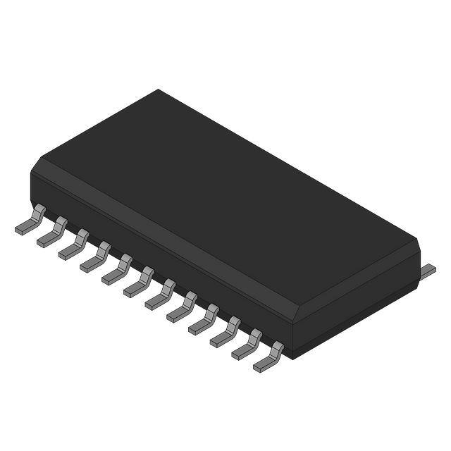
DW PACKAGE
(TOP VIEW)
DRAIN5
DRAIN4
SCLK
SDI
GND
GND
GND
GND
SDO
CS
DRAIN3
DRAIN2
description
The TPIC2603 is a monolithic low-side driver which
provides serial interface and diagnostics to control
six on-board power DMOS switches. Each channel
has independent OFF-state open-load sense,
ON-state shorted-load/short-to-battery protection,
over-battery-voltage-lockout
protection,
and
over-temperature sense with fault status reported
through the serial interface. The device also
provides inductive voltage transient protection for
each drain output. The TPIC2603 drives inductive
and resistive loads such as relays, valves, and
lamps.
1
24
2
23
3
22
4
21
5
20
6
19
7
18
8
17
9
16
10
15
11
14
12
13
Vbat
DRAIN0
NC
NC
GND
GND
GND
GND
NC
NC
DRAIN1
VCC
NC − No internal connection
Serial data input (SDI) is transferred through the serial register when CS is low on low-to-high transitions of the
serial clock (SCLK). Each string of data must consist of 8 or 16 bits of data. A logic high input data bit turns the
respective output channel ON and a logic low data bit turns it OFF. CS must be transited high after all of the serial
data has been clocked into the device. A low-to-high transition of CS transfers the last six bits of serial data to
the output buffer, places the serial data out (SDO) terminal in a high-impedance state, and re-enables the fault
register. Fault data for the device is sent out the SDO terminal. The first bit of the shift register is exclusively
ORed with the fault registers. When a fault exists, the SDI data is inverted as it is transferred out of SDO. Fault
data consists of fault flags for over-temperature (bit 6) and shorted/open-load (bits 0-5) for each of the six output
channels. Fault register bits are set or cleared asynchronously, when CS is high to reflect the current state of
the hardware. The fault must be present when CS is transited from high to low to be captured and reported in
the serial fault data. New faults cannot be captured in the serial register when CS is low.
Please be aware that an important notice concerning availability, standard warranty, and use in critical applications of
Texas Instruments semiconductor products and disclaimers thereto appears at the end of this data sheet.
Copyright 1996, Texas Instruments Incorporated
���������� ���� ����������� �� !"��#�� �� �� $"%&�!����� '��#(
���'"!�� !������ �� �$#!���!������ $#� �)# �#��� �� �#*�� �����"�#���
����'��' +������,( ���'"!���� $��!#����- '�#� ��� �#!#�����&, ��!&"'#
�#����- �� �&& $����#�#��(
•
POST OFFICE BOX 655303 DALLAS, TEXAS 75265
POST OFFICE BOX 1443 HOUSTON, TEXAS 77251−1443
•
1
���������
� �
���
� �
���� ���
����
��� ���
����
�
SLIS056A − FEBRUARY 1995 − REVISED MARCH 1996
description (continued)
When an over-current or shorted-load fault occurs, the channel transits into a low duty cycle
pulse-width-modulated (PWM) signal as long as the fault is present. More detail on fault detection operation is
presented in the device operation section of this data sheet.
The TPIC2603 provides pulldown resistors on all active-high inputs except SCLK. A pullup resistor is
used on CS.
The TPIC2603 is characterized for operation over the operating case temperature of − 40°C to 125°C.
functional block diagram
SCLK
Serial Input Control
6-Bit Shift Register
CS
SDI
Output Drivers
Vbat
VCC
DRAIN0
DRAIN1
DRAIN2
DRAIN3
DRAIN4
DRAIN5
Fault Sense and Protection
(STB, Current-Limit, Open-Load,
Over-Temperature, Over-Voltage)
Fault Register
SDO
2
•
POST OFFICE BOX 655303 DALLAS, TEXAS 75265
POST OFFICE BOX 1443 HOUSTON, TEXAS 77251−1443
•
���������
� �
���
� �
���� ���
����
��� ���
����
�
SLIS056A − FEBRUARY 1995 − REVISED MARCH 1996
Terminal Functions
TERMINAL
I/O
DESCRIPTION
8 (10)
I
Chip select. The CS is an active-low input used to select the serial interface of the device. The device accepts
serial input data and transmits fault data when CS is held low. An internal pullup resistor is provided on the CS
input.
19 (23)
12 (14)
10 (12)
9 (11)
2 (2)
1 (1)
O
FET drain outputs. The DRAIN terminals are low-side switches for inductive and resistive loads. Each output
provides an internal drain-gate clamp to snub inductive transients.
5, 6, 15,
16 (5, 6, 7,
8, 17, 18,
19, 20)
O
Ground. These terminals provide ground return paths for the device.
SCLK
3 (3)
I
Serial clock. The SCLK clocks the shift register. Serial data is transferred into the SDI port and serial fault data
is transferred out of the SDO port of the device on the rising edges of SCLK.
SDI
4 (4)
I
Serial data input. The device receives serial data from the control device using the SDI. Serial input data can
be configured in 8-bit or 16-bit data words. Refer to Figures 2 and 4 for input protocol. An internal pulldown
resistor is provided on the SDI input.
SDO
7 (9)
O
Serial data output. This 3-state output transfers fault data to the control device after the device has been
selected by the CS terminal.
Vbat
VCC
20 (24)
I
Battery voltage. The Vbat terminal monitors the battery voltage to detect over-voltage conditions.
11 (13)
I
Supply voltage. The VCC terminal receives a 5-V supply for internal logic.
NAME
CS
DRAIN0
DRAIN1
DRAIN2
DRAIN3
DRAIN4
DRAIN5
GND
NO.†
† Terminal numbers listed in parenthesis are for the 24-pin DW package.
absolute maximum ratings over the recommended operating case temperature range (unless
otherwise noted)‡
Logic supply voltage range, VCC (see Note 1) . . . . . . . . . . . . . . . . . . . . . . . . . . . . . . . . . . . . . . . . . −0.3 V to 7 V
Battery supply voltage range, Vbat . . . . . . . . . . . . . . . . . . . . . . . . . . . . . . . . . . . . . . . . . . . . . . . . . . −1.5 V to 60 V
Logic input voltage range, VI . . . . . . . . . . . . . . . . . . . . . . . . . . . . . . . . . . . . . . . . . . . . . . . . . . . . . . . . −0.3 V to 7 V
Power DMOS drain-to-source voltage, VDS (see Note 2) . . . . . . . . . . . . . . . . . . . . . . . . . . . . . . . . . . . . . . . 68 V
Continuous drain current, each output, all outputs on, ID, TC = 25°C . . . . . . . . . . . . . . . . . . . . . . . . . . . 350 mA
Pulsed drain current, single output, IDM, TC = 25°C (see Note 3) . . . . . . . . . . . . . . . . . . . . . . . . . . . . . . . 2.25 A
Single-pusle avalanche energy, EAS (see Figure 11) . . . . . . . . . . . . . . . . . . . . . . . . . . . . . . . . . . . . . . . . . 100 mJ
Continuous total power dissipation . . . . . . . . . . . . . . . . . . . . . . . . . . . . . . . . . . . . . See Dissipation Rating Table
Avalanche current, IAS (see Note 4) . . . . . . . . . . . . . . . . . . . . . . . . . . . . . . . . . . . . . . . . . . . . . . . . . . . . . . . . . . 1 A
Operating virtual junction temperature range, TJ . . . . . . . . . . . . . . . . . . . . . . . . . . . . . . . . . . . . −40°C to 150°C
Storage temperature range, Tstg . . . . . . . . . . . . . . . . . . . . . . . . . . . . . . . . . . . . . . . . . . . . . . . . . . −55°C to 150°C
Lead temperature 1,6 mm (1/16 inch) from case for 10 seconds . . . . . . . . . . . . . . . . . . . . . . . . . . . . . . . 260°C
‡ Stresses beyond those listed under “absolute maximum ratings” may cause permanent damage to the device. These are stress ratings only, and
functional operation of the device at these or any other conditions beyond those indicated under “recommended operating conditions” is not
implied. Exposure to absolute-maximum-rated conditions for extended periods may affect device reliability.
NOTES: 1. All voltage values are with respect to GND.
2. Each power DMOS source is internally connected to GND.
3. Pulse duration ≤ 100 µs and duty cycle ≤ 2%.
4. DRAIN supply voltage = 13 V, starting junction temperature (TJS) = 25°C, L = 150 mH, IAS = 1 A (see Figure 11).
•
POST OFFICE BOX 655303 DALLAS, TEXAS 75265
POST OFFICE BOX 1443 HOUSTON, TEXAS 77251−1443
•
3
���������
� �
���
� �
���� ���
����
��� ���
����
�
SLIS056A − FEBRUARY 1995 − REVISED MARCH 1996
DISSIPATION RATING TABLE
PACKAGE
TC ≤ 25°C
POWER RATING
DERATING FACTOR
ABOVE TC = 25°C
TC = 125°C
POWER RATING
DW
1750 mW
14 mW/°C
350 mW
NE
2500 mW
20 mW/°C
500 mW
recommended operating conditions
MIN
NOM
MAX
4.5
5
5.5
V
Battery supply voltage, Vbat
5.5
12
High-level input voltage, VIH
0.7 VCC
Logic supply voltage, VCC
Low-level input voltage, VIL
Operating case temperature, TC
UNIT
25
V
V
0
VCC
0.3 VCC
−40
125
°C
MAX
UNIT
V
electrical characteristics, TC = −40°C to 125°C (unless otherwise noted)
PARAMETER
Vbat
TEST CONDITIONS
Battery supply voltage
Normal operation
Ibat
Battery supply current
VCC = 5 V
VCC = 0
VCC
ICC
Logic supply voltage
MIN
4.5
Logic supply current
All outputs off,
Vbat = 5.5 V
V(turn-on)
VCC turn-on voltage
(logic operational)
Vbat = 5.5 V,
Check output functionality
V(ov)
Over-battery voltage
shutdown
Gate disabled
Vhys(ov)
Over-battery voltage reset
hysteresis
rDS(on)
Drain-to-source on-state
resistance
TYP
5.5
Vbat = 13 V
Vbat = 5.5 V
IO = 0.35 A,
Vbat = 13 V
Vbat = 5.5 V
IO = 0.35 A,
25
V
5
mA
50
µA
5.5
V
5
mA
4.5
V
30
38
V
0.4
2
V
TC = 25°C
TC = 125°C
1
1.7
2.3
1.2
1.7
2.7
3.8
2
5
Ω
IL
IL(sense)
On-state current limit
0.8
1.5
3
A
IIH
IIL
Input pullup current
GND < VI < 0.7 VCC,
CS input only
−5
−10
−50
µA
Input pulldown current
0.3 VCC < VI < VCC,
All other inputs
2.5
10
25
µA
ID(off)
IO(sleep)
Off-state drain current
20
40
80
µA
Sleep-state output current
Vload = Vbat = 14.5 V
Vbat < 0.5 V,
50
µA
VOH
High-level serial output
voltage
IO = 1 mA
VOL
Low-level serial output
voltage
IO = 1 mA
IOZ
High impedance state
output current
VCC = 5.5 V to 0 V,
SDO output
V(BR)DSX
Drain-to-source breakdown
voltage
dc < 1%,
tw = 100 µs,
Over-current sense
Tj(sense)
Tj(hys)
Thermal flag
V(open)
Open-load detection voltage
4
0.8
0.7
VCC < 0.5 V, Load = 14 V
0.8 VCC
IO = 20 mA
Thermal flag hysteresis
•
•
V
0.2
0.4
V
−10
1
10
µA
52
58
68
V
150
170
185
°C
5
10
15
°C
0.7 VCC
V
0.3 VCC
POST OFFICE BOX 655303 DALLAS, TEXAS 75265
POST OFFICE BOX 1443 HOUSTON, TEXAS 77251−1443
A
���������
� �
���
� �
���� ���
����
��� ���
����
�
SLIS056A − FEBRUARY 1995 − REVISED MARCH 1996
switching characteristics, VCC = 5 V, TC = 25°C
TYP
MAX
UNIT
tw
twH(SCLK)
Clock cycle period pulse duration, SCLK
PARAMETER
See Figure 1
TEST CONDITIONS
MIN
250
555
ns
Pulse duration, SCLK high
See Figure 1
100
248
ns
twL(SCLK)
Pulse duration, SCLK low
See Figure 1
100
248
ns
tpd1
Propagation delay from falling edge of CS to SDO valid
CS = 0.8 V to SDO low
impedance (see Figure 1)
150
300
ns
tpd2
tpd3
Propagation delay from rising edge of CS to SDO 3-state
CS = 2 V to SDO 3-state
150
200
ns
Propagation delay from SCLK to SDO valid
CS < 0.8 V
80
172
ns
tr(SDO)
tf(SDO)
Rise time of SDO
Cload = 200 pF
30
50
ns
Fall time of SDO
Cload = 200 pF
30
50
ns
t(stb)
td(on)
Short-to-battery/shorted-load/open-load deglitch time
See Figures 5 and 6
µs
td(off)
tr(drain)
Turn-off delay time, rising edge of CS to drain
tf(drain)
f(SCLK)
tcyc(ref)
tw(sense)
Short-to-battery sense cycle time
See Figure 5
1.6
4
6.4
ms
Short-to-battery sense pulse duration
See Figure 5
25
70
100
µs
tsu1
tsu(SDI)
Setup to/from the fall edge of CS to the rising edge of SCLK
See Figure 1
150
200
ns
Setup time, SDI to SCLK
See Figure 1
25
55
ns
th(SDI)
Hold time, SDI after SCLK
See Figure 1
10
55
ns
MIN
MAX
25
70
100
0.4
5
10
0.4
5
15
0.4
5
10
Fall time of drain terminal
0.4
5
10
Serial clock frequency
1.8
4
Turn-on delay time, rising edge of CS to drain
Vbat = 14 V,
Rload = 30 Ω
Rise time of drain terminal
µss
MHz
thermal resistance
PARAMETER
TEST CONDITIONS
UNIT
RθJA
Junction-to-ambient thermal resistance
All outputs with equal power
50
°C
RθJC
Junction-to-case thermal resistance
All outputs with equal power
10
°C
•
POST OFFICE BOX 655303 DALLAS, TEXAS 75265
POST OFFICE BOX 1443 HOUSTON, TEXAS 77251−1443
•
5
���������
� �
���
� �
���� ���
����
��� ���
����
�
SLIS056A − FEBRUARY 1995 − REVISED MARCH 1996
PRINCIPLES OF OPERATION
tw
twH(SCLK)
tsu1
twL(SCLK)
1
SCLK
2
3
X
tsu(SDI)
CS
th(SDI)
MSB
SDI
MSB
3-STATE
SDO
LSB
LSB
tpd3
tpd1
3-STATE
tpd2
Figure 1. Switching Characteristics
serial interface
Control information is transferred into the TPIC2603 through the serial interface. The serial interface consists
of a serial clock (SCLK), chip select (CS), serial data input (SDI), and serial data output (SDO). Serial data is
shifted, most significant bit (MSB) first, into the SDI shift register on the rising edge of the first SCLK after CS
has transited from high to low. The controller must shift either eight bits or sixteen bits of data into the device
with the last six bits of input data containing control information for the output drivers. Data bits preceeding the
output control information should be set to 0. A low-to-high transition on CS latches the contents of the last six
bits of the serial shift register into the output buffer. A low input to SDI turns the corresponding parallel output
OFF and a high input will turn the output ON (see Figure 2).
1
2
3
4
5
SCLK
CS
SDI
NEW DATA
0
DRAIN5
DRAIN4
DRAIN3
DRAIN2
DRAIN1
DRAIN0
OFF
ON
ON
OFF
OFF
ON
Figure 2. Serial Input Control
6
•
POST OFFICE BOX 655303 DALLAS, TEXAS 75265
POST OFFICE BOX 1443 HOUSTON, TEXAS 77251−1443
•
6
7
8
���������
� �
���
� �
���� ���
����
��� ���
����
�
SLIS056A − FEBRUARY 1995 − REVISED MARCH 1996
PRINCIPLES OF OPERATION
serial interface (continued)
Fault isolation data for each channel and global over-temperature status is transferred to the control device
using the serial interface. Fault status for the TPIC2603 is captured as CS transits low. The fault interface
monitors the SDI terminal and exclusively ORs the respective input control bit with the corresponding fault
information bit stored in the fault register. Each exclusive ORed fault bit is transferred out the SDO terminal on
the rising edge of the SCLK. Serial data can be transferred in 8-bit or 16-bit words as illustrated in Figure 4, with
fault data appearing in the first 8-bits of serial output data. The CS must be transited high after the serial transfer
has completely latched the new control data into the output control buffer and re-enable fault reporting on the
device (see Figures 3 and 4).
1
2
3
4
5
6
7
8
OT
FLT5
FLT4
FLT3
FLT2
FLT1
FLT0
Bit6
Bit5
Bit4
Bit3
Bit2
Bit1
Bit0
SCLK
CS
SDO
3-STATE
N/A
Bit7
3-STATE
NA = Unused
OT = Over-temperature fault bit
FLT5 = Shorted or open-load fault on channel 5
FLT4 = Shorted or open-load fault on channel 4
FLT3 = Shorted or open-load fault on channel 3
FLT2 = Shorted or open-load fault on channel 2
FLT1 = Shorted or open-load fault on channel 1
FLT0 = Shorted or open-load fault on channel 0
NOTE A: MSB is the first bit transferred.
Figure 3. Serial Output Control
•
POST OFFICE BOX 655303 DALLAS, TEXAS 75265
POST OFFICE BOX 1443 HOUSTON, TEXAS 77251−1443
•
7
���������
� �
���
� �
���� ���
����
��� ���
����
�
SLIS056A − FEBRUARY 1995 − REVISED MARCH 1996
PRINCIPLES OF OPERATION
serial interface (continued)
Serial I/O Protocol (8-Bit Configuration)
MSB
7
6
5
4
3
2
1
0
N/A
Over
Temp
5
4
3
2
1
0
LSB
Unused
Output control data for Drain (0:5). Fault
data for Drain (0:5) is exclusive ORed and
transmitted in the respective bit locations.
Global over-temperature flag
Serial I/O Protocol (16-Bit Configuration)
MSB 15
14
N/A
Over
Temp
Unused
13
12
11
10
9
8
7
6
5
4
3
2
1
0 LSB
5
4
3
2
1
0
N/A
N/A
5
4
3
2
1
0
Output control data for Drain (0:5). Fault
data for Drain (0:5) is exclusive ORed and
transmitted in the respective bit locations.
Output control data for Drain (0:5)
Global over-temperature flag
NOTE A: MSB is the first bit transferred.
Figure 4. Serial Data Fault Protocol
8
•
POST OFFICE BOX 655303 DALLAS, TEXAS 75265
POST OFFICE BOX 1443 HOUSTON, TEXAS 77251−1443
•
���������
� �
���
� �
���� ���
����
��� ���
����
�
SLIS056A − FEBRUARY 1995 − REVISED MARCH 1996
PRINCIPLES OF OPERATION
fault sense/protection circuitry
over-current/short-to-battery sensing and protection
The internal fault protection circuitry of the TPIC2603 monitors the drain current for each channel. Each channel
offers two levels of protection from over-current conditions. The first level is a current-limit protection which
through the internal FET prevents the switching current from exceeding the on-state current limit. The second
level of protection transits the output to a low duty cycle PWM mode when the current exceeds the over-current
sense threshold. The PWM mode protection is enabled approximately 70 µs after the output has been turned
on. The output remains in the PWM mode until the shorted-load condition has been corrected and then
automatically returns to normal operation. Figure 5 illustrates device operation under an over-current or
shorted-load condition.
NORMAL
Control
Register
Glitches
DRAIN
Fault
Register
t(stb)
SHORTED-LOAD
DRAIN
Control
Register
tw(sense)
tcyc(ref)
Glitches
DRAIN
Fault
Register
t(stb)
Figure 5. Shorted-Load Condition
•
POST OFFICE BOX 655303 DALLAS, TEXAS 75265
POST OFFICE BOX 1443 HOUSTON, TEXAS 77251−1443
•
9
���������
� �
���
� �
���� ���
����
��� ���
����
�
SLIS056A − FEBRUARY 1995 − REVISED MARCH 1996
PRINCIPLES OF OPERATION
open-load/short-to-ground sensing
The TPIC2603 checks for open-load and short-to-ground conditions when the output is turned OFF. When the
output turns OFF, a 40-µA current source switches onto the drain. Under normal conditions, the load provides
adequate current to overcome the current source and the drain voltage remains above the open-load detection
threshold. When the output is open, then the current source pulls the drain low and an open-load condition is
flagged. The open-load test is enabled approximately 70 µs after the output turns OFF to allow the drain to
stabilize. Figure 6 illustrates device operation under open-load conditions.
NORMAL
OPEN-LOAD
Control
Register
Control
Register
Glitches
DRAIN
DRAIN
Fault
Register
Fault
Register
t(stb)
t(stb)
Figure 6. Open-Load Condition
over-voltage sensing and protection
The TPIC2603 monitors the Vbat input terminal to protect the device and load from over-battery voltage
conditions. The device disables all of the drain outputs when Vbat goes above 35 V. An over-battery voltage
hysteresis is provided to prevent the outputs from transiting ON and OFF erratically near the over-voltage
threshold. The device automatically returns to normal operation after the over-voltage condition has been
corrected. Figure 7 illustrates device operation under an over-battery voltage condition.
Vbat (Typ)
35 V
34 V
All Drains
Fault Bit
Figure 7. Over-Battery Voltage Condition
10
•
POST OFFICE BOX 655303 DALLAS, TEXAS 75265
POST OFFICE BOX 1443 HOUSTON, TEXAS 77251−1443
•
���������
� �
���
� �
���� ���
����
��� ���
����
�
SLIS056A − FEBRUARY 1995 − REVISED MARCH 1996
PRINCIPLES OF OPERATION
over-temperature sensing
The TPIC2603 monitors the junction temperature of the die to detect over-temperature conditions which may
damage the device. When the junction temperature goes above approximately 170°C, the fault logic sets the
global over-temperature fault bit. An over-temperature fault is reported using the serial interface on bit 6 (for 8-bit
configuration) or bit 14 (for 16-bit configuration). The global over-temperature fault output in the serial data is
exclusively ORed with the second bit (bit 6 for 8-bit configuration or bit 14 for 16-bit configuration) of data input
to the SDI terminal. Bit 6 or bit 14 of the input data should be set low. Over-temperature faults are for
informational purposes only and do not affect the state of the drains. Figure 8 illustrates device operation under
over-temperature conditions.
Junction Temperature
170°C
160°C
Drains (Not Disabled)
Fault Bit
Figure 8. Over-Temperature Sense
PARAMETER MEASUREMENT INFORMATION
OUTPUT CURRENT
vs
TIME FOR INCREASING LOAD RESISTANCE
REGION 1 CURRENT WAVEFORM
3
TC = 25°C
I O − Output Current − A
I O − Output Current − A
IL
2
1
0
t1
t2
t1
t2
t1
t1 ≈ 55 µs
t2 ≈ 3.5 ms
0
Region 1
Region 2
Region 3
t -Time
t - Time
First output current pulses after turn-on in chopping mode with
resistive load.
NOTES: A. Region 1 − Analog current limit holds the maximum current while the device runs in chop mode.
B. Region 2 − Analog current limit is removed but device continues in chop mode.
C. Region 3 − Current is below chop mode sense; therefore, it is in normal operation. Variable load is resistance over time.
Figure 9. Chopping-Mode Characteristics
•
POST OFFICE BOX 655303 DALLAS, TEXAS 75265
POST OFFICE BOX 1443 HOUSTON, TEXAS 77251−1443
•
11
���������
� �
���
� �
���� ���
����
��� ���
����
�
SLIS056A − FEBRUARY 1995 − REVISED MARCH 1996
PARAMETER MEASUREMENT INFORMATION
OVER-CURRENT SENSE, IL(sense)
vs
CASE TEMPERATURE
I L(sense) − Over Current Sense − A
3
IL
2
IL(sense)
1
0
− 50
0
100
50
150
TC − Case Temperature − °C
Figure 10
5V
tw
13 V
tav†
5V
11
VCC
3
Word
Generator
(see Note A)
4
8
Input
20
Vbat
See Note B
1Ω
ID
SCLK
DUT
ID
150 mH
SDI
CS
0V
IAS = 1 A
DRAIN
VDS
VDS
V(BR)DSX = 52 V MIN
GND
5, 6, 15, 16
Pinout for NE Package Shown
VOLTAGE AND CURRENT WAVEFORMS
SINGLE-PULSE AVALANCHE ENERGY TEST CIRCUIT
† Non-JEDEC symbol for avalanche time.
NOTES: A. The word generator has the following characteristics: tr ≤ 10 ns, tf ≤ 10 ns, ZO = 50 Ω.
B. Input pulse duration, tw, is increased until peak current IAS = 1 A.
Energy test level is defined as EAS = (IAS × V(BR)DSX × tav)/2 = 100 mJ.
Figure 11. Single-Pulse Avalanche Energy Test Circuit and Waveforms
12
•
POST OFFICE BOX 655303 DALLAS, TEXAS 75265
POST OFFICE BOX 1443 HOUSTON, TEXAS 77251−1443
•
���������
� �
���
� �
���� ���
����
��� ���
����
�
SLIS056A − FEBRUARY 1995 − REVISED MARCH 1996
TYPICAL CHARACTERISTICS
IDM − Maximum Peak Drain Current of Each Output − A
MAXIMUM CONTINUOUS
DRAIN CURRENT OF EACH OUTPUT
vs
NUMBER OF OUTPUTS CONDUCTING
SIMULTANEOUSLY
ID − Maximum Continuous Drain Current
of Each Output − A
1.6
VCC = 5 V
Vbat = 13 V
1.4
1.2
TC = 25°C
1
0.8
TC = 100°C
0.6
0.4
TC = 125°C
0.2
0
1
2
3
4
5
6
N − Number of Outputs Conducting Simultaneously
MAXIMUM PEAK DRAIN CURRENT
OF EACH OUTPUT
vs
NUMBER OF OUTPUTS CONDUCTING
SIMULTANEOUSLY
1.2
VCC = 5 V
Vbat = 13 V
TC = 25°C
1.1
1
d = 80%
0.9
d = 85%
d = 90%
0.8
0.7
0.6
1
2
3
4
5
6
N − Number of Outputs Conducting Simultaneously
Figure 13
r DS(on) − Static Drain-Source On-State Resistance − Ω
STATIC DRAIN-SOURCE ON-STATE RESISTANCE
vs
DRAIN CURRENT
1.25
VCC = 5 V
Vbat = 13 V
See Note A
TC = 125°C
1
IL
0.75
TC = 25°C
IL(sense)
0.5
TC = − 40°C
0.25
0
0
1
2
3
r DS(on) − Static Drain-Source On-State Resistance − Ω
Figure 12
STATIC DRAIN-SOURCE ON-STATE RESISTANCE
vs
LOGIC SUPPLY VOLTAGE
1.5
VCC = 5 V
ID = 350 mA
See Note A
1.25
TC = 125°C
1
0.75
TC = 25°C
0.5
TC = − 40°C
0.25
0
0
10
5
15
20
25
30
VCC − Logic Supply Voltage − V
ID − Drain Current − A
NOTE A: Technique should limit TJ − TC to 10°C maximum.
NOTE A: Technique should limit TJ − TC to 10°C maximum.
Figure 14
Figure 15
•
POST OFFICE BOX 655303 DALLAS, TEXAS 75265
POST OFFICE BOX 1443 HOUSTON, TEXAS 77251−1443
•
13
���������
� �
���
� �
���� ���
����
��� ���
����
�
SLIS056A − FEBRUARY 1995 − REVISED MARCH 1996
THERMAL INFORMATION
NE PACKAGE
TRANSIENT THERMAL IMPEDANCE
vs
ON TIME
The single-pulse curve represents measured data. The
curves for various pulse durations are based on the
following equation:
Z θJA− Transient Thermal Impedance − ° C /W
100
Zq
d = 50%
Where:
JA
+
Ť tt Ť
Rq
JA
)
Ť
1
–
tw
tc
Ť
Z q ǒt w ) t c Ǔ
) Z qǒt wǓ–Z qǒt cǓ
d = 20%
10
Z qǒt wǓ = the single-pulse thermal impedance
for t = tw seconds
d = 10%
Z qǒt cǓ = the single-pulse thermal impedance
for t = tc seconds
d = 5%
1
Z qǒt w ) t cǓ = the single-pulse thermal impedance
for t = tw + tc seconds
d = 2%
d = tw/tc
tc
Single Pulse
tw
0.1
0.001
0.01
0.1
1
10
100
1000
Figure 16
•
POST OFFICE BOX 655303 DALLAS, TEXAS 75265
POST OFFICE BOX 1443 HOUSTON, TEXAS 77251−1443
•
ID
0
t − On Time − s
14
w
c
�PACKAGE OPTION ADDENDUM
www.ti.com
10-Dec-2020
PACKAGING INFORMATION
Orderable Device
Status
(1)
Package Type Package Pins Package
Drawing
Qty
Eco Plan
(2)
Lead finish/
Ball material
MSL Peak Temp
Op Temp (°C)
Device Marking
(3)
(4/5)
(6)
TPIC2603DW
ACTIVE
SOIC
DW
24
25
RoHS & Green
NIPDAU
Level-1-260C-UNLIM
TPIC2603DWG4
ACTIVE
SOIC
DW
24
25
RoHS & Green
NIPDAU
Level-1-260C-UNLIM
TPIC2603DWR
ACTIVE
SOIC
DW
24
2000
RoHS & Green
NIPDAU
Level-1-260C-UNLIM
TPIC2603DWRG4
ACTIVE
SOIC
DW
24
2000
RoHS & Green
NIPDAU
Level-1-260C-UNLIM
-40 to 125
TPIC2603
TPIC2603
-40 to 125
TPIC2603
TPIC2603
(1)
The marketing status values are defined as follows:
ACTIVE: Product device recommended for new designs.
LIFEBUY: TI has announced that the device will be discontinued, and a lifetime-buy period is in effect.
NRND: Not recommended for new designs. Device is in production to support existing customers, but TI does not recommend using this part in a new design.
PREVIEW: Device has been announced but is not in production. Samples may or may not be available.
OBSOLETE: TI has discontinued the production of the device.
(2)
RoHS: TI defines "RoHS" to mean semiconductor products that are compliant with the current EU RoHS requirements for all 10 RoHS substances, including the requirement that RoHS substance
do not exceed 0.1% by weight in homogeneous materials. Where designed to be soldered at high temperatures, "RoHS" products are suitable for use in specified lead-free processes. TI may
reference these types of products as "Pb-Free".
RoHS Exempt: TI defines "RoHS Exempt" to mean products that contain lead but are compliant with EU RoHS pursuant to a specific EU RoHS exemption.
Green: TI defines "Green" to mean the content of Chlorine (Cl) and Bromine (Br) based flame retardants meet JS709B low halogen requirements of