���������
�
��
��� ����� ����� ��������
SLIS005B − APRIL 1993 − REVISED MAY 2005
D
D
D
D
D
D
D
Low rDS(on) . . . 1 Ω Typ
Output Short-Circuit Protection
Avalanche Energy . . . 75 mJ
Eight 350-mA DMOS Outputs
50-V Switching Capability
Devices Are Cascadable
Low Power Consumption
description
The TPIC6A595 is a monolithic, high-voltage,
high-current power logic 8-bit shift register
designed for use in systems that require relatively
high load power. The device contains a built-in
voltage clamp on the outputs for inductive
transient protection. Power driver applications
include relays, solenoids, and other medium-current or high-voltage loads. Each open-drain
DMOS transistor features an independent
chopping current-limiting circuit to prevent
damage in the case of a short circuit.
NE PACKAGE
(TOP VIEW)
DRAIN2
DRAIN3
SRCLR
G
PGND
PGND
RCK
SRCK
DRAIN4
DRAIN5
1
20
2
19
3
18
4
17
5
16
6
15
7
14
8
13
9
12
10
11
DRAIN1
DRAN0
SER IN
VCC
PGND
PGND
LGND
SER OUT
DRAIN7
DRAIN6
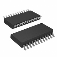
DW PACKAGE
(TOP VIEW)
DRAIN2
DRAIN3
SRCLR
G
PGND
PGND
PGND
PGND
RCK
SRCK
DRAIN4
DRAIN5
1
24
2
23
3
22
4
21
5
20
6
19
DRAIN1
DRAIN0
SER IN
VCC
PGND
PGND
PGND
PGND
LGND
SER OUT
DRAIN7
DRAIN6
This device contains an 8-bit serial-in, parallel-out
18
7
shift register that feeds an 8-bit, D-type storage
17
8
register. Data transfers through both the shift and
16
9
storage registers on the rising edge of the shift15
10
register clock (SRCK) and the register clock
14
11
(RCK), respectively. The storage register
13
12
transfers data to the output buffer when shiftregister clear (SRCLR) is high. When SRCLR is
low, the input shift register is cleared. When output
enable (G) is held high, all data in the output buffers is held low and all drain outputs are off. When G is held
low, data from the storage register is transparent to the output buffers. The serial output (SER OUT) allows for
cascading of the data from the shift register to additional devices.
Outputs are low-side, open-drain DMOS transistors with output ratings of 50 V and a 350-mA continuous sink
current capability. When data in the output buffers is low, the DMOS-transistor outputs are off. When data is high,
the DMOS-transistor outputs have sink current capability.
Separate power ground (PGND) and logic ground (LGND) terminals are provided to facilitate maximum system
flexibility. All PGND terminals are internally connected, and each PGND terminal must be externally connected
to the power system ground in order to minimize parasitic impedance. A single-point connection between LGND
and PGND must be made externally in a manner that reduces crosstalk between the logic and load circuits.
The TPIC6A595 is offered in a thermally-enhanced dual-in-line (NE) package and a wide-body surface-mount
(DW) package. The TPIC6A595 is characterized for operation over the operating case temperature range of
−40°C to 125°C.
Copyright 1995 − 2005, Texas Instruments Incorporated
�� ����� � ���� ����������� �! "#��$�� �! �� %#&'�"����� (��$)
���(#"�! "������ �� !%$"���"�����! %$� �*$ �$��! �� �$+�! ��!��#�$��!
!���(��( ,������-) ���(#"���� %��"$!!��. (�$! ��� �$"$!!���'- ��"'#($
�$!���. �� �'' %����$�$�!)
POST OFFICE BOX 655303
• DALLAS, TEXAS 75265
1
����������
�
��
��� ����� ����� ��������
SLIS005B − APRIL 1993 − REVISED MAY 2005
logic symbol†
G
EN3
RCK
C2
SRCLR
SRCK
SER IN
R
SRG8
C1
1D
2
3
DRAIN0
DRAIN1
DRAIN2
DRAIN3
DRAIN4
DRAIN5
DRAIN6
2
3
DRAIN7
SER OUT
† This symbol is in accordance with ANSI/IEEE Std 91-1984 and IEC Publication 617-12.
2
POST OFFICE BOX 655303
• DALLAS, TEXAS 75265
����������
�
��
��� ����� ����� ��������
SLIS005B − APRIL 1993 − REVISED MAY 2005
logic diagram (positive logic)
G
DRAIN0
RCK
D
SRCK
C1
SRCLR
CLR
D
C1
D
C2
DRAIN1
D
C2
DRAIN2
CLR
D
C1
D
C2
CLR
D
C1
Current Limit and Charge Pump
SER IN
D
C2
CLR
D
C1
D
C2
CLR
DRAIN3
DRAIN4
DRAIN5
D
C1
D
C2
CLR
D
C1
DRAIN6
D
C2
CLR
D
C1
D
C2
DRAIN7
CLR
SER OUT
POST OFFICE BOX 655303
• DALLAS, TEXAS 75265
PGND
3
����������
�
��
��� ����� ����� ��������
SLIS005B − APRIL 1993 − REVISED MAY 2005
schematic of inputs and outputs
TYPICAL OF SERIAL OUT
EQUIVALENT OF EACH INPUT
VCC
TYPICAL OF ALL DRAIN OUTPUTS
DRAIN
VCC
Input
SER OUT
25 V
12 V
RSENSE
LGND
LGND
PGND
LGND
absolute maximum ratings over recommended operating case temperature range (unless
otherwise noted)†
Logic supply voltage, VCC (see Note 1) . . . . . . . . . . . . . . . . . . . . . . . . . . . . . . . . . . . . . . . . . . . . . . . . . . . . . . . 7 V
Logic input voltage range, VI . . . . . . . . . . . . . . . . . . . . . . . . . . . . . . . . . . . . . . . . . . . . . . . . . . . . . . . . −0.3 V to 7 V
Power DMOS drain-to-source voltage, VDS (see Note 2) . . . . . . . . . . . . . . . . . . . . . . . . . . . . . . . . . . . . . . . . 50 V
Continuous source-drain diode anode current . . . . . . . . . . . . . . . . . . . . . . . . . . . . . . . . . . . . . . . . . . . . . . . . . . 1 A
Pulsed source-drain diode anode current (see Note 3) . . . . . . . . . . . . . . . . . . . . . . . . . . . . . . . . . . . . . . . . . . . 2 A
Pulsed drain current, each output, all outputs on, IDn, TA = 25°C (see Note 3) . . . . . . . . . . . . . . . . . . . . . 1.1 A
Continuous drain current, each output, all outputs on, IDn, TA = 25°C . . . . . . . . . . . . . . . . . . . . . . . . . . 350 mA
Peak drain current, single output, TA = 25°C (see Note 3) . . . . . . . . . . . . . . . . . . . . . . . . . . . . . . . . . . . . . . 1.1 A
Single-pulse avalanche energy, EAS (see Figure 6) . . . . . . . . . . . . . . . . . . . . . . . . . . . . . . . . . . . . . . . . . . . 75 mJ
Avalanche current, IAS (see Note 4) . . . . . . . . . . . . . . . . . . . . . . . . . . . . . . . . . . . . . . . . . . . . . . . . . . . . . . 600 mA
Continuous total dissipation . . . . . . . . . . . . . . . . . . . . . . . . . . . . . . . . . . . . . . . . . . . See Dissipation Rating Table
Operating case temperature range, TC . . . . . . . . . . . . . . . . . . . . . . . . . . . . . . . . . . . . . . . . . . . . . −40°C to 125°C
Operating virtual junction temperature range, TJ . . . . . . . . . . . . . . . . . . . . . . . . . . . . . . . . . . . . . −40°C to 150°C
Storage temperature range, Tstg . . . . . . . . . . . . . . . . . . . . . . . . . . . . . . . . . . . . . . . . . . . . . . . . . . . −65°C to 150°C
Lead temperature 1,6 mm (1/16 inch) from case for 10 seconds . . . . . . . . . . . . . . . . . . . . . . . . . . . . . . . 260°C
† Stresses beyond those listed under “absolute maximum ratings” may cause permanent damage to the device. These are stress ratings only, and
functional operation of the device at these or any other conditions beyond those indicated under “recommended operating conditions” is not
implied. Exposure to absolute-maximum-rated conditions for extended periods may affect device reliability.
NOTES: 1. All voltage values are with respect to LGND and PGND.
2. Each power DMOS source is internally connected to PGND.
3. Pulse duration ≤ 100 µs and duty cycle ≤ 2 %.
4. DRAIN supply voltage = 15 V, starting junction temperature (TJS) = 25°C, L = 210 mH, IAS = 600 mA (see Figure 6).
DISSIPATION RATING TABLE
4
PACKAGE
TC ≤ 25°C
POWER RATING
DERATING FACTOR
ABOVE TC = 25°C
TC = 125°C
POWER RATING
DW
1750 mW
14 mW/°C
350 mW
NE
2500 mW
20 mW/°C
500 mW
POST OFFICE BOX 655303
• DALLAS, TEXAS 75265
����������
�
��
��� ����� ����� ��������
SLIS005B − APRIL 1993 − REVISED MAY 2005
recommended operating conditions
MIN
Logic supply voltage, VCC
MAX
4.5
High-level input voltage, VIH
5.5
0.85 VCC
Low-level input voltage, VIL
0
Pulsed drain output current, TC = 25°C, VCC = 5 V (see Notes 3 and 5)
UNIT
V
VCC
0.15 VCC
−1.8
0.6
V
V
A
Setup time, SER IN high before SRCK↑, tsu (see Figure 2)
10
ns
Hold time, SER IN high after SRCK↑, th (see Figure 2)
10
ns
Pulse duration, tw (see Figure 2)
20
Operating case temperature, TC
−40
ns
°C
125
electrical characteristics, VCC = 5 V, TC = 25°C (unless otherwise noted)
PARAMETER
TEST CONDITIONS
V(BR)DSX
Drain-to-source breakdown
voltage
ID = 1 mA
VSD
Source-to-drain diode
forward voltage
IF = 350 mA,
VOH
High-level output voltage,
SER OUT
IOH = − 20 µA
IOH = − 4 mA
VOL
Low-level output voltage,
SER OUT
IOL = 20 µA
IOL = 4 mA
High-level input current
Low-level input current
VI = VCC
VI = 0
IO(chop)
Output current at which
chopping starts
TC = 25°C,
See Note 5 and Figures 3 and 4
ICC
Logic supply current
ICC(FRQ)
Logic supply current at
frequency
IO = 0,
fSRCK = 5 MHz,
VI = VCC or 0,
VI = VCC or 0
IO = 0,
CL = 30 pF,
VCC = 5 V, See Figure 7
I(nom)
Nominal current
I(nom) = ID, TC = 85°C,
See Notes 5, 6, and 7
ID
Drain current, off-state
VDS(on) = 0.5 V,
VCC = 5 V,
VDS = 40 V,
rDS(on)
Static drain-source on-state
resistance
IIH
IIL
NOTES: 3.
5.
6.
7.
VDS = 40 V,
ID = 350 mA,
ID = 350 mA,
ID = 350 mA,
MIN
TYP
MAX
50
See Note 3
TC = 25°C
TC = 125°C
TC = 25°C
See Notes 5 and 6
TC = 125°C
and Figures 10 and 11
TC = 40°C
V
0.8
VCC −ā 0.1
VCC −ā 0.5
0.6
UNIT
1.1
VCC
VCC −ā 0.2
V
V
0
0.1
0.2
0.5
V
1
µA
−1
µA
0.8
1.1
A
0.5
5
mA
1.3
mA
350
mA
0.1
1
0.2
5
1
1.5
1.7
2.5
µA
A
Ω
Pulse duration ≤ 100 µs and duty cycle ≤ 2%.
Technique should limit TJ − TC to 10°C maximum.
These parameters are measured with voltage-sensing contacts separate from the current-carrying contacts.
Nominal current is defined for a consistent comparison between devices from different sources. It is the current that produces a
voltage drop of 0.5 V at TC = 85°C.
POST OFFICE BOX 655303
• DALLAS, TEXAS 75265
5
����������
�
��
��� ����� ����� ��������
SLIS005B − APRIL 1993 − REVISED MAY 2005
switching characteristics, VCC = 5 V, TC = 25°C
PARAMETER
TEST CONDITIONS
tPHL
tPLH
Propagation delay time, high-to-low-level output from G
tr
tf
Rise time, drain output
ta
trr
Reverse-recovery-current rise time
Propagation delay time, low-to-high-level output from G
TYP
MAX
UNIT
30
ns
CL = 30 pF,
ID = 350 mA,
See Figures 1, 2, and 12
125
ns
60
ns
30
ns
IF = 350 mA,
di/dt = 20 A/µs,
See Notes 5 and 6 and Figure 5
100
ns
300
ns
Fall time, drain output
Reverse-recovery time
MIN
NOTES: 5. Technique should limit TJ − TC to 10°C maximum.
6. These parameters are measured with voltage-sensing contacts separate from the current-carrying contacts.
thermal resistance
PARAMETER
TEST CONDITIONS
DW
RθJC
JC
Thermal resistance, junction-to-case
RθJA
JA
Thermal resistance, junction-to-ambient
NE
6
MAX
10
All eight outputs with equal power
DW
NE
MIN
10
50
All eight outputs with equal power
POST OFFICE BOX 655303
• DALLAS, TEXAS 75265
50
UNIT
°C/W
°C/W
����������
�
��
��� ����� ����� ��������
SLIS005B − APRIL 1993 − REVISED MAY 2005
PARAMETER MEASUREMENT INFORMATION
24 V
5V
7
6
5
4
3
2
1
0
5V
SRCK
SRCLR
SRCK
Word
Generator
(see Note A)
0V
ID
VCC
DUT
Output
5V
G
RL = 68 Ω
0V
5V
0V
5V
SER IN
DRAIN
SER IN
CL = 30 pF
(see Note B)
RCK
RCK
0V
5V
SRCLR
G
0V
LGND PGND
24 V
DRAIN 1, 2, 5, 6
TEST CIRCUIT
0.5 V
24 V
DRAIN 0, 3, 4, 7
0.5 V
VOLTAGE WAVEFORMS
NOTES: A. The word generator has the following characteristics: tr ≤ 10 ns, tf ≤ 10 ns, tw = 300 ns, pulsed repetition rate (PRR) = 5 kHz,
ZO = 50 Ω.
B. CL includes probe and jig capacitance.
Figure 1. Resistive Load Operation
5V
G
50%
50%
0V
5V
SRCLR
24 V
tPHL
90%
10%
tr
DRAIN
G
0.5 V
tf
SWITCHING TIMES
Output
RCK
24 V
90%
10%
RL = 68 Ω
DUT
SER IN
Output
ID
VCC
SRCK
Word
Generator
(see Note A)
tPLH
5V
CL = 30 pF
(see Note B)
50%
SRCK
0V
tsu
th
LGND PGND
5V
SER IN
50%
50%
0V
TEST CIRCUIT
tw
INPUT SETUP AND HOLD WAVEFORMS
NOTES: A. The word generator has the following characteristics: tr ≤ 10 ns, tf ≤ 10 ns, tw = 300 ns, pulsed repetition rate (PRR) = 5 kHz,
ZO = 50 Ω.
B. CL includes probe and jig capacitance.
Figure 2. Test Circuit, Switching Times, and Voltage Waveforms
POST OFFICE BOX 655303
• DALLAS, TEXAS 75265
7
����������
�
��
��� ����� ����� ��������
SLIS005B − APRIL 1993 − REVISED MAY 2005
PARAMETER MEASUREMENT INFORMATION
OUTPUT CURRENT
vs
TIME FOR INCREASING LOAD RESISTANCE
REGION 1 CURRENT WAVEFORM
1.5
IOK
IOK
(see Notes A and B)
I O − Output Current
I O − Output Current − A
1.25
1
0.75
0.5
0
0.25
t1
t2
t1
t2
t1
t1 ≈ 40 µs
t2 ≈ 2.5 ms
0
Region 2
Region 1
Time
Time
First output current pulses after turn-on in chopping mode with
resistive load.
NOTES: A. Figure 3 illustrates the output current characteristics of the device energizing a load having initially low, increasing resistance, e.g.,
an incandescent lamp. In region 1, chopping occurs and the peak current is limited to IOK. In region 2, output current is continuous.
The same characteristics occur in reverse order when the device energizes a load having an initially high, decreasing resistance.
B. Region 1 duty cycle is approximately 2%.
Figure 3. Chopping-Mode Characteristics
OUTPUT CURRENT LIMIT
vs
CASE TEMPERATURE
1.5
I O − Output Current Limit − A
VCC = 5.5 V
1.2
0.9
VCC = 4.5 V
0.6
0.3
0
− 50
− 25
0
25
50
75
100
125
TC − Case Temperature − °C
Figure 4
8
POST OFFICE BOX 655303
• DALLAS, TEXAS 75265
150
����������
�
��
��� ����� ����� ��������
SLIS005B − APRIL 1993 − REVISED MAY 2005
PARAMETER MEASUREMENT INFORMATION
TP K
DRAIN
Circuit
Under
Test
0.35 A
2500 µF
250 V
di/dt = 20 A/µs
+
24 V
L = 1 mH
IF
(see Note B)
IF
−
0
TP A
25% of IRM
t2
t1
t3
Driver
IRM
(see Note C)
RG
VGG
(see Note A)
ta
50 Ω
trr
CURRENT WAVEFORM
TEST CIRCUIT
NOTES: A. The VGG amplitude and RG are adjusted for di/dt = 20 A/µs. A VGG double-pulse train is used to set IF = 0.35 A, where t1 = 10 µs,
t2 = 7 µs, and t3 = 3 µs.
B. The DRAIN terminal under test is connected to the TP K test point. All other terminals are connected together and connected to the
TP A test point.
C. IRM = maximum recovery current
Figure 5. Reverse-Recovery-Current Test Circuit and Waveforms of Source-Drain Diode
5V
15 V
tw
V
SRCLR CC
1Ω
SRCK
Word
Generator
(see Note A)
5V
Input
ID
DUT
See Note B
0V
IAS = 600 mA
210 mH
SER IN
tav†
ID
RCK
G
DRAIN
VDS
V(BR)DSX = 50 V MIN
LGND PGND
VDS
VOLTAGE AND CURRENT WAVEFORMS
SINGLE-PULSE AVALANCHE ENERGY TEST CIRCUIT
† Non JEDEC symbol for avalanche time.
NOTES: A. The word generator has the following characteristics: tr ≤ 10 ns, tf ≤ 10 ns, ZO = 50 Ω.
B. Input pulse duration, tw, is increased until peak current IAS = 600 mA.
Energy test level is defined as EAS = (IAS × V(BR)DSX × tav)/2 = 75 mJ.
Figure 6. Single-Pulse Avalanche Energy Test Circuit and Waveforms
POST OFFICE BOX 655303
• DALLAS, TEXAS 75265
9
����������
�
��
��� ����� ����� ��������
SLIS005B − APRIL 1993 − REVISED MAY 2005
TYPICAL CHARACTERISTICS
MAXIMUM CONTINUOUS
DRAIN CURRENT OF EACH OUTPUT
vs
NUMBER OF OUTPUTS CONDUCTING
SIMULTANEOUSLY
SUPPLY CURRENT
vs
FREQUENCY
0.7
4
ID − Maximum Continuous Drain Current
of Each Output − A
I CC − Supply Current − mA
3.5
VCC = 5 V
TJS = − 40°C to 125°C
3
2.5
2
1.5
1
0.5
0
0.1
1
10
VCC = 5 V
0.6
TA = 25°C
0.5
0.4
TA = 100°C
0.3
0.2
TA = 125°C
0.1
0
100
1
2
3
4
5
6
7
8
N − Number of Outputs Conducting Simultaneously
f − Frequency − MHz
Figure 8
MAXIMUM PEAK DRAIN CURRENT
OF EACH OUTPUT
vs
NUMBER OF OUTPUTS CONDUCTING
SIMULTANEOUSLY
0.9
0.8
d = 50%
d = 20%
0.7
0.6
0.5
d = 80%
0.4
0.3
0.2
0.1
VCC = 5 V
TA = 25°C
d = tw/tperiod
d = 1 ms/tperiod
0
1
2
3
4
5
6
7
8
N − Number of Outputs Conducting Simultaneously
STATIC DRAIN-SOURCE ON-STATE RESISTANCE
vs
DRAIN CURRENT
r DS(on) − Static Drain-Source On-State Resistance − Ω
IDM − Maximum Peak Drain Current of Each Output − A
Figure 7
2
VCC = 5 V
See Note A
1.75
TC = 125°C
1.5
Current Limit
1.25
TC = 25°C
1
0.75
TC = − 40°C
0.5
0.25
0
0
0.2
Figure 9
10
0.4
0.6
Figure 10
POST OFFICE BOX 655303
0.8
1
1.2
ID − Drain Current − A
NOTE A: Technique should limit TJ − TC to 10°C maximum.
• DALLAS, TEXAS 75265
����������
�
��
��� ����� ����� ��������
SLIS005B − APRIL 1993 − REVISED MAY 2005
STATIC DRAIN-SOURCE ON-STATE RESISTANCE
vs
LOGIC SUPPLY VOLTAGE
SWITCHING TIME
vs
CASE TEMPERATURE
140
2
ID = 350 mA
See Note A
1.75
120
TC = 125°C
tPLH
1.5
Switching Time − ns
r DS(on) − Static Drain-Source On-State Resistance − Ω
TYPICAL CHARACTERISTICS
1.25
TC = 25°C
1
0.75
TC = − 40°C
100
80
tr
60
0.5
0.25
tf
20
− 50
0
4
tPHL
40
ID = 350 mA
See Note A
5
6
7
0
50
100
150
TC − Case Temperature − °C
VCC − Logic Supply Voltage − V
Figure 11
Figure 12
NOTE A: Technique should limit TJ − TC to 10°C maximum.
THERMAL INFORMATION
NE PACKAGE
TRANSIENT THERMAL IMPEDANCE
vs
ON TIME
The single-pulse curve represents measured data. The
curves for various pulse durations are based on the
following equation:
Z θJA− Transient Thermal Impedance − ° C /W
100
Zq
d = 50%
Where:
JA
+
Ť tt Ť
w
c
Rq
JA
)
Ť
1
–
tw
tc
Ť
Z q ǒt w ) t c Ǔ
) Z qǒt wǓ–Z qǒt cǓ
d = 20%
10
Z qǒt wǓ = the single-pulse thermal impedance
for t = tw seconds
d = 10%
Z qǒt cǓ = the single-pulse thermal impedance
for t = tc seconds
d = 5%
1
Z qǒt w ) t cǓ = the single-pulse thermal impedance
for t = tw + tc seconds
d = 2%
d = tw/tc
tc
Single Pulse
tw
0.1
0.001
0.01
0.1
1
10
100
1000
ID
0
t − On Time − s
Figure 13
POST OFFICE BOX 655303
• DALLAS, TEXAS 75265
11
����������
�
��
��� ����� ����� ��������
SLIS005B − APRIL 1993 − REVISED MAY 2005
Revision History
DATE
REV
PAGE
5/18/05
B
7
1/1/95
A
4/1/93
*
SECTION
DESCRIPTION
Figure 1
Changed SRCLR timing diagram and changed title on Drain timing diagrams
—
—
Original reversion
NOTE: Page numbers for previous revisions may differ from page numbers in the current version.
12
POST OFFICE BOX 655303
• DALLAS, TEXAS 75265
�PACKAGE OPTION ADDENDUM
www.ti.com
15-Nov-2022
PACKAGING INFORMATION
Orderable Device
Status
(1)
Package Type Package Pins Package
Drawing
Qty
Eco Plan
(2)
Lead finish/
Ball material
MSL Peak Temp
Op Temp (°C)
Device Marking
(3)
Samples
(4/5)
(6)
TPIC6A595DWR
ACTIVE
SOIC
DW
24
2000
RoHS & Green
NIPDAU
Level-1-260C-UNLIM
-40 to 125
TPIC6A595
Samples
TPIC6A595NE
ACTIVE
PDIP
NE
20
20
RoHS &
Non-Green
NIPDAU
N / A for Pkg Type
-40 to 125
TPIC6A595NE
Samples
(1)
The marketing status values are defined as follows:
ACTIVE: Product device recommended for new designs.
LIFEBUY: TI has announced that the device will be discontinued, and a lifetime-buy period is in effect.
NRND: Not recommended for new designs. Device is in production to support existing customers, but TI does not recommend using this part in a new design.
PREVIEW: Device has been announced but is not in production. Samples may or may not be available.
OBSOLETE: TI has discontinued the production of the device.
(2)
RoHS: TI defines "RoHS" to mean semiconductor products that are compliant with the current EU RoHS requirements for all 10 RoHS substances, including the requirement that RoHS substance
do not exceed 0.1% by weight in homogeneous materials. Where designed to be soldered at high temperatures, "RoHS" products are suitable for use in specified lead-free processes. TI may
reference these types of products as "Pb-Free".
RoHS Exempt: TI defines "RoHS Exempt" to mean products that contain lead but are compliant with EU RoHS pursuant to a specific EU RoHS exemption.
Green: TI defines "Green" to mean the content of Chlorine (Cl) and Bromine (Br) based flame retardants meet JS709B low halogen requirements of


 工商网监
湘ICP备2023018690号
工商网监
湘ICP备2023018690号
