User's Guide
SNAU173 – January 2015
TPL5010 Evaluation Module
This user's guide provides the setup instructions, configuration, and operation of the TPL5010 evaluation
module (EVM). Also included are the printed-circuit board (PCB) layouts, schematic, and the bill of
materials (BOM).
1
2
3
4
5
6
Contents
Introduction ................................................................................................................... 2
Setup .......................................................................................................................... 3
2.1
Jumpers and Connectors .......................................................................................... 3
2.2
Battery Requirements .............................................................................................. 5
2.3
TPL5010EVM Configuration ....................................................................................... 5
Operation .................................................................................................................... 11
3.1
Supply Current Measurement ................................................................................... 11
Board Layout ................................................................................................................ 14
Schematic ................................................................................................................... 16
Bill of Materials ............................................................................................................. 17
List of Figures
................................................................................................................ 2
........................................................................................................... 3
J1 Jumper Setting ........................................................................................................... 3
J2 Jumper Setting ........................................................................................................... 4
I_SEL Jumper Setting ....................................................................................................... 4
R_SEL Jumper Setting ...................................................................................................... 4
Jumpers Configuration – EVM Standalone Without Microcontroller .................................................. 6
Jumpers Configuration – EVM With Microcontroller .................................................................... 7
Jumpers Configuration – EVM With LaunchPad ........................................................................ 8
Current Measurement Setup – TPL5010 Only ......................................................................... 11
Current Measurement Setup – TPL5010 During the Reading of the Resistance .................................. 12
Current Measurement Setup – TPL5010 With Microcontroller ....................................................... 13
Top Layer.................................................................................................................... 14
Bottom Layer ................................................................................................................ 15
TPL5010EVM Schematic.................................................................................................. 16
1
TPL5010EVM
2
J1 Jumper Setting
3
4
5
6
7
8
9
10
11
12
13
14
15
List of Tables
1
Device and Package Configurations ...................................................................................... 2
2
Input/Output Connectors Description...................................................................................... 3
3
Jumpers Description ......................................................................................................... 3
4
Switches and Selectors Description ....................................................................................... 4
5
Test Points Description
6
..................................................................................................... 4
TPL5010EVM Bill of Materials ........................................................................................... 17
LaunchPad is a trademark of Texas Instruments.
DURACELL is a registered trademark of The Gillette Company.
SNAU173 – January 2015
Submit Documentation Feedback
TPL5010 Evaluation Module
Copyright © 2015, Texas Instruments Incorporated
1
�Introduction
1
www.ti.com
Introduction
I_SEL
J1/J3
J4/J2
REXT
Q1
J1
R_SEL
U1
J2
Q2
REXT1
REXT2
IO
MANUAL_DRV
DONE
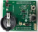
Figure 1. TPL5010EVM
TI's TPL5010EVM evaluation module (EVM) allows a designer to configure the timer intervals of the
TPL5010 and measure its very low current consumption. Moreover, the TPL5010EVM is ready to be
connected to the LaunchPad™ of the MSP430F5529 in order to test its watchdog and timer features. The
EVM has an onboard battery holder (coin battery) to supply the TPL5010 and the microcontroller, if
connected.
The EVM contains one TPL5010 (see Table 1).
Table 1. Device and Package Configurations
2
Device
IC
Package
U1
TPL5010DDC
SOT23-6
TPL5010 Evaluation Module
SNAU173 – January 2015
Submit Documentation Feedback
Copyright © 2015, Texas Instruments Incorporated
�Setup
www.ti.com
2
Setup
Section 2.1 describes the jumpers and connectors on the EVM and Section 2.3 describes how to properly
connect, set up, and use the TPL5010EVM.
See Figure 1 for locations of the top layer jumpers and switches.
2.1
Jumpers and Connectors
Table 2 through Table 5 list the input/output connectors description, jumpers description, switches and
selectors description, and the test points description.
Table 2. Input/Output Connectors Description
Name
Layer
Description
J1/J3
Bottom
2 × 10 pin receptacle to plug the TPL5010EVM into the MSP430F5529 LaunchPad
J4/J2
Bottom
2 × 10 pin receptacle to plug the TPL5010EVM into the MSP430F5529 LaunchPad
RST
Bottom
2-pin receptacle to plug the TPL5010EVM into the MSP430F5529 LaunchPad
VCC
Bottom
2-pin receptacle to plug the TPL5010EVM into the MSP430F5529 LaunchPad
IO
Top
4-pin header connector to bring out RSTn, WAKE, DONE, and GND signals
IO.1
GND
Ground
IO.2
DONE
DONE signal from external microcontroller
IO.3
WAKE
WAKE signal to external microcontroller
IO.4
RSTn
RSTn signal to external microcontroller
Table 3. Jumpers Description
Name
Layer
J1
Top
Description
J1.5–J1.3 shorted, the RSTn pin of the TPL5010 is connected to the gate of Q1 MOSFET.
J1.3–J1.1 shorted, the gate of Q1 MOSFET is connected to VDD (MOSFET OFF).
J1
J1
J1
RSTn
Connected
to Q1
Q1 OFF
RSTn
Connected
to IO
Figure 2. J1 Jumper Setting
J1.6–J1.4 shorted, the WAKE pin of the TPL5010 is connected to the gate of Q2 MOSFET.
J1.4–J1.2 shorted, the gate of Q2 MOSFET is connected to VDD (MOSFET OFF).
J1
J1
J1
WAKE
Connected
to Q2
Q2 OFF
WAKE
Connected
to IO
Figure 3. J1 Jumper Setting
SNAU173 – January 2015
Submit Documentation Feedback
TPL5010 Evaluation Module
Copyright © 2015, Texas Instruments Incorporated
3
�Setup
www.ti.com
Table 3. Jumpers Description (continued)
Name
Layer
J2
Top
Description
In short configuration, the DONE pin of the TPL5010 is connected to the S2 switch with a pull-down
resistor.
J2
J2
DONE
Connected
to S2
DONE
Connected
to IO
Figure 4. J2 Jumper Setting
I_SEL
Top
In open configuration allows the measurement of the current consumption of the TPL5010.
I_SEL
Normal
Operation
I_SEL
TPL5010 Current
Measurement
Figure 5. I_SEL Jumper Setting
R_SEL
Top
Pin1-2 in short configuration, the variable resistance is used to set the timer interval.
Pin2-3 in short configuration, the fix resistance is used to set the timer interval.
R_SEL
R_SEL
Variable
Resistance
Fix
Resistance
Figure 6. R_SEL Jumper Setting
Table 4. Switches and Selectors Description
Name
Layer
Description
S_ON_OFF
Bottom
In ON position turns ON the EVM, in OFF position turns OFF the EVM
S1
Top
When pushed, the SPST switch generates a DONE pulse
S2
Top
When pushed, the SPDT ON/Momentary switch generates a Manual
reset pulse
Table 5. Test Points Description
4
Name
Layer
Description
GND
Top
Test point of the ground, connect the GND of the power supplies
V_BATT
Top
Test point to monitor battery voltage
AUX_VDD
Top
Test point to connect external supply voltage in alternative to the coin
cell battery
TPL5010 Evaluation Module
SNAU173 – January 2015
Submit Documentation Feedback
Copyright © 2015, Texas Instruments Incorporated
�Setup
www.ti.com
2.2
Battery Requirements
In
•
•
•
•
case the EVM is battery powered, the battery must meet the following requirements:
Battery type: CR2032 UL-certified battery
Voltage: 3 V
Minimum capacity: 220 mAh
Minimum discharge rate: N/A mA
NOTE: Only insert DURACELL® 2032 Lithium battery type CR2032, or equivalent.
2.3
TPL5010EVM Configuration
The evaluation board can work standalone or plugged into the MSP430F5529 LaunchPad.
2.3.1
Setting the Time Interval Period
Set the Time interval period by tuning the variable resistance (the trimmer can generate resistances in the
range between 1 kΩ and 200 kΩ).
To
1.
2.
3.
tune the value of the resistance:
Connect a DMM between pin 1 of R_SEL and GND.
Turn the screw on the top of the trimmer until you reach the desired value.
Disconnect the DMM at the end of the operation.
Alternatively, set the DRV pulse interval with the fix resistances (R_EXT1 = 500 Ω, R_EXT2 = 0 Ω). If
required, replace the resistances with customized ones.
See Figure 1 for locations of the resistances REXT1 and REXT2.
SNAU173 – January 2015
Submit Documentation Feedback
TPL5010 Evaluation Module
Copyright © 2015, Texas Instruments Incorporated
5
�Setup
www.ti.com
2.3.2
EVM Standalone Without Microcontroller
The following settings are provided to use the EVM standalone, without a microcontroller:
• Put the S_ON_OFF selector in the OFF position.
• Set the mode of operation through the MODE header (see Table 3).
• Insert a CR2032 coin cell battery in the battery holder (BT), alternatively, connect a voltage source
between the AUX_VDD and GND test points.
• Configure jumper J1 (RSTn connected to Q1, WAKE connected to Q2) and J2 (DONE connected to
S2), as explained in Table 3.
NOTE: Do not connect the coin cell battery and the voltage source to supply the evaluation board at
same time.
•
Put the S_ON_OFF selector in the ON position, or turn on the external voltage source if it is used
instead of the coin cell battery.
The DONE and WAKE signals can be monitored at the IO connector (pin 2 and 3, respectively).
S_ON_OFF
CR2032
I_SEL
J1
R_SEL
J2
xx
xx
xx
x
IO
x
xx
xx
xx
xx
xx
WAKE DONE
Figure 7. Jumpers Configuration – EVM Standalone Without Microcontroller
6
TPL5010 Evaluation Module
SNAU173 – January 2015
Submit Documentation Feedback
Copyright © 2015, Texas Instruments Incorporated
�Setup
www.ti.com
2.3.3
EVM With Microcontroller
The following settings are provided to use the EVM with a microcontroller:
• Put the S_ON_OFF selector in the OFF position.
• Set the mode of operation through the MODE header (see Table 3).
• Connect the microcontroller to the IO header in order to manage the I/O signal of the design under test
(DUT).
• Supply the microcontroller, connecting its supply pin to the AUX_VDD test point and the ground to the
GND pin of the IO header.
• Insert a CR2032 coin cell battery in the battery holder (BT), alternatively, connect a voltage source
between the AUX_VDD and GND test points.
• Configure the jumper J1 (RSTn connected to IO, WAKE connected to IO) and J2 (DONE connected to
IO), as explained in Table 3.
NOTE: Do not connect the coin cell battery and the voltage source to supply the evaluation board at
same time.
Do not use the switch S2 (DONE), in this configuration the DONE switch is connected to a
digital output pin of the microcontroller.
•
Put the S_ON_OFF selector in the ON position, or turn on the external voltage source if it is used
instead of the coin cell battery.
S_ON_OFF
CR2032
I_SEL
J1
R_SEL
VDD
J2
µC
GND GPIO GPIO RST
RSTn
WAKE
DONE
GND
IO
Figure 8. Jumpers Configuration – EVM With Microcontroller
SNAU173 – January 2015
Submit Documentation Feedback
TPL5010 Evaluation Module
Copyright © 2015, Texas Instruments Incorporated
7
�Setup
www.ti.com
2.3.4
EVM With LaunchPad
Load the code from this section into the MSP430F5529 of the LaunchPad. Refer to MSP430 LaunchPad
(MSP-EXP430F5529) Wiki for more details.
• Put the S_ON_OFF selector in the OFF position.
• Set the mode of operation through the MODE header (see Table 3).
• Remove jumpers VCC and RST of the LaunchPad.
• Plug the EVM into the LaunchPad (MSP430F5529), according to the following table:
TPL5010EVM
J1/J3
J4/J2
•
•
MSP430 LaunchPad
J1.1
VDD_µC
pin 4
GND
pin 2
GND
J1/J3
J4/J2
pin 1
3V3
pin 4
GND
pin 2
GND
P2.0
pin 4
WAKE
pin 4
pin 10
RSTn
pin 10
RST
pin 18
DONE
pin 18
P2.3
VCC
3V3
RST
SBW RST
Insert a CR2032 coin cell battery in the battery holder (BT), alternatively, connect a voltage source
between the AUX_VDD and GND test points.
Configure the jumper J1 (RSTn connected to Q1, WAKE connected to Q2) and J2 (DONE connected
to IO), as explained in Table 3.
NOTE: Do not connect the coin cell battery and the voltage source to supply the evaluation board at
the same time.
Do not use the switch S2 (DONE), in this configuration, the DONE switch is connected to a
digital output pin of the microcontroller.
•
Put the S_ON_OFF selector in ON position, or turn on the external voltage source if it is used instead
of the coin cell battery.
S_ON_OFF
CR2032
I_SEL
RST
VCC
J1/J3
J4/J2
J1
R_SEL
J2
Figure 9. Jumpers Configuration – EVM With LaunchPad
8
TPL5010 Evaluation Module
SNAU173 – January 2015
Submit Documentation Feedback
Copyright © 2015, Texas Instruments Incorporated
�Setup
www.ti.com
Example code
Once loaded into the MSP430 of the LaunchPad, the code presented in this section performs the following
features:
• At power on, the green LED present on the LaunchPad is turned on and turned off.
• When the MSP430 receives a RSTn, the red LED is toggled 5 times, then the green LED is turned ON
and OFF and the MSP430 sends a DONE signal to the TPL5010.
• When the MSP430 receives a WAKE pulse, the green LED is turned ON and OFF and the MSP430
sends a DONE signal to the TPL5010.
#include
void main(void) {
WDTCTL = WDTPW | WDTHOLD;
// Stop watchdog timer
P1DIR |= BIT0;
P2DIR |= BIT3;
P4DIR |= BIT7;
// Set P1.0 to output direction
// Set P2.3 to output direction
// Set P4.7 to output direction
P1OUT &= ~BIT0;
P2OUT &= ~BIT3;
P4OUT &= ~BIT7;
// Set P1.0 RED LED OFF
// Set P2.3 DONE Low
// Set P4.7 GREEN LED OFF
P2IES &= ~BIT0;
P2IFG &= ~BIT0;
P2IE |= BIT0;
// P2.0 Lo/Hi edge
// P2.0 IFG Cleared
// P2.0 Interrupt Enabled
SFRRPCR |= SYSNMIIES | SYSNMI;
SFRIE1 |= NMIIE;
//
//
//
//
P4OUT |= BIT7;
__delay_cycles(500000);
P4OUT &= ~BIT7;
// Set P4.7 GREEN LED ON
// Set Delay
// Set P4.7 GREEN LED OFF
P2OUT |= BIT3;
__delay_cycles(100);
P2OUT &= ~BIT3;
// Done High
// Set Delay
// Done Low
Select NMI function for the RST/NMI pin,
interrupt on falling edge
(pull-up R on RST/NMI is already enabled after PUC)
Set NMI pin interrupt enable
__bis_SR_register(LPM4_bits + GIE);
// Enter LPM4
}
// Port 2 interrupt service routine
#pragma vector=PORT2_VECTOR
__interrupt void Port_2(void)
{
volatile unsigned int i;
P4OUT |= BIT7;
i = 10000;
do i--;
while(i != 0);
P4OUT &= ~BIT7;
// GREEN LED ON
// SW Delay
P2OUT |= BIT3;
__delay_cycles(100);
P2OUT &= ~BIT3;
// Done High
// Set Delay
// Done Low
P2IES &= ~BIT0;
P2IFG &= ~BIT0;
P2IE |= BIT0;
// P2.0 Lo/Hi edge
// P2.0 IFG Cleared
// P2.0 Interrupt Enabled
// Set P4.7 GREEN LED OFF
SNAU173 – January 2015
Submit Documentation Feedback
TPL5010 Evaluation Module
Copyright © 2015, Texas Instruments Incorporated
9
�Setup
www.ti.com
}
// User NMI interrupt service routine
#pragma vector=UNMI_VECTOR
__interrupt void UNMI_ISR (void)
{
int n=0;
// Efficiently decode the User NMI interrupt source
switch (__even_in_range(SYSUNIV, SYSUNIV_SYSBUSIV)) {
case SYSUNIV_NMIIFG :
{
for(n=0; n