Sample &
Buy
Product
Folder
Support &
Community
Tools &
Software
Technical
Documents
TPS3779-Q1, TPS3780-Q1
SBVS273A – JUNE 2016 – REVISED SEPTEMBER 2016
TPS37xx-Q1
Dual-Channel, Low-Power, High-Accuracy Voltage Detectors
1 Features
3 Description
•
•
The TPS3779-Q1 and TPS3780-Q1 are a family of
high-accuracy,
two-channel
voltage
detectors
featuring low power and small solution size. The
SENSE1 and SENSE2 inputs include hysteresis to
reject brief glitches, thus ensuring stable output
operation without false triggering. This device family
offers different factory-set hysteresis options of 5% or
10%.
Qualified for Automotive Applications
AEC-Q100 Qualified With the Following Results:
– Device Temperature Grade 1: –40°C to 125°C
Ambient Operating Temperature Range
– Device HBM ESD Classification Level H2
– Device CDM ESD Classification Level C4B
Two-Channel Detectors in Small Packages
High-Accuracy Threshold and Hysteresis: 1.0%
Low Quiescent Current: 2 µA (typ)
Adjustable Detection Voltage Down to 1.2 V
5% and 10% Hysteresis Options
Temperature Range: –40°C to +125°C
Push-Pull (TPS3779-Q1) and Open-Drain
(TPS3780-Q1) Output Options
Available in an SOT-23 Package
1
•
•
•
•
•
•
•
•
2 Applications
•
•
•
•
DSPs, Microcontrollers, and Microprocessors
Advanced Driver Assistance Systems (ADAS)
Infotainment and Clusters
Power-Supply Sequencing Applications
The TPS3779-Q1 and TPS3780-Q1 have adjustable
SENSEx inputs that can be configured by an external
resistor divider. When the voltage at the SENSE1 or
SENSE2 input goes below the falling threshold,
OUT1 or OUT2 is driven low, respectively. When
SENSE1 or SENSE2 rises above the rising threshold,
OUT1 or OUT2 goes high, respectively.
The devices have a very low quiescent current of
2 µA (typical) and provide a precise, space-conscious
solution for voltage detection suitable for low-power,
system-monitoring, and portable applications. The
TPS3779-Q1 and TPS3780-Q1 operate from 1.5 V to
5.5 V, over the –40°C to +125°C temperature range.
Device Information(1)
PART NUMBER
TPS37xx-Q1
PACKAGE
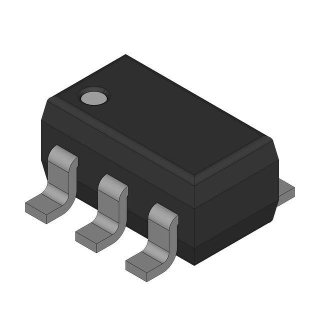
SOT-23 (6)
BODY SIZE (NOM)
2.90 mm × 1.60 mm
(1) For all available packages, see the orderable addendum at
the end of the datasheet.
Sense Threshold (VIT+) Deviation versus
Temperature
Typical Schematic
VDD = 1.5 V to 5.5 V
0.1 F
0.4
Sense 1 VDD = 1.5 V
Sense 1 VDD = 5.5 V
Sense 2 VDD = 1.5 V
Sense 2 VDD = 5.5 V
0.32
VIT+ Deviation (%)
0.24
TPS3780 Only
VMON1
R1
VPULLUP
VDD
RPU1
0.16
VMON2
0.08
R3
0
SENSE1
R2
TPS37xx-Q1
SENSE2
-0.08
R4
-0.16
OUT1
RPU1
OUT2
To a reset or enable
input of the system.
To a reset or enable
input of the system.
GND
Copyright © 2016, Texas Instruments Incorporated
-0.24
-0.32
-0.4
-40
-25
-10
5
20 35 50 65
Temperature (qC)
80
95
110 125
1
An IMPORTANT NOTICE at the end of this data sheet addresses availability, warranty, changes, use in safety-critical applications,
intellectual property matters and other important disclaimers. PRODUCTION DATA.
�TPS3779-Q1, TPS3780-Q1
SBVS273A – JUNE 2016 – REVISED SEPTEMBER 2016
www.ti.com
Table of Contents
1
2
3
4
5
6
7
8
Features ..................................................................
Applications ...........................................................
Description .............................................................
Revision History.....................................................
Device Comparison Table.....................................
Pin Configuration and Functions .........................
Specifications.........................................................
1
1
1
2
3
3
4
7.1
7.2
7.3
7.4
7.5
7.6
7.7
4
4
4
4
5
6
7
Absolute Maximum Ratings ......................................
ESD Ratings..............................................................
Recommended Operating Conditions.......................
Thermal Information ..................................................
Electrical Characteristics...........................................
Timing Requirements ................................................
Typical Characteristics ..............................................
Detailed Description ............................................ 10
8.1 Overview ................................................................. 10
8.2 Functional Block Diagrams ..................................... 10
8.3 Feature Description................................................. 11
8.4 Device Functional Modes........................................ 11
9
Application and Implementation ........................ 12
9.1 Application Information............................................ 12
9.2 Typical Applications ................................................ 13
10 Power-Supply Recommendations ..................... 15
11 Layout................................................................... 15
11.1 Layout Guidelines ................................................. 15
11.2 Layout Example .................................................... 15
12 Device and Documentation Support ................. 16
12.1
12.2
12.3
12.4
12.5
12.6
12.7
12.8
Device Support......................................................
Documentation Support ........................................
Receiving Notification of Documentation Updates
Related Links ........................................................
Community Resources..........................................
Trademarks ...........................................................
Electrostatic Discharge Caution ............................
Glossary ................................................................
16
16
16
16
17
17
17
17
13 Mechanical, Packaging, and Orderable
Information ........................................................... 17
4 Revision History
NOTE: Page numbers for previous revisions may differ from page numbers in the current version.
Changes from Original (June 2016) to Revision A
Page
•
Added TPS3780A-Q1 row to Device Comparison Table ...................................................................................................... 3
•
Added TPS37xxA-Q1 row to VIT– parameter in Electrical Characteristics table..................................................................... 5
2
Submit Documentation Feedback
Copyright © 2016, Texas Instruments Incorporated
Product Folder Links: TPS3779-Q1 TPS3780-Q1
�TPS3779-Q1, TPS3780-Q1
www.ti.com
SBVS273A – JUNE 2016 – REVISED SEPTEMBER 2016
5 Device Comparison Table
PRODUCT
HYSTERESIS (%)
OUTPUT
TPS3779B-Q1
5
Push-pull
TPS3779C-Q1
10
Push-pull
TPS3780A-Q1
0.5
Open-drain
TPS3780B-Q1
5
Open-drain
TPS3780C-Q1
10
Open-drain
6 Pin Configuration and Functions
DBV Package
6-Pin SOT-23
Top View
VDD
1
6
SENSE1
OUT1
2
5
GND
OUT2
3
4
SENSE2
Not to scale
Pin Functions
NAME
GND
OUT1
NO.
I/O
5
—
Ground
O
OUT1 is the output for SENSE1. OUT1 is asserted (driven low) when the voltage at SENSE1 falls below VIT–.
OUT1 is deasserted (goes high) after SENSE1 rises higher than VIT+.
OUT1 is a push-pull output for the TPS3779-Q1 and an open-drain output for the TPS3780-Q1.
The open-drain device (TPS3780-Q1) can be pulled up to 5.5 V independent of VDD; a pullup resistor is
required for this device.
2
DESCRIPTION
OUT2
3
O
OUT2 is the output for SENSE2. OUT2 is asserted (driven low) when the voltage at SENSE2 falls below VIT–.
OUT2 is deasserted (goes high) after SENSE2 rises higher than VIT+.
OUT2 is a push-pull output for the TPS3779-Q1 and an open-drain output for the TPS3780-Q1.
The open-drain device (TPS3780-Q1) can be pulled up to 5.5 V independent of VDD; a pullup resistor is
required for this device.
SENSE1
6
I
This pin is connected to the voltage to be monitored with the use of an external resistor divider.
When the voltage at this pin drops below the threshold voltage (VIT–), OUT1 is asserted.
SENSE2
4
I
This pin is connected to the voltage to be monitored with the use of an external resistor divider.
When the voltage at this pin drops below the threshold voltage (VIT–), OUT2 is asserted.
VDD
1
I
Supply voltage input. Connect a 1.5-V to 5.5-V supply to VDD in order to power the device. Good analog
design practice is to place a 0.1-µF ceramic capacitor close to this pin (required for VDD < 1.5 V).
Submit Documentation Feedback
Copyright © 2016, Texas Instruments Incorporated
Product Folder Links: TPS3779-Q1 TPS3780-Q1
3
�TPS3779-Q1, TPS3780-Q1
SBVS273A – JUNE 2016 – REVISED SEPTEMBER 2016
www.ti.com
7 Specifications
7.1 Absolute Maximum Ratings
over operating junction temperature range (unless otherwise noted) (1)
Voltage
Current
(2)
MAX
–0.3
7
OUT1, OUT2 (TPS3779-Q1 only)
–0.3
VDD + 0.3
OUT1, OUT2 (TPS3780-Q1 only)
–0.3
7
SENSE1, SENSE2
–0.3
7
OUT1, OUT2
Temperature
(1)
MIN
VDD
UNIT
V
±20
Operating junction, TJ (2)
–40
125
Storage, Tstg
–65
150
mA
°C
Stresses beyond those listed under Absolute Maximum Ratings may cause permanent damage to the device. These are stress ratings
only, which do not imply functional operation of the device at these or any other conditions beyond those indicated under Recommended
Operating Conditions. Exposure to absolute-maximum-rated conditions for extended periods may affect device reliability.
For low-power devices, the junction temperature rise above the ambient temperature is negligible; therefore, the junction temperature is
considered equal to the ambient temperature (TJ = TA).
7.2 ESD Ratings
VALUE
V(ESD)
(1)
Human-body model (HBM), per AEC Q100-002
Electrostatic discharge
(1)
UNIT
±2000
Charged-device model (CDM), per AEC Q100-011
V
±500
AEC Q100-002 indicates that HBM stressing shall be in accordance with the ANSI/ESDA/JEDEC JS-001 specification.
7.3 Recommended Operating Conditions
over operating junction temperature range (unless otherwise noted)
MIN
Power-supply voltage
RPU
NOM
MAX
UNIT
1.5
5.5
V
Sense voltage
SENSE1, SENSE2
0
5.5
V
Output voltage (TPS3779-Q1 only)
OUT1, OUT2
0
VDD + 0.3
V
Output voltage (TPS3780-Q1 only)
OUT1, OUT2
0
5.5
1.5
10,000
kΩ
5
mA
Pullup resistor (TPS3780-Q1 only)
Current
CIN
Input capacitor
TJ
Junction temperature
OUT1, OUT2
–5
0.1
–40
25
V
µF
125
°C
7.4 Thermal Information
TPS3779-Q1, TPS3780-Q1
THERMAL METRIC
(1)
DBV (SOT-23)
UNIT
6 PINS
RθJA
Junction-to-ambient thermal resistance
193.9
°C/W
RθJC(top)
Junction-to-case (top) thermal resistance
134.5
°C/W
RθJB
Junction-to-board thermal resistance
39.0
°C/W
ψJT
Junction-to-top characterization parameter
30.4
°C/W
ψJB
Junction-to-board characterization parameter
38.5
°C/W
RθJC(bot)
Junction-to-case (bottom) thermal resistance
N/A
°C/W
(1)
4
For more information about traditional and new thermal metrics, see the Semiconductor and IC Package Thermal Metrics application
report.
Submit Documentation Feedback
Copyright © 2016, Texas Instruments Incorporated
Product Folder Links: TPS3779-Q1 TPS3780-Q1
�TPS3779-Q1, TPS3780-Q1
www.ti.com
SBVS273A – JUNE 2016 – REVISED SEPTEMBER 2016
7.5 Electrical Characteristics
all specifications are over the operating temperature range of –40°C < TJ < +125°C and 1.5 V ≤ VDD ≤ 5.5 V (unless
otherwise noted); typical values are at TJ = 25°C and VDD = 3.3 V
PARAMETER
VDD
V(POR)
TEST CONDITIONS
Input supply range
Power-on-reset voltage
(1)
Supply current (into VDD pin)
VIT+
Positive-going input threshold
voltage
Negative-going input threshold
voltage
VOL (max) = 0.2 V, IOL = 15 µA
VOL
Input current
Low-level output voltage
High-level output voltage
(TPS3779-Q1 only)
Ilkg(OD)
Open-drain output leakage
current (TPS3780-Q1 only)
(1)
V
0.8
V
5.80
VDD = 5.5 V, no load
2.29
6.50
1.194
V(SENSEx) rising
V(SENSEx) falling
–1%
1.188
TPS37xxB-Q1
(5% hysteresis)
1.134
TPS37xxC-Q1
(10% hysteresis)
1.074
–1%
–15
V
V
1%
15
VDD ≥ 1.5 V, ISINK = 0.4 mA
0.25
VDD ≥ 2.7 V, ISINK = 2 mA
0.25
nA
V
0.30
VDD ≥ 1.5 V, ISOURCE = 0.4 mA
0.8 VDD
VDD ≥ 2.7 V, ISOURCE = 1 mA
0.8 VDD
VDD ≥ 4.5 V, ISOURCE = 2.5 mA
0.8 VDD
High impedance, V(SENSEx) = V(OUTx) = 5.5 V
µA
1%
TPS37xxA-Q1
(0.5% hysteresis)
V(SENSEx) = 0 V or VDD
UNIT
5.5
2.09
VDD ≥ 4.5 V, ISINK = 3.2 mA
VOH
MAX
VDD = 3.3 V, no load
V(SENSEx) falling
I(SENSEx)
TYP
1.5
IDD
VIT–
MIN
–250
V
250
nA
Outputs are undetermined below V(POR).
Submit Documentation Feedback
Copyright © 2016, Texas Instruments Incorporated
Product Folder Links: TPS3779-Q1 TPS3780-Q1
5
�TPS3779-Q1, TPS3780-Q1
SBVS273A – JUNE 2016 – REVISED SEPTEMBER 2016
www.ti.com
7.6 Timing Requirements
typical values are at TJ = 25°C and VDD = 3.3 V; SENSEx transitions between 0 V and 1.3 V
MIN
NOM
MAX
UNIT
tPD(r)
SENSEx (rising) to OUTx propagation delay
5.5
µs
tPD(f)
SENSEx (falling) to OUTx propagation delay
10
µs
tSD
Startup delay (1)
570
µs
(1)
During power-on or when a VDD transient is below VDD(min), the outputs reflect the input conditions 570 µs after VDD transitions
through VDD(min).
VDD(min)
VDD
V(POR)
VIT+
SENSEx
VHYS
VIT±
Undefined
OUTx
tSD
tPD(r)
tPD(f)
Undefined
Undefined
570 µs
570 µs
Figure 1. Timing Diagram
6
Submit Documentation Feedback
Copyright © 2016, Texas Instruments Incorporated
Product Folder Links: TPS3779-Q1 TPS3780-Q1
�TPS3779-Q1, TPS3780-Q1
www.ti.com
SBVS273A – JUNE 2016 – REVISED SEPTEMBER 2016
7.7 Typical Characteristics
at TJ = 25°C with a 0.1-µF capacitor close to VDD (unless otherwise noted)
0.4
5
TJ = -40°C
TJ = 0°C
TJ = 25°C
TJ = 85°C
TJ = 105°C
TJ = 125°C
4
0.24
3.5
0.16
3
2.5
2
1.5
0.08
0
-0.08
-0.16
1
-0.24
0.5
-0.32
-0.4
-40
0
0
0.5
1
1.5
2
2.5
3
3.5
Supply Voltage (V)
4
Sense 1 VDD = 1.5 V
Sense 1 VDD = 5.5 V
Sense 2 VDD = 1.5 V
Sense 2 VDD = 5.5 V
0.32
VIT+ Deviation (%)
Supply Current (PA)
4.5
4.5
5
5.5
-25
-10
5
20 35 50 65
Temperature (qC)
80
95
110 125
SENSE1 = SENSE2 = 1.5 V
Figure 2. Supply Current vs Supply Voltage
Figure 3. Sense Threshold (VIT+) Deviation vs Temperature
0.4
4500
Sense 1 VDD = 1.5 V
Sense 1 VDD = 5.5 V
Sense 2 VDD = 1.5 V
Sense 2 VDD = 5.5 V
0.32
0.24
4000
3500
VIT- Deviation (%)
0.16
3000
Count
0.08
0
2500
2000
-0.08
1500
-0.16
1000
-0.24
500
-0.32
1
0.8
0
0.6
110 125
0.4
95
0.2
80
-0.2
20 35 50 65
Temperature (qC)
-0.4
5
-0.6
-10
-0.8
-25
-1
0
-0.4
-40
VIT+ Accuracy (%)
VDD = 5.5 V
Figure 4. Sense Threshold (VIT–) Deviation vs Temperature
Figure 5. Sense Threshold (VIT+)
5500
5000
4500
4000
VOL (V)
Count
3500
3000
2500
2000
1500
1000
500
1
0.8
0.6
0.4
0.2
0
-0.2
-0.4
-0.6
-0.8
-1
0
1.3
1.2
1.1
1
0.9
0.8
0.7
0.6
0.5
0.4
0.3
0.2
0.1
0
TJ = -40°C
TJ = 0°C
0
1
VIT- Accuracy (%)
TJ = 25°C
TJ = 85°C
TJ = 105°C
TJ = 125°C
2
3
Output Sink Current (mA)
4
5
VDD = 5.5 V
Figure 6. Sense Threshold (VIT–)
Figure 7. Output Voltage Low vs Output Current
(VDD = 1.5 V)
Submit Documentation Feedback
Copyright © 2016, Texas Instruments Incorporated
Product Folder Links: TPS3779-Q1 TPS3780-Q1
7
�TPS3779-Q1, TPS3780-Q1
SBVS273A – JUNE 2016 – REVISED SEPTEMBER 2016
www.ti.com
Typical Characteristics (continued)
at TJ = 25°C with a 0.1-µF capacitor close to VDD (unless otherwise noted)
0.5
0.5
TJ = -40°C
TJ = 0°C
TJ = 25°C
TJ = -40°C
TJ = 0°C
TJ = 25°C
0.4
0.3
VOL (V)
VOL (V)
0.4
TJ = 85°C
TJ = 105°C
TJ = 125°C
0.2
0.1
0.3
0.2
0.1
0
0
0
1
2
3
Output Sink Current (mA)
4
5
0
Figure 8. Output Voltage Low vs Output Current
(VDD = 3.3 V)
1
2
3
Output Sink Current (mA)
4
5
Figure 9. Output Voltage Low vs Output Current
(VDD = 5.5 V)
3.75
1.7
TJ = -40°C
TJ = 0°C
1.6
TJ = 25°C
TJ = 85°C
TJ = 105°C
TJ = 125°C
TJ = -40°C
TJ = 0°C
3.5
1.5
TJ = 25°C
TJ = 85°C
TJ = 105°C
TJ = 125°C
3.25
1.4
3
1.3
VOH (V)
VOH (V)
TJ = 85°C
TJ = 105°C
TJ = 125°C
1.2
1.1
2.75
2.5
2.25
1
0.9
2
0.8
1.75
0.7
0.1
1.5
0.2
0.3
0.4
0.5
0.6
Output Source Current (mA)
0.7
0
0.8
Figure 10. Output Voltage High vs Output Current
(VDD = 1.5 V)
0.5
1
1.5
2
2.5
3
3.5
Output Source Current (mA)
4
4.5
5
Figure 11. Output Voltage High vs Output Current
(VDD = 3.3 V)
6.1
5.75
TJ = -40°C
TJ = 0°C
TJ = 25°C
TJ = 85°C
TJ = 105°C
TJ = 125°C
5.9
5.5
tPD(r) (µs)
VOH (V)
5.7
5.25
5
5.5
5.3
5.1
4.75
4.9
4.5
0
0.5
1
1.5
2
2.5
3
3.5
Output Source Current (mA)
4
4.5
5
4.7
-40
Sense 1 VDD = 1.5 V
Sense 1 VDD = 5.5 V
-25
-10
5
Sense 2 VDD = 1.5 V
Sense 2 VDD = 5.5 V
20 35 50 65
Temperature (qC)
80
95
110 125
SENSE1 = SENSE2 = 0 V to 1.3 V
Figure 12. Output Voltage High vs Output Current
(VDD = 5.5 V)
8
Figure 13. Propagation Delay from
SENSEx High to Output High
Submit Documentation Feedback
Copyright © 2016, Texas Instruments Incorporated
Product Folder Links: TPS3779-Q1 TPS3780-Q1
�TPS3779-Q1, TPS3780-Q1
www.ti.com
SBVS273A – JUNE 2016 – REVISED SEPTEMBER 2016
Typical Characteristics (continued)
at TJ = 25°C with a 0.1-µF capacitor close to VDD (unless otherwise noted)
14
1150
VDD = 1.5 V
VDD = 5.5 V
1050
950
Startup Delay (Ps)
tPD(f) (µs)
12
10
8
850
750
650
550
450
6
Sense 1 VDD = 1.5 V
Sense 1 VDD = 5.5 V
4
-40
-25
-10
5
Sense 2 VDD = 1.5 V
Sense 2 VDD = 5.5 V
20 35 50 65
Temperature (qC)
80
95
350
250
-40
110 125
-25
-10
5
20 35 50 65
Temperature (qC)
80
95
110 125
SENSE1 = SENSE2 = 1.3 V to 0 V
Figure 14. Propagation Delay from
SENSEx Low to Output Low
Figure 15. Startup Delay
55
55
TJ = -40°C
TJ = 0°C
TJ = +25°C
TJ = +85°C
TJ = +105°C
TJ = +125°C
Transient Duration (Ps)
45
40
35
TJ = -40°C
TJ = 0°C
TJ = +25°C
TJ = +85°C
TJ = +105°C
TJ = +125°C
50
45
Transient Duration (Ps)
50
30
25
20
15
40
35
30
25
20
15
10
10
5
5
0
0
0
3
6
9
12
15
18
Overdrive (%)
21
24
27
30
0
High-to-low transition occurs above the curve
3
6
9
12
15
18
Overdrive (%)
21
24
9
12
15
18
Overdrive (%)
21
24
27
30
27
Figure 17. Minimum Transient Duration vs Overdrive
(VDD = 5.5 V)
Transient Duration (Ps)
Transient Duration (Ps)
TJ = -40°C
TJ = 0°C
TJ = +25°C
TJ = +85°C
TJ = +105°C
TJ = +125°C
0
6
High-to-low transition occurs above the curve
Figure 16. Minimum Transient Duration vs Overdrive
(VDD = 1.5 V)
35
32.5
30
27.5
25
22.5
20
17.5
15
12.5
10
7.5
5
2.5
0
3
30
Low-to-high transition occurs above the curve
Figure 18. Minimum Transient Duration vs Overdrive
(VDD = 1.5 V)
35
32.5
30
27.5
25
22.5
20
17.5
15
12.5
10
7.5
5
2.5
0
TJ = -40°C
TJ = 0°C
TJ = +25°C
TJ = +85°C
TJ = +105°C
TJ = +125°C
0
3
6
9
12
15
18
Overdrive (%)
21
24
27
30
Low-to-high transition occurs above the curve
Figure 19. Minimum Transient Duration vs Overdrive
(VDD = 5.5 V)
Submit Documentation Feedback
Copyright © 2016, Texas Instruments Incorporated
Product Folder Links: TPS3779-Q1 TPS3780-Q1
9
�TPS3779-Q1, TPS3780-Q1
SBVS273A – JUNE 2016 – REVISED SEPTEMBER 2016
www.ti.com
8 Detailed Description
8.1 Overview
The TPS3779-Q1 and TPS3780-Q1 are small, low quiescent current (IDD), dual-channel voltage detectors. These
devices have high-accuracy rising and falling input thresholds, and assert the output as shown in Table 1. The
output (OUTx pin) goes low when the SENSEx pin is less than VIT– and goes high when the pin is greater than
VIT+. The TPS3779-Q1 and TPS3780-Q1 offer two hysteresis options (5% and 10%) for use in a wide variety of
applications. These devices have two independent voltage-detection channels that can be used in systems
where multiple voltage rails are required to be monitored, or where one channel can be used as an early warning
signal and the other channel can be used as the system reset signal.
Table 1. TPS3779-Q1, TPS3780-Q1 Truth Table
CONDITIONS
OUTPUT
SENSE1 < VIT–
OUT1 = low
SENSE2 < VIT–
OUT2 = low
SENSE1 > VIT+
OUT1 = high
SENSE2 > VIT+
OUT2 = high
8.2 Functional Block Diagrams
VDD
VDD
SENSE1
SENSE2
OUT1
SENSE1
OUT2
SENSE2
OUT1
OUT2
VIT+
VIT+
TPS3779-Q1
GND
Copyright © 2016, Texas Instruments Incorporated
Figure 20. TPS3779-Q1 Block Diagram
10
TPS3780-Q1
GND
Copyright © 2016, Texas Instruments Incorporated
Figure 21. TPS3780-Q1 Block Diagram
Submit Documentation Feedback
Copyright © 2016, Texas Instruments Incorporated
Product Folder Links: TPS3779-Q1 TPS3780-Q1
�TPS3779-Q1, TPS3780-Q1
www.ti.com
SBVS273A – JUNE 2016 – REVISED SEPTEMBER 2016
8.3 Feature Description
8.3.1 Inputs (SENSE1, SENSE2)
The TPS3779-Q1 and TPS3780-Q1 each have two comparators for voltage detection. Each comparator has one
external input; the other input is connected to the internal reference. The comparator rising threshold is designed
and trimmed to be equal to VIT+, and the falling threshold is trimmed to be equal to VIT–. The built-in falling
hysteresis options make the devices immune to supply rail noise and ensure stable operation.
The comparator inputs can swing from ground to 5.5 V, regardless of the device supply voltage used. Although
not required in most cases, for extremely noisy applications, good analog design practice is to place a 1-nF to
10-nF bypass capacitor at the comparator input in order to reduce sensitivity to transients and layout parasitic.
For each SENSEx input, the corresponding output (OUTx) is driven to logic low when the input voltage drops
below VIT–. When the voltage exceeds VIT+, the output (OUTx) is driven high; see Figure 1.
8.3.2 Outputs (OUT1, OUT2)
In a typical device application, the outputs are connected to a reset or enable input of another device, such as a
digital signal processor (DSP), central processing unit (CPU), field-programmable gate array (FPGA), or
application-specific integrated circuit (ASIC); or the outputs are connected to the enable input of a voltage
regulator, such as a dc-dc or low-dropout (LDO) regulator.
The TPS3779-Q1 provides two push-pull outputs. The logic high level of the outputs is determined by the VDD
pin voltage. Pullup resistors are not required with this configuration, thus saving board space. However, all
interface logic levels must be examined. All OUTx connections must be compatible with the VDD pin logic level.
The TPS3780-Q1 provides two open-drain outputs (OUT1 and OUT2); pullup resistors must be used to hold
these lines high when the output goes to a high-impedance condition (not asserted). By connecting pullup
resistors to the proper voltage rails, the outputs can be connected to other devices at correct interface voltage
levels. The outputs can be pulled up to 5.5 V, independent of the device supply voltage. To ensure proper
voltage levels, make sure to choose the correct pullup resistor values. The pullup resistor value is determined by
VOL, the sink current capability, and the output leakage current (Ilkg(OD)). These values are specified in the
Electrical Characteristics table. By using wired-AND logic, OUT1 and OUT2 can be combined into one logic
signal. The Inputs (SENSE1, SENSE2) section describes how the outputs are asserted or deasserted. See
Figure 1 for a description of the relationship between threshold voltages and the respective output.
8.4 Device Functional Modes
8.4.1 Normal Operation (VDD ≥ VDD(min))
When the voltage on VDD is greater than VDD(min) for tSD, the output signals react to the present state of the
corresponding SENSEx pins.
8.4.2 Power-On-Reset (VDD < V(POR))
When the voltage on VDD is lower than the required voltage to internally pull the logic low output to GND
(V(POR)), both outputs are undefined and are not to be relied upon for proper system function.
Submit Documentation Feedback
Copyright © 2016, Texas Instruments Incorporated
Product Folder Links: TPS3779-Q1 TPS3780-Q1
11
�TPS3779-Q1, TPS3780-Q1
SBVS273A – JUNE 2016 – REVISED SEPTEMBER 2016
www.ti.com
9 Application and Implementation
NOTE
Information in the following applications sections is not part of the TI component
specification, and TI does not warrant its accuracy or completeness. TI’s customers are
responsible for determining suitability of components for their purposes. Customers should
validate and test their design implementation to confirm system functionality.
9.1 Application Information
The TPS3779-Q1 and TPS3780-Q1 are used as precision, dual-voltage detectors. The monitored voltage, VDD
voltage, and output pullup voltage (TPS3780-Q1 only) can be independent voltages or connected in any
configuration.
9.1.1 Threshold Overdrive
Threshold overdrive is how much VSENSE1 or VSENSE2 exceeds the specified threshold, and is important to know
because a smaller overdrive results in a slower OUTx response. Threshold overdrive is calculated as a percent
of the threshold in question, as shown in Equation 1:
Overdrive = | (VSENSE1,2 / VIT – 1) × 100% |
where
•
•
VIT is either VIT– or VIT+, depending on whether calculating the overdrive for the negative-going threshold or the
positive-going threshold, respectively
VSENSE1,2 is the voltage at the SENSE1 or SENSE2 input
(1)
Figure 16 illustrates the minimum detectable pulse on the SENSEx inputs versus overdrive, and is used to
visualize the relationship that overdrive has on tPD(f) for negative-going events.
9.1.2 Sense Resistor Divider
The resistor divider values and target threshold voltage can be calculated by using Equation 2 and Equation 3 to
determine VMON(UV) and VMON(PG), respectively.
R1 ·
§
VMON(UV) = ¨ 1 +
× VIT
R2 ¸¹
©
(2)
R1 ·
§
VMON(PG) = ¨ 1 +
× VIT+
R2 ¸¹
©
(3)
where
•
•
•
R1 and R2 are the resistor values for the resistor divider on the SENSEx pins
VMON(UV) is the target voltage at which an undervoltage condition is detected
VMON(PG) is the target voltage at which the output goes high when VMONx rises
Choose RTOTAL (equal to R1 + R2) so that the current through the divider is approximately 100 times higher than
the input current at the SENSEx pins. The resistors can have high values to minimize current consumption as a
result of low input bias current without adding significant error to the resistive divider. For details on sizing input
resistors, see the Optimizing Resistor Dividers at a Comparator Input application report (SLVA450), available for
download from www.ti.com.
12
Submit Documentation Feedback
Copyright © 2016, Texas Instruments Incorporated
Product Folder Links: TPS3779-Q1 TPS3780-Q1
�TPS3779-Q1, TPS3780-Q1
www.ti.com
SBVS273A – JUNE 2016 – REVISED SEPTEMBER 2016
9.2 Typical Applications
9.2.1 Monitoring Two Separate Rails
VDD = 5 V
0.1 F
VMON1
R1
VPULLUP
VDD
RPU1
VMON2
SENSE1
R3
R2
OUT1
TPS3780C-Q1
SENSE2
R4
RPU1
OUT2
To a reset or enable
input of the system.
To a reset or enable
input of the system.
GND
Copyright © 2016, Texas Instruments Incorporated
Figure 22. Monitoring Two Separate Rails Schematic
9.2.1.1 Design Requirements
Table 2. Design Parameters
PARAMETER
DESIGN REQUIREMENT
DESIGN RESULT
VDD
5V
5V
Hysteresis
10%
10%
Monitored voltage 1
3.3 V nominal, VMON(PG) = 2.9 V,
VMON(UV) = 2.6 V
VMON(PG) = 2.908 V, VMON(UV) = 2.618 V
Monitored voltage 2
3 V nominal, VMON(PG) = 2.6 V,
VMON(UV) = 2.4 V
VMON(PG) = 2.606 V, VMON(UV) = 2.371 V
Output logic voltage
3.3-V CMOS
3.3-V CMOS
9.2.1.2 Detailed Design Procedure
1. Select the TPS3780C-Q1. The C version is selected to satisfy the hysteresis requirement. The TPS3780-Q1
is selected for the output logic requirement. An open-drain output allows for the output to be pulled up to a
voltage other than VDD.
2. The resistor divider values are calculated by using Equation 2 and Equation 3. For SENSE1, R1 = 1.13 MΩ
and R2 = 787 kΩ. For SENSE2, R3 (R1) = 681 kΩ and R4 (R2) = 576 kΩ.
9.2.1.3 Application Curve
VMON1 (500 mV/div)
VMON2(500 mV/div)
OUT1 (1 V/div)
OUT2 (1 V/div)
Time (5 ms/div)
Figure 23. Monitoring Two Separate Rails Curve
Submit Documentation Feedback
Copyright © 2016, Texas Instruments Incorporated
Product Folder Links: TPS3779-Q1 TPS3780-Q1
13
�TPS3779-Q1, TPS3780-Q1
SBVS273A – JUNE 2016 – REVISED SEPTEMBER 2016
www.ti.com
9.2.2 Early Warning Detection
VMON
0.1 F
R1
VDD
SENSE1
R2
To a reset or enable
input of the system.
TPS3779C-Q1
SENSE2
R3
OUT1
OUT2
To a reset or enable
input of the system.
GND
Copyright © 2016, Texas Instruments Incorporated
Figure 24. Early Warning Detection Schematic
9.2.2.1 Design Requirements
Table 3. Design Parameters
PARAMETER
DESIGN REQUIREMENT
DESIGN RESULT
VMON
VDD
VMON
Hysteresis
10%
10%
Monitored voltage 1
VMON(PG) = 3.3 V, VMON(UV) = 3 V
VMON(PG) = 3.330 V, VMON(UV) = 2.997 V
Monitored voltage 2
VMON(PG) = 3.9 V, VMON(UV) = 3.5 V
VMON(PG) = 3.921 V, VMON(UV) = 3.529 V
9.2.2.2 Detailed Design Procedure
1. Select the TPS3779C-Q1. The C version is selected to satisfy the hysteresis requirement. The TPS3779-Q1
is selected to save on component count and board space.
2. Use Equation 4 to calculate the total resistance for the resistor divider. Determine the minimum total
resistance of the resistor network necessary to achieve the current consumption specification. For this
example, the current flow through the resistor network is chosen to be 1.41 µA. Use the key transition point
for VMON2. For this example, the low-to-high transition, VMON(PG), is considered more important.
VMON(PG _ 2)
3.9 V
RTOTAL
2.78 M:
I
1.41 $
where
•
•
VMON(PG_2) is the target voltage at which OUT2 goes high when VMON rises
I is the current flowing through the resistor network
(4)
3. After RTOTAL is determined, R3 can be calculated using Equation 5. Select the nearest 1% resistor value for
R3. In this case, 845 kΩ is the closest value.
VIT+ 1.194 V
R3
846 k:
I
1.41 A
(5)
4. Use Equation 6 to calculate R2. Select the nearest 1% resistor value for R2. In this case, 150 kΩ is the
closest value. Use the key transition point for VMON1. For this example, the high-to-low transition, VMON(UV), is
considered more important.
RTOTAL
2.78 M:
R2
R3
x VIT
x 1.074 V 845 k: 149 k:
VMON(UV _ 1)
3V
where
•
14
VMON(UV_1) is the target voltage at which OUT1 goes low when VMON falls
Submit Documentation Feedback
(6)
Copyright © 2016, Texas Instruments Incorporated
Product Folder Links: TPS3779-Q1 TPS3780-Q1
�TPS3779-Q1, TPS3780-Q1
www.ti.com
SBVS273A – JUNE 2016 – REVISED SEPTEMBER 2016
5. Use Equation 7 to calculate R1. Select the nearest 1% resistor value for R1. In this case, 1.78 MΩ is a 1%
resistor.
R1 RTOTAL R2 R3 2.78 M: 150 k: 845 k: 1.78 M:
(7)
9.2.2.3 Application Curve
VDD = VMON (1 V/div)
OUT1 (1 V/div)
OUT2 (1 V/div)
Time (5 ms/div)
Figure 25. Early Warning Detection Curve
10 Power-Supply Recommendations
The TPS3779-Q1 and TPS3780-Q1 are designed to operate from an input voltage supply range between 1.5 V
and 5.5 V. An input supply capacitor is not required for this device; however, good analog practice is to place a
0.1-µF or greater capacitor between the VDD pin and the GND pin. This device has a 7-V absolute maximum
rating on the VDD pin. If the voltage supply providing power to VDD is susceptible to any large voltage transient
that can exceed 7 V, additional precautions must be taken.
For applications where SENSEx is greater than 0 V before VDD, and is subject to a startup slew rate of less than
200 mV per 1 ms, the output can be driven to logic high in error. To correct the output, cycle the SENSEx lines
below VIT– or sequence SENSEx after VDD.
11 Layout
11.1 Layout Guidelines
Place the VDD decoupling capacitor close to the device.
Avoid using long traces for the VDD supply node. The VDD capacitor, along with parasitic inductance from the
supply to the capacitor, can form an LC tank circuit that creates ringing with peak voltages above the maximum
VDD voltage.
11.2 Layout Example
CIN
VDD
VMON1
R1
VPU
1
6
OUT1
2
5
OUT2
3
4
R5
R2
R4
R6
VPU
R3
VMON2
Figure 26. Example SOT-23 Layout
Submit Documentation Feedback
Copyright © 2016, Texas Instruments Incorporated
Product Folder Links: TPS3779-Q1 TPS3780-Q1
15
�TPS3779-Q1, TPS3780-Q1
SBVS273A – JUNE 2016 – REVISED SEPTEMBER 2016
www.ti.com
12 Device and Documentation Support
12.1 Device Support
12.1.1 Development Support
12.1.1.1 Evaluation Modules
An evaluation module (EVM) is available to assist in the initial circuit performance evaluation using the TPS3779Q1 and TPS3780-Q1. The TPS3780EVM-154 Evaluation Module details the design kits and evaluation modules
for the TPS3780EVM-154.
The EVM can be requested at Texas Instruments through the TPS3779-Q1 and TPS3780-Q1 product folders, or
purchased directly from the TI eStore.
12.1.1.2 Spice Models
Computer simulation of circuit performance using SPICE is often useful when analyzing the performance of
analog circuits and systems. A SPICE model for the TPS3779-Q1 and TPS3780-Q1 is available through the
respective device product folders under Simulation Models.
12.1.2 Device Nomenclature
The TPS3779xQyyyzQ1 and TPS3780xQyyyzQ1 are the generic naming conventions for these devices. The
TPS3779-Q1 and TPS3780-Q1 represent the family of these devices; x is used to display the hysteresis version,
yyy is reserved for the package designator, and z is the package quantity.
• Example: TPS3780CDBVRQ1
• Family: TPS3780-Q1 (open-drain)
• Hysteresis: 10%
• DBV package: 6-pin SOT-23
• Package quantity: R is for 3000 pieces
12.2 Documentation Support
12.2.1 Related Documentation
For related documentation see the following:
• TPS3780EVM-154 Evaluation Module (SLVU796)
• Optimizing Resistor Dividers at a Comparator Input Application Report (SLVA450)
12.3 Receiving Notification of Documentation Updates
To receive notification of documentation updates, navigate to the device product folder on ti.com. In the upper
right corner, click on Alert me to register and receive a weekly digest of any product information that has
changed. For change details, review the revision history included in any revised document.
12.4 Related Links
The table below lists quick access links. Categories include technical documents, support and community
resources, tools and software, and quick access to sample or buy.
Table 4. Related Links
16
PARTS
PRODUCT FOLDER
SAMPLE & BUY
TECHNICAL
DOCUMENTS
TOOLS &
SOFTWARE
SUPPORT &
COMMUNITY
TPS3779-Q1
Click here
Click here
Click here
Click here
Click here
TPS3780-Q1
Click here
Click here
Click here
Click here
Click here
Submit Documentation Feedback
Copyright © 2016, Texas Instruments Incorporated
Product Folder Links: TPS3779-Q1 TPS3780-Q1
�TPS3779-Q1, TPS3780-Q1
www.ti.com
SBVS273A – JUNE 2016 – REVISED SEPTEMBER 2016
12.5 Community Resources
The following links connect to TI community resources. Linked contents are provided "AS IS" by the respective
contributors. They do not constitute TI specifications and do not necessarily reflect TI's views; see TI's Terms of
Use.
TI E2E™ Online Community TI's Engineer-to-Engineer (E2E) Community. Created to foster collaboration
among engineers. At e2e.ti.com, you can ask questions, share knowledge, explore ideas and help
solve problems with fellow engineers.
Design Support TI's Design Support Quickly find helpful E2E forums along with design support tools and
contact information for technical support.
12.6 Trademarks
E2E is a trademark of Texas Instruments.
All other trademarks are the property of their respective owners.
12.7 Electrostatic Discharge Caution
This integrated circuit can be damaged by ESD. Texas Instruments recommends that all integrated circuits be handled with
appropriate precautions. Failure to observe proper handling and installation procedures can cause damage.
ESD damage can range from subtle performance degradation to complete device failure. Precision integrated circuits may be more
susceptible to damage because very small parametric changes could cause the device not to meet its published specifications.
12.8 Glossary
SLYZ022 — TI Glossary.
This glossary lists and explains terms, acronyms, and definitions.
13 Mechanical, Packaging, and Orderable Information
The following pages include mechanical, packaging, and orderable information. This information is the most
current data available for the designated devices. This data is subject to change without notice and revision of
this document. For browser-based versions of this data sheet, refer to the left-hand navigation.
Submit Documentation Feedback
Copyright © 2016, Texas Instruments Incorporated
Product Folder Links: TPS3779-Q1 TPS3780-Q1
17
�PACKAGE OPTION ADDENDUM
www.ti.com
10-Dec-2020
PACKAGING INFORMATION
Orderable Device
Status
(1)
Package Type Package Pins Package
Drawing
Qty
Eco Plan
(2)
Lead finish/
Ball material
MSL Peak Temp
Op Temp (°C)
Device Marking
(3)
(4/5)
(6)
TPS3779BQDBVRQ1
ACTIVE
SOT-23
DBV
6
3000
RoHS & Green
NIPDAU
Level-2-260C-1 YEAR
-40 to 125
12OE
TPS3779CQDBVRQ1
ACTIVE
SOT-23
DBV
6
3000
RoHS & Green
NIPDAU
Level-2-260C-1 YEAR
-40 to 125
12PE
TPS3780AQDBVRQ1
ACTIVE
SOT-23
DBV
6
3000
RoHS & Green
NIPDAU
Level-2-260C-1 YEAR
-40 to 125
12FE
TPS3780BQDBVRQ1
ACTIVE
SOT-23
DBV
6
3000
RoHS & Green
NIPDAU
Level-2-260C-1 YEAR
-40 to 125
12GE
TPS3780CQDBVRQ1
ACTIVE
SOT-23
DBV
6
3000
RoHS & Green
NIPDAU
Level-2-260C-1 YEAR
-40 to 125
12HE
(1)
The marketing status values are defined as follows:
ACTIVE: Product device recommended for new designs.
LIFEBUY: TI has announced that the device will be discontinued, and a lifetime-buy period is in effect.
NRND: Not recommended for new designs. Device is in production to support existing customers, but TI does not recommend using this part in a new design.
PREVIEW: Device has been announced but is not in production. Samples may or may not be available.
OBSOLETE: TI has discontinued the production of the device.
(2)
RoHS: TI defines "RoHS" to mean semiconductor products that are compliant with the current EU RoHS requirements for all 10 RoHS substances, including the requirement that RoHS substance
do not exceed 0.1% by weight in homogeneous materials. Where designed to be soldered at high temperatures, "RoHS" products are suitable for use in specified lead-free processes. TI may
reference these types of products as "Pb-Free".
RoHS Exempt: TI defines "RoHS Exempt" to mean products that contain lead but are compliant with EU RoHS pursuant to a specific EU RoHS exemption.
Green: TI defines "Green" to mean the content of Chlorine (Cl) and Bromine (Br) based flame retardants meet JS709B low halogen requirements of