Product
Folder
Order
Now
Technical
Documents
Support &
Community
Tools &
Software
Reference
Design
TPS51716
ZHCSAF5A – OCTOBER 2012 – REVISED SEPTEMBER 2016
具有同步降压控制器、2A LDO 和缓冲基准的 TPS51716 完整 DDR2、
、
DDR3、
、DDR3L、
、LPDDR3 和 DDR4 内存电源解决方案
1 特性
•
1
•
•
•
同步降压控制器 (VDDQ)
– 转换电压范围:3V 至 28V
– 输出电压范围:0.7V 至 1.8V
– 0.8% VREF精度
– D-CAP2™针对陶瓷输出电容器的模式
– 可选 500kHz/670kHz 开关频率
– 自动跳频功能优化了轻负载和重负载时的效率
– 支持 S4/S5 状态中的软启动
– 过流 (OCL) / 过压 (OVP) / 欠压 (UVP) / 欠压闭
锁 (UVLO) 保护
– 电源正常输出
2A LDO (VTT)、缓冲基准 (VTTREF)
– 2A(峰值)灌电流和拉电流
– 只需 10μF 陶瓷输出电容器
– 经缓冲的,低噪声,10mA VTTREF 输出
– 0.8% VTTREF,20mV VTT 精度
– 在 S3 中支持高阻抗 (High-Z) 而在 S4/S5 中支
持软关闭
热关断
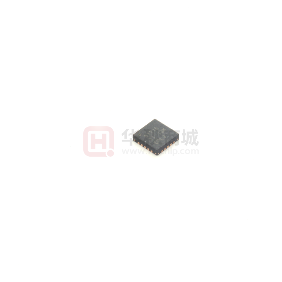
20 引脚 3mm × 3mm WQFN 封装
3 说明
TPS51716 用最少总体成本和最小空间提供一个用于
DDR2、DDR3、DDR3L、LPDDR3 和 DDR4 内存系
统的完整电源。它将同步降压稳压器控制器 (VDDQ)
与 2A 灌电流/拉电流跟踪 LDO (VTT) 和缓冲低噪声基
准 (VTTREF) 相集成。TPS51716 采用融合了 500kHz
或 670kHz 工作频率的 D-CAP2 模式,此模式可在无
需外部补偿电路的情况下支持陶瓷输出电容器。
VTTREF 跟踪 VDDQ/2 的精度高达 0.8%。能够提供
2A 灌电流/拉电流峰值电流功能的 VTT ,而且只需
10μF 的陶瓷电容。此外,该器件还 具有 专用 LDO 电
源输入。
TPS51716 提供丰富、实用的功能以及出色的电源性
能。它支持灵活功率级控制,将 VTT 置于 S3 中的高
阻抗状态并在 S4/S5 状态中将 VDDQ,VTT 和
VTTREF 放电(软关闭)。它包括具有低侧 MOSFET
RDS(接通)感测的可编程 OCL,OVP/UVP/UVLO 和热
关断保护。
TI 的 TPS51716 采用 20 引脚 3mm × 3mm WQFN 封
装,且其额定环境温度范围介于 -40°C 至 85°C 之
间。
2 应用
•
•
DDR2、DDR3、DDR3L、LPDDR3 和 DDR4 内存
电源
SSTL_18、SSTL_15、SSTL_135 和 HSTL 终端
器件信息(1)
器件型号
封装
TPS51716
封装尺寸(标称值)
WQFN (20)
3.00mm x 3.00mm
(1) 如需了解所有可用封装,请参阅数据表末尾的可订购产品附
录。
框图
VIN
5VIN
PGND
PGND
TPS51716
VBST 15
12 V5IN
S3
17 S3
S5
16 S5
VDDQ
DRVH 14
SW 13
DRVL 11
6
VREF
PGND 10
PGOOD 20
8
REFIN
7
GND
VDDQSNS
9
VLDOIN
2
VTT
3
19 MODE
VTTSNS
1
18 TRIP
VTTGND
4
VTTREF
5
Powergood
VTT
VTTREF
UDG-12146
AGND PGND
AGND
PGND
Copyright © 2016, Texas Instruments Incorporated
1
An IMPORTANT NOTICE at the end of this data sheet addresses availability, warranty, changes, use in safety-critical applications,
intellectual property matters and other important disclaimers. PRODUCTION DATA.
English Data Sheet: SLUSB94
�TPS51716
ZHCSAF5A – OCTOBER 2012 – REVISED SEPTEMBER 2016
www.ti.com.cn
目录
1
2
3
4
5
6
7
特性 ..........................................................................
应用 ..........................................................................
说明 ..........................................................................
修订历史记录 ...........................................................
Pin Configuration and Functions .........................
Specifications.........................................................
1
1
1
2
3
4
6.1
6.2
6.3
6.4
6.5
6.6
4
4
5
5
6
8
Absolute Maximum Ratings ......................................
ESD Ratings..............................................................
Recommended Operating Conditions.......................
Thermal Information ..................................................
Electrical Characteristics...........................................
Typical Characteristics ..............................................
Detailed Description ............................................ 12
7.1 Overview ................................................................. 12
7.2 Functional Block Diagram ....................................... 12
7.3 Feature Description................................................. 13
7.4 Device Functional Modes........................................ 16
8
Application and Implementation ........................ 18
8.1 Application Information............................................ 18
8.2 Typical Application ................................................. 18
9 Power Supply Recommendations...................... 22
10 Layout................................................................... 23
10.1 Layout Guidelines ................................................. 23
10.2 Layout Example .................................................... 24
11 器件和文档支持 ..................................................... 25
11.1
11.2
11.3
11.4
11.5
器件支持................................................................
文档支持................................................................
商标 .......................................................................
静电放电警告.........................................................
Glossary ................................................................
25
25
25
25
25
12 机械、封装和可订购信息 ....................................... 25
4 修订历史记录
注:之前版本的页码可能与当前版本有所不同。
Changes from Original (October 2012) to Revision A
Page
•
添加了 ESD 额定值 表、详细 说明部分,应用和实施部分,电源相关建议部分,布局部分,器件和文档支持部分以及
机械、封装和可订购信息部分 ................................................................................................................................................. 1
•
将标题从“完整 DDR2、DDR3、DDR3L 和 LPDDR3 内存电源解决方案”更新为“完整 DDR2、DDR3、DDR3L、
LPDDR3 和 DDR4 内存电源解决方案” ................................................................................................................................... 1
•
在应用 列表中将“DDR2/DDR3/DDR3L/LPDDR3 内存电源”更改为“DDR2、DDR3、DDR3L、LPDDR3 和 DDR4 内存
电源” ....................................................................................................................................................................................... 1
2
Copyright © 2012–2016, Texas Instruments Incorporated
�TPS51716
www.ti.com.cn
ZHCSAF5A – OCTOBER 2012 – REVISED SEPTEMBER 2016
5 Pin Configuration and Functions
PGOOD
MODE
TRIP
S3
S5
RUK Package
20-Pin WQFN
Top View
20
19
18
17
16
VTTSNS
1
15
VBST
VLDOIN
2
14
DRVH
VTT
3
13
SW
Thermal
Pad
VTTREF
5
11
DRVL
VREF
6
7
8
9
10
PGND
V5IN
VDDQSNS
12
REFIN
4
GND
VTTGND
Pin Functions
PIN
NAME
NO.
DRVH
14
DRVL
GND
I/O
DESCRIPTION
O
High-side MOSFET gate driver output.
11
O
Low-side MOSFET gate driver output.
7
—
Signal ground.
MODE
19
I
PGND
10
—
Gate driver power ground. RDS(on) current sensing input(+).
PGOOD
20
O
Powergood signal open drain output. PGOOD goes high when VDDQ output voltage is within the target range.
REFIN
8
I
Reference input for VDDQ. Connect to the midpoint of a resistor divider from VREF to GND. Add a capacitor for
stable operation.
SW
13
S3
17
I
S3 signal input. (See Table 1)
S5
16
I
S5 signal input. (See Table 1)
TRIP
18
I
Connect resistor to GND to set OCL at VTRIP/8. Output 10-μA current at room temperature, TC = 4700 ppm/°C.
VBST
15
I
High-side MOSFET gate driver bootstrap voltage input. Connect a capacitor from the VBST pin to the SW pin.
VDDQSNS
9
I
VDDQ output voltage feedback. Reference input for VTTREF. Also serves as power supply for VTTREF.
VLDOIN
2
I
Power supply input for VTT LDO. Connect VDDQ in typical application.
VREF
6
O
1.8-V reference output
VTT
3
O
VTT 2-A LDO output. Need to connect 10 μF or larger capacitance for stability.
VTTGND
4
—
Power ground for VTT LDO
VTTREF
5
O
Buffered VTT reference output. Need to connect 0.22 μF or larger capacitance for stability.
VTTSNS
1
I
VTT output voltage feedback.
V5IN
12
I
5-V power supply input for internal circuits and MOSFET gate drivers.
Thermal
pad
—
—
Thermal pad. Connect directly to system GND plane with multiple vias.
Connect resistor to GND to configure switching frequency, control mode and discharge mode. (See Table 2)
I/O High-side MOSFET gate driver return. RDS(on) current sensing input(–).
Copyright © 2012–2016, Texas Instruments Incorporated
3
�TPS51716
ZHCSAF5A – OCTOBER 2012 – REVISED SEPTEMBER 2016
www.ti.com.cn
6 Specifications
6.1 Absolute Maximum Ratings
over operating free-air temperature range (unless otherwise noted) (1)
MIN
MAX
VBST
–0.3
36
VBST (3)
–0.3
6
–5
30
VLDOIN, VDDQSNS, REFIN
–0.3
3.6
VTTSNS
–0.3
3.6
PGND, VTTGND
–0.3
0.3
V5IN, S3, S5, TRIP, MODE
–0.3
6
–5
36
SW
Input voltage (2)
DRVH
Output voltage (2)
DRVH (3)
–0.3
6
VTTREF, VREF
–0.3
3.6
VTT
–0.3
3.6
DRVL
–0.3
6
PGOOD
–0.3
(1)
(2)
(3)
V
V
6
Junction temperature, TJ
Storage temperature, Tstg
UNIT
–55
125
°C
150
°C
Stresses beyond those listed under Absolute Maximum Ratings may cause permanent damage to the device. These are stress ratings
only and functional operation of the device at these or any other conditions beyond those indicated under Recommended Operating
Conditions is not implied. Exposure to absolute-maximum-rated conditions for extended periods may affect device reliability.
All voltage values are with respect to the network ground terminal unless otherwise noted.
Voltage values are with respect to the SW terminal.
6.2 ESD Ratings
VALUE
V(ESD)
(1)
(2)
4
Electrostatic
discharge
Human-body model (HBM), per ANSI/ESDA/JEDEC JS-001 (1)
±2000
Charged-device model (CDM), per JEDEC specification JESD22-C101 (2)
±500
UNIT
V
JEDEC document JEP155 states that 500-V HBM allows safe manufacturing with a standard ESD control process.
JEDEC document JEP157 states that 250-V CDM allows safe manufacturing with a standard ESD control process.
Copyright © 2012–2016, Texas Instruments Incorporated
�TPS51716
www.ti.com.cn
ZHCSAF5A – OCTOBER 2012 – REVISED SEPTEMBER 2016
6.3 Recommended Operating Conditions
MIN
Supply voltage
5.5
VBST
–0.1
33.5
VBST (1)
–0.1
5.5
–3
28
SW (2)
–4.5
28
VLDOIN, VDDQSNS, REFIN
–0.1
3.5
VTTSNS
–0.1
3.5
PGND, VTTGND
–0.1
0.1
S3, S5, TRIP, MODE
–0.1
5.5
–3
33.5
DRVH
Output voltage range
TA
(1)
(2)
MAX
4.5
SW
Input voltage range
NOM
V5IN
DRVH (1)
–0.1
5.5
DRVH (2)
–4.5
33.5
VTTREF, VREF
–0.1
3.5
VTT
–0.1
3.5
DRVL
–0.1
5.5
PGOOD
–0.1
5.5
Operating free-air temperature
–40
85
UNIT
V
V
V
°C
Voltage values are with respect to the SW terminal.
This voltage should be applied for less than 30% of the repetitive period.
6.4 Thermal Information
TPS51716
THERMAL METRIC (1)
RUK (WQFN)
UNIT
20 PINS
RθJA
Junction-to-ambient thermal resistance
94.1
°C/W
RθJC(top)
Junction-to-case (top) thermal resistance
58.1
°C/W
RθJB
Junction-to-board thermal resistance
64.3
°C/W
ψJT
Junction-to-top characterization parameter
31.8
°C/W
ψJB
Junction-to-board characterization parameter
58.0
°C/W
RθJC(bot)
Junction-to-case (bottom) thermal resistance
5.9
°C/W
(1)
For more information about traditional and new thermal metrics, see the Semiconductor and IC Package Thermal Metrics application
report.
Copyright © 2012–2016, Texas Instruments Incorporated
5
�TPS51716
ZHCSAF5A – OCTOBER 2012 – REVISED SEPTEMBER 2016
www.ti.com.cn
6.5 Electrical Characteristics
over operating free-air temperature range, VV5IN = 5 V, VLDOIN is connected to VDDQ output, VMODE= 0 V, VS3= VS5= 5 V
(unless otherwise noted)
PARAMETER
TEST CONDITIONS
MIN
TYP
MAX
UNIT
SUPPLY CURRENT
IV5IN(S0)
V5IN supply current, in S0
TA = 25°C, No load, VS3 = VS5 = 5 V
590
IV5IN(S3)
V5IN supply current, in S3
TA = 25°C, No load, VS3 = 0 V, VS5 = 5 V
500
IV5INSDN
V5IN shutdown current
TA = 25°C, No load, VS3 = VS5 = 0 V
1
μA
IVLDOIN(S0)
VLDOIN supply current, in S0
TA = 25°C, No load, VS3 = VS5 = 5 V
5
μA
IVLDOIN(S3)
VLDOIN supply current, in S3
TA = 25°C, No load, VS3 = 0 V, VS5 = 5 V
5
μA
IVLDOINSDN
VLDOIN shutdown current
TA = 25°C, No load, VS3 = VS5 = 0 V
5
μA
V
μA
μA
VREF OUTPUT
IVREF = 30 μA, TA = 25°C
VVREF
Output voltage
IVREFOCL
Current limit
1.8000
0 μA ≤ IVREF


 工商网监
湘ICP备2023018690号
工商网监
湘ICP备2023018690号
