TPS53624
www.ti.com
SLUSB66 – MARCH 2013
Dual Phase, D-CAP+™, Eco-mode™ Step-Down Controller with 8-Bit DAC
Check for Samples: TPS53624
FEATURES
DESCRIPTION
•
•
•
The TPS53624 is a dual-phase step down controller
with integrated gate drivers. The PCNT pin enables
operation in dual or single-phase mode to optimize
efficiency depending on the load requirements.
Advanced control features such as D-CAP+™
architecture and OSR provides fast transient
response with low output capacitance. The DAC
supports VID-on-the-fly to optimize the output voltage
to the operating state of the system to reduce
quiescent power. The auto-skip feature of the
TPS53624 optimizes light-load efficiency in single
phase operation. System management features
include adjustable thermal monitor input and output
(THRM, THAL), output current monitoring (IMON),
and complimentary power good signals (PG and
PGD). Adjustable control of the output voltage slew
rate and voltage positioning are provided. In addition,
the TPS53624 includes two high-current FET gate
drivers to drive high and low side N-channel FETs
with exceptionally high speed and low switching loss.
All logic input and output pins have flexible LV input
and output thresholds that enable interface with logic
voltages from 1 V to 3.6 V.
1
Selectable Dual-or Single-Phase
Minimum External Parts Count
8-Bit DAC Supports Wide Range of
Applications
Optimized Efficiency at Light and Heavy Loads
Patented Output Overshoot Reduction (OSR)
Reduces Output Capacitance
Accurate, Adjustable Voltage Positioning
Selectable 200, 300, 400 and 500 kHz
Frequency
Pat. Pending AutoBalance Phase Balancing
Selectable 8-Level Current Limit
3-V to 28-V Conversion Voltage Range
Fast MOSFET Driver with Integrated Boost
Diode
Integrated Overvoltage Protection (OVP)
Small 6 × 6, 40-Pin QFN PowerPAD™ Package
2
•
•
•
•
•
•
•
•
•
•
APPLICATIONS
•
The TPS53624 is packaged in a space saving,
thermally enhanced, RoHS compliant 40-pin QFN
and is rated to operate from –10°C to 105°C.
High-Current, Low-Voltage ASIC or
Microprocessor Core Regulator
XXX
ORDERING INFORMATION (1)
TA
PACKAGE
–10°C to 105°C
Plastic Quad Flat Pack (QFN)
(1)
DEVICE
NUMBER
TPS53624RHAT
TPS53624RHAR
PINS
OUTPUT
SUPPLY
40
Tape-and-reel
MINIMUM
QUANTITY
250
2500
For the most current package and ordering information, see the packaging information at the end of this document, or see the TI website
at www.ti.com.
1
2
Please be aware that an important notice concerning availability, standard warranty, and use in critical applications of
Texas Instruments semiconductor products and disclaimers thereto appears at the end of this data sheet.
D-CAP+, Eco-mode, PowerPAD are trademarks of Texas Instruments.
PRODUCTION DATA information is current as of publication date.
Products conform to specifications per the terms of the Texas
Instruments standard warranty. Production processing does not
necessarily include testing of all parameters.
Copyright © 2013, Texas Instruments Incorporated
�TPS53624
SLUSB66 – MARCH 2013
www.ti.com
This integrated circuit can be damaged by ESD. Texas Instruments recommends that all integrated circuits be handled with
appropriate precautions. Failure to observe proper handling and installation procedures can cause damage.
ESD damage can range from subtle performance degradation to complete device failure. Precision integrated circuits may be more
susceptible to damage because very small parametric changes could cause the device not to meet its published specifications.
ABSOLUTE MAXIMUM RATINGS
Over operating free-air temperature range (unless otherwise noted, all voltages are with respect to GND.)
(1)
VALUE
MIN
MAX
VBST1, VBST2
–0.3
36
VBST1to LL1. VBST2 to LL2
–0.3
6
CSP1, CSN1, CSP2, CSN2, MODE, OSRSEL, PCNT, SLEW,
THRM, TRIPSEL, TONSEL, V5FILT, V5IN, VID0, VID1, VID2,
VID3, VID4, VID5, VID6, VID7, VFB, EN, THAL
–0.3
6
LL1, LL2
–5
30
DRVH1, DRVH2
–5
36
DRVH1, DRVH2 to LL1 or LL2
–0.3
6
VREF, DROOP, DRVL1, DRVL2, IMON, PG, PGD
–0.3
6
PGND, GFB
–0.3
0.3
Operating junction temperature, TJ
–40
125
Storage junction temperature, Tstg
–55
150
Input voltage range (2)
Output voltage range (2)
(1)
(2)
UNIT
V
V
°C
Stresses beyond those listed under "absolute maximum ratings" may cause permanent damage to the device. These are stress ratings
only and functional operation of the device at these or any other conditions beyond those indicated under "recommended operating
conditions" is not implied. Exposure to absolute-maximum-rated conditions for extended periods may affect device reliability.
All voltage values are with respect to the network ground terminal unless otherwise noted.
THERMAL INFORMATION
THERMAL METRIC (1)
RHA (40 PIN)
θJA
Junction-to-ambient thermal resistance
θJB
Junction-to-board thermal resistance
10
θJCbot
Junction-to-case (bottom) thermal resistance
3.4
(1)
UNITS
32
°C/W
For more information about traditional and new thermal metrics, see the IC Package Thermal Metrics application report, SPRA953.
RECOMMENDED OPERATING CONDITIONS
over operating free-air temperature range, all voltages wrt GND (unless otherwise noted)
MIN
MAX
UNIT
3
28
4.5
5.5
VBST1, VBST2
–0.1
34
DRVH1, DRVH2
–0.8
34
LL1, LL2
–0.8
28
Voltage range, 5-V pins
CSN1, CSN2, CSP1, CSP2, DROOP, DRVL1, DRVL2, IMON,
MODE, OSRSEL PG, PGD, SLEW, THRM, TONSEL, TRIPSEL,
VREF, VFB
–0.1
5.5
V
Voltage range, 3.3-V pins
EN
–0.1
3.6
V
Voltage range, VCCP I/O
pins
PCNT, VID0, VID1, VID2, VID3, VID4, VID5, VID6, VID7, THAL
–0.1
1.3
V
Ground pins
PGND, GFB
–0.1
0.1
Electrostatic Discharge
Protection (ESD)
Human body model (HBM)
Supply voltages
Voltage range, conversion
pins
Conversion voltage (no pin assigned)
TYP
V5IN, V5FILT
Charged device model (CDM)
Operating free air temperature, TA
2
2
Submit Documentation Feedback
V
kV
1.5
–10
V
105
°C
Copyright © 2013, Texas Instruments Incorporated
Product Folder Links: TPS53624
�TPS53624
www.ti.com
SLUSB66 – MARCH 2013
ELECTRICAL CHARACTERISTICS
over recommended free-air temperature range, VV5FILT = VV5IN = 5.0 V, GFB = PGND = GND, VVFB = VOUT (unless otherwise
noted).
PARAMETER
TEST CONDITIONS
MIN
TYP
MAX
UNIT
2.3
4
mA
1
μA
SUPPLY: CURRENTS, UVLO AND POWER-ON RESET
IV5
V5IN + V5FILT supply current
VDAC < VVFB < VDAC + 100 mV, EN = HI
IV5STBY
V5IN + V5FILT standby current
EN = LO
VUVLOH
V5FILT UVLO OK threshold
VV5FILT = VV5IN, VVFB < 200 mV, Ramp up;
VEN = HI; Switching begins
VUVLOL
V5FILT UVLO fault threshold
VV5FILT = VV5IN. Ramp down; VEN = HI, VVFB = 100 mV,
Restart if 5 V falls below VPOR then rises > VUVLOH is
toggled with 5 V > VUVLOH
VPOR
V5FILT fault latch reset threshold
VV5FILT = VV5IN, Ramp Down, EN = HI, Can restart if 5-V
goes up to VUVLOH and no other faults present
4.25
4.4
4.5
V
4
4.2
4.3
V
1.4
1.9
2.3
V
REFERENCES: DAC, VREF, VBOOT AND DRVL DISCHARGE
VVIDSTP
VID step size
Change VID0 HI to LO to HI
VDAC1
VFB no load active
0.750 V ≤ VVFB ≤ 1.250 V
-1.35%
6.25
1.35%
mV
VDAC2
VFB no load active/sleep
0.500 V ≤ VVFB ≤ 0.750 V
–11
11
mV
VDAC3
VFB deeper sleep
0.300V ≤ VVFB ≤ 0.500 V
–14
14
mV
VDAC4
VFB above microcontroller VID
1.250 V ≤ VVFB ≤ 1.6 V
–1.35%
1.35%
VVREF
VREF output
4.5 V ≤ VV5FILT ≤ 5.5 V, IREF = 0
VVREFSRC
VREF output source
IREF = 0 μA to 250 μA
VVREFSNK
VREF output sink
IREF = –250 μA to 0 μA
VVBOOT
Internal VFB initial boot voltage
Initial DAC boot voltage
1.665
1.700
–9
–3
1.750
V
10
35
0.99
1.00
1.01
V
9
40
μA
90
125
175
μA
–40
–8
μA
±300
mV
mV
mV
VOLTAGE SENSE: VFB AND GNDSNS
IVFB
VFB input bias current
Not in fault, disable or UVLO;
VVFB = 2 V, GFB = 0 V
IVFBDQ
VFB input bias current, discharge
Fault, disable or UVLO, VVFB = 100 mV
IGFB
GNDSNS input bias current
Not in fault, disable or UVLO; VVFB = 2 V, GSNS = 0 V
VDELGND
GNDSNS differential
AGAINGND
GNDSNS/GND gain
VVFBCOM
VFB common mode input
0.995
1.000
–0.3
1.011
2
V/V
V
CURRENT MONITOR
VIMONLK
Zero-level current output
ΣΔCS = 0 mV, RIMON = 12.7 kΩ
0
5
150
mV
VIMONLO
Low-level current output
ΣΔCS = 10 mV, RIMON = 12.7 kΩ
202
250
302
mV
VIMINMID
Mid-level current output
ΣΔCS = 20 mV, RIMON = 12.7 kΩ
460
500
538
mV
VIMONHI
High-level current output
ΣΔCS = 40 mV, RIMON = 12.7 kΩ
958
1000
1058
KIMON
Gain factor
IIMONSRC
Current monitor source
ΣΔCS = 60 mV
108
130
μA
VIMONSNK
Current monitor clamp
ΣΔCS = 40 mV, RIMON = OPEN
1.02
1.11
V
Submit Documentation Feedback
Copyright © 2013, Texas Instruments Incorporated
Product Folder Links: TPS53624
mV
μA/mV
2
3
�TPS53624
SLUSB66 – MARCH 2013
www.ti.com
ELECTRICAL CHARACTERISTICS (continued)
over recommended free-air temperature range, VV5FILT = VV5IN = 5.0 V, GFB = PGND = GND, VVFB = VOUT (unless otherwise
noted).
PARAMETER
TEST CONDITIONS
MIN
TYP
MAX
UNIT
CURRENT SENSE: OVERCURRENT, ZERO CROSSING, VOLTAGE POSITIONING AND PHASE BALANCING
OCP voltage set
(valley current limit)
VOCPP
Negative OCP voltage
(minimum magnitude)
VOCPN
VTRIPSEL = GND, RSLEW to GND
8.2
13.5
VTRIPSEL = REF, RSLEW to GND
11.4
16.8
VTRIPSEL = 3.3 V, RSLEW to GND
14.5
20.3
VTRIPSEL = VV5FILT, RSLEW to GND
19.3
25.3
VTRIPSEL = GND, RSLEW to VREF
24.0
30.5
VTRIPSEL = REF, RSLEW to VREF
30.2
37
VTRIPSEL = 3.3 V, RSLEW to VREF
38.1
45.5
VTRIPSEL = VV5FILT, RSLEW to VREF
48.9
57
VTRIPSEL = GND, RSLEW to GND
12.5
17.7
VTRIPSEL = REF, RSLEW to GND
15.8
21.5
VTRIPSEL = 3.3 V, RSLEW to GND
19.2
25
VTRIPSEL = VV5FILT, RSLEW to GND
25.5
31.5
VTRIPSEL = GND, RSLEW to VREF
32.1
38.3
VTRIPSEL = REF, RSLEW to VREF
40.5
46.7
VTRIPSEL = 3.3 V, RSLEW to VREF
51.9
58.5
VTRIPSEL = VV5FILT, RSLEW to VREF
64.9
mV
mV
71.8
VOCPCC
Channel-to-channel OCP matching
(CSP1–CSN1) – (CSP2–CSN2) at OCP for each channel
±1.0
ICS
CS pin input bias current
CSPx and CSNx
mV
gM-DROOP
Droop amplifier transconductance
VVSNS = 1 V
IDROOP
Droop amplifier sink/source current
VDCLAMPN
Droop amplifier clamp voltage
(negative)
(VVREF – VDROOP)
46
mV
VDCLAMPP
Droop amplifier clamp voltage
(positive)
(VDROOP – VVREF)
1.2
V
IBAL_TOL
Internal current share tolerance
VDAC = 0.750 V;
VCSP1 – VCSN1 = VCSP2 – VCSN2 = VOCPP_MIN
–3%
3%
ACSINT
Internal current sense gain
Gain from CSPx – CSNx to PWM comparator
5.93
6.11
μA
–1
0.2
1
482
500
522
μs
50
100
150
μA
V/V
DRIVERS: HIGH-SIDE, LOW-SIDE, CROSS CONDUCTION PREVENTION AND BOOST RECTIFIER
RDRVH
DRVH on-resistance
IDRVH
DRVH sink/source current (1)
tDRVH
DRVH transition time
RDRVL
DRVL on-resistance
IDRVL
DRVL sink/source current (1)
tDRVL
DRVL transition time
tNONOVLP
Driver non-overlap time
VFBST
IBSTLK
(1)
4
(VVBSTx – VLLx) = 5 V, HI state, (VVBST – VDRVH) = 0.1 V
1.2
2.5
(VVBSTx – VLLx) = 5 V, LO state, (VDRVH – VLL) = 0.1 V
0.8
2.5
VDRVHx = 2.5 V, (VVBSTx – VLLx) = 5 V, source
2.2
VDRVHx = 2.5 V, (VVBSTx – VLLx) = 5 V, sink
2.2
DRVHx 10% to 90% CDRVHx = 3 nF
17
30
DRVHx 90% to 10% CDRVHx = 3 nF
13
30
HI state, (VV5IN – VDRVL) = 0.1 V
0.9
2
LO state, (VDRVL – VPGND) = 0.1 V
0.4
1
VDRVLx = 2.5 V, source
2.7
VDRVLx = 2.5 V, sink
Ω
A
ns
Ω
A
8
DRVLx 90% to 10%, CDRVLx = 3 nF
10
30
DRVLx 10% to 90%, CDRVLx = 3 nF
14
30
ns
LLx falls to 1V to DRVLx rises to 1 V
14
19
29
DRVLx falls to 1V to DRVHx rises to 1 V
21
29
40
BST rectifier forward voltage
VV5IN – VVBST, IF = 5 mA, TA = 25°C
0.6
0.7
0.8
V
BST rectifier leakage current
VVBST = 34 V, VLL = 28 V
0.1
1
μA
ns
Specified by design. Not production tested.
Submit Documentation Feedback
Copyright © 2013, Texas Instruments Incorporated
Product Folder Links: TPS53624
�TPS53624
www.ti.com
SLUSB66 – MARCH 2013
ELECTRICAL CHARACTERISTICS (continued)
over recommended free-air temperature range, VV5FILT = VV5IN = 5.0 V, GFB = PGND = GND, VVFB = VOUT (unless otherwise
noted).
PARAMETER
TEST CONDITIONS
MIN
TYP
MAX
VOSRSEL = GND
78
106
135
VOSRSEL = REF
111
140
174
VOSRSEL = 3.3 V
151
186
224
UNIT
OVERSHOOT REDUCTION (OSR) THRESHOLD SETTING
VOSR
OSR voltage set
VOSRHYS
OSR voltage Hysteresis (2)
VOSRSEL = V5FILT
mV
OFF
All settings
20
mV
TIMERS: SLEW RATE, SLEW, ON-TIME AND I/O TIMING
1
RSLEW to GND current
RSLEW = 125 kΩ from SLEW to GND
9.9
10
10.2
μA
2
RSLEW to VREF current
RSLEW = 45 kΩ from VREF to SLEW
9.5
10.2
10.8
μA
tSTARTUP
VFB startup time
ISLEW = |10 μA|, No Faults, Time from EN
to VSNS = VBOOT – 12%
0.60
0.80
0.90
ms
SLSTRT
VFB slew soft-start
ISLEW = |10 μA|, EN goes HI (soft-start)
1.3
1.6
1.9
mV/μs
SR
VFB slew rate
ISLEW = |10 μA|
10
12.5
15
mV/μs
tPGDPO
PGD power-on delay time
Time from PG going low to PG going high
0.4
0.7
1
ms
tPGDDGLTO
PGD deglitch time
Time from VFB out of +300 mV VDAC boundary to PGOOD
low
40
74
100
μs
tPGDDGLTU
PGD deglitch time
Time from VFB out of –300 mV VDAC boundary to PGOOD
low
50
105
150
μs
VTON = GND, VLLx = 12 V, VVFB = 1 V
315
400
465
VTON = VREF, VLLx = 12 V, VVFB = 1 V
215
260
300
VTON = 3.3 V, VLLx = 12 V, VVFB = 1 V
170
200
230
VTON = VV5FILT, VLLx = 12 V, VVFB = 1
145
170
190
70
102
125
ISLEW
ISLEW
tTON
On-time control
tMIN
Controller minimum OFF time
tVIDDBNC
VID debounce time (2)
100
tPSIDBNC
PCNT debounce Time (2)
100
tVCCVID
VID change to VFB Change (2)
tVRONPGD
EN low to PGD low
tPGDVCC
PGD low to VFB change (2)
tVRTDGLT
THAL deglitch time
Fixed value
20
0.3
ns
ns
ns
ns
74
1
600
ns
100
ns
100
ns
3
ms
PROTECTION: OVP, PGOOD, VR, VR_TT FAULTS OFF AND INTERNAL THERMAL SHUTDOWN
Fixed OVP voltage
VFB > VOVPH for 1 μs, DRVL turns ON
1.6
1.8
V
VPGDH
PGD high threshold
Measured at the VFB pin wrt / VID code, device latches
OFF, begins soft-stop
180
258
mV
VPGDL
PGD low threshold
Measured at the VFB pin wrt / VID code, device latches off,
begins soft-stop
–367
–273
mV
VTHRM
Thermal shutdown voltage
Measured at THERM; THAL goes LO
0.69
0.75
0.81
V
ITHRM
THERM current
Measure ITHERM to GND
57.5
61
67.5
μA
VNOFLT
All faults OFF
THRM > V5FILT + VTH; not latched
4.75
4.9
5
V
THINT
Internal controller thermal
shutdown (2)
Latch off controller
VOVPH
(2)
160
°C
Specified by design. Not production tested.
Submit Documentation Feedback
Copyright © 2013, Texas Instruments Incorporated
Product Folder Links: TPS53624
5
�TPS53624
SLUSB66 – MARCH 2013
www.ti.com
ELECTRICAL CHARACTERISTICS (continued)
over recommended free-air temperature range, VV5FILT = VV5IN = 5.0 V, GFB = PGND = GND, VVFB = VOUT (unless otherwise
noted).
PARAMETER
TEST CONDITIONS
MIN
TYP
MAX
UNIT
0.15
0.40
V
0.2
2
μA
0.1
0.4
V
0.1
2
μA
LOGIC PINS: I/O VOLTAGE AND CURRENT
VVRTTL
THAL pull-down voltage
Pul- down voltage with 20-mA sink current
IVRTTLK
THAL leakage current
Hi-Z leakage current, Apply 5-V in off state
VCLKPGL
PG, PG pull-down voltage
Pull-down voltage with 3-mA sink current
ICLKPGLK
PG, PGOOD leakage current
Hi-Z leakage current, Apply 5-V in off state
VVCCPH
I/O LV logic high
VVCCPL
I/O LV logic low
PCNT, EN, VID0, VID1, VID2, VID3, VID4, VID5, VID6,
VID7
–2
–2
0.83
V
0.3
V
IVCCPLK
I/O LV leakage
Leakage current, VVID = VPCNT = 1 V;
VEN = 0 V
IVIDLK
I/O LV leakage
Leakage current, VVID = VPCNT = 1 V;
EN = 3.3 V
IENH
I/O 3.3-V leakage
Leakage current, VEN = 3.3 V
10
IVIDL
VVID0 = VVID1= VVID2= VVID3= VVID4= VVID5= VVID6= VVID7 = 0
V, VEN = 3.3 V
–3
–1.5
1
μA
ISELECT
VTRIPSEL = VOSRSEL = VTONSEL = 5 V
–2
1.5
5
μA
ICTRL
VPCNT = 0 V; VEN = 3.3 V
–1
1
μA
IMODEL
VMODE = 0 V
–5
5
μA
IMODEH
VMODE = 5 V
10
40
μA
6
Submit Documentation Feedback
–1.00
0.01
1.00
μA
5
10
15
μA
25
μA
Copyright © 2013, Texas Instruments Incorporated
Product Folder Links: TPS53624
�TPS53624
www.ti.com
SLUSB66 – MARCH 2013
DEVICE INFORMATION
VREF
DROOP
V5FILT
SLEW
TONSEL
EN
PG
PG
OSRSEL
TRIPSEL
RHA PACKAGE
40 PINS
(TOP VIEW)
40
39
38
37
36
35
34
33
32
31
MODE 1
30
DRVH2
GND 2
29
VBST2
CSP2 3
28
LL2
CSN2 4
27
DRVL2
26
V5IN
CSP1 6
25
PGND
GFB 7
24
DRVL1
VFB 8
23
LL1
THRM 9
22
VBST1
21
DRVH1
CSN1 5
TPS53624
14
15
16
17
VID7
PCNT
VID6
VID5
VID4
VID3
18
19
20
VID0
13
VID1
12
VID2
11
IMON
THAL 10
Table 1. PIN FUNCTIONS
TERMINAL
I/O
DESCRIPTION
NAME
NO.
CSP1
6
I
CSP2
3
I
CSN1
5
I
CSN2
4
I
DROOP
39
O
DRVH1
21
O
DRVH2
30
O
DRVL1
24
O
DRVL2
27
O
EN
35
I
GND
2
—
GFB
7
I
Voltage sense return tied directly to GND of the microprocessor. Tie to GND with a 100-Ω resistor to close
feedback when the microprocessor is not in the socket.
IMON
11
O
Current monitor output. VIMON = ΣVISENSE × K × RIMON. Reference RIMON to GNDSNS. Voltage is clamped at
1.1-V maximum.
LL1
23
I/O
LL2
28
I/O
MODE
1
—
Tie to GND to select CPU mode.
OSRSEL
32
O
Overshoot reduction (OSR) setting. The OSR threshold can be selected or OSR can be disabled.
PG
34
O
Negative active power good output; Open drain. Transitions low of approximately 50 ms after VOUT reaches
the VID level. Leave open if unused.
Positive current sense inputs. Connect to the most positive node of current sense resistor or inductor DCR
sense R-C network.
Negative current sense inputs. Connect to the most negative node of current sense resistor or inductor DCR
sense RC network.
Output of gM error amplifier. A resistor to VREF sets the droop gain. A capacitor to VREF helps shape the
transient response.
High-side N-channel MOSFET gate drive outputs.
Synchronous N-channel MOSFET gate drive outputs.
Controller enable. 3.3-V I/O level; 100-ns de-bounce. Logic high 3.3-V enables the controller. Logic low stops
the controller.
Return for analog circuits.
High-side N-channel MOSFET gate drive return. Also, input for adaptive gate drive timing.
Submit Documentation Feedback
Copyright © 2013, Texas Instruments Incorporated
Product Folder Links: TPS53624
7
�TPS53624
SLUSB66 – MARCH 2013
www.ti.com
Table 1. PIN FUNCTIONS (continued)
TERMINAL
I/O
DESCRIPTION
NAME
NO.
PGND
25
—
Synchronous N-channel MOSFET gate drive return.
PG
33
O
Power good output; Open-drain. 6ms delay from voltage reaching the power good threshold. Leave open if
unused
PCNT
13
I
Single or dual phase control. 1-V I/O level. A low is single phase mode.
SLEW
37
I
Precision current set-point for slew rate control. Tie the RSLEW resistor to GND for the low OCP range; tie
RSLEW to VREF for the high OCP range.
THAL
10
O
Thermal flag open drain output - active low. Fall time < 100ns with 56Ω pull-up to 1V. 1ms de-glitch filter.
THRM
9
I/O
Thermal sensor input. An internal, 60-μA current source flows into an NTC thermistor connected to GND.
The voltage threshold is 0.75 V. Also is a faults off input, (THERM = V5FILT) for debug mode.
TONSEL
36
I
On-time selection pin. The operating frequency can be set between 200 kHz and 500 kHz in 100 kHz steps.
Frequency can be changed during operation.
TRIPSEL
31
I
Overcurrent protection (OCP) setting. TRIPSEL is set with the RSLEW connection. The valley current limit at
the CS inputs can be selected in a range from approximately 10 mV to approximately 50 mV.
VBST1
22
I
VBST2
29
I
VID0
20
VID1
19
VID2
18
VID3
17
VID4
16
VID5
15
VID6
14
VID7
12
V5FILT
38
V5IN
VREF
VFB
Thermal Pad
8
High-side N-channel MOSFET bootstrap voltage inputs.
I
VID bits (MSB to LSB). 1-V I/O level; 100ns de-bounce
I
5-V power input for control circuitry. Has internal 3-Ω resistor to 5VIN; bypass to GND with a ≥1-µF ceramic
capacitor.
26
I
5-V power input for drivers; bypass to PGND with ≥2.2 μF ceramic capacitor.
40
O
1.7-V, 250-μA voltage reference. Bypass to GND with a 0.22-μF ceramic capacitor.
8
I
Voltage sense line tied directly to VCORE of the microprocessor. Tie to VOUT with a 100-Ω resistor to close
feedback when the microprocessor is not in the socket.
Connect directly to system GND plane with multiple vias.
Submit Documentation Feedback
Copyright © 2013, Texas Instruments Incorporated
Product Folder Links: TPS53624
�TPS53624
www.ti.com
SLUSB66 – MARCH 2013
FUNCTIONAL BLOCK DIAGRAM
DROOP
TONSEL
V5FILT
39
36
38
Differential Amplifier
VFB
GNDSNS
+
8
26 V5IN
VFB
+
7
E/A
CMP
+
PWM
CLK
CO
On-Time
Generator
De-MUX
21 DRVH1
Smart
Driver
LL
VREF 40
ADDR
ILIM
VID0 20
VID1 19
22 VBST1
CO1
MUX
LL1
LL2
24 DRVL1
ISHARE
25 PGND
VID2 18
VID3 17
VID4 16
23 LL1
DAC
DAC
29 VBST2
VID5 15
CO2 Smart
Driver
VID6 14
VID7 12
30 DRVH2
28 LL2
27 DRVL2
SLEW 37
CSP1
6
CSN1
5
CSP2
3
CSN2
+
I AMP
IS1
+
?
+
+
IS2
I AMP
4
Current
Sensing
Circuitry
ADDR
IS2
Analog and Protection
Circuitry
IS1
Control Logic and Status
Circuitry
VFB
2
9
10
11
31
32
1
13
35
34
33
GND
THERM
THAL
IMON
TRIPSEL
OSRSEL
MODE
PCNT
EN
PG
PG
TPS53624
UDG-12126
Submit Documentation Feedback
Copyright © 2013, Texas Instruments Incorporated
Product Folder Links: TPS53624
9
�TPS53624
SLUSB66 – MARCH 2013
www.ti.com
APPLICATION DIAGRAMS
VREF
C1
C2
R2
VBAT
EN
PG
PG
V5
V5
35
34
33
32
31
PG
PG
OSRSEL
TRIPSEL
C8
0.1 mF
EN
R1
R3
CSP2
38
37
36
SLEW
TONSEL
DROOP
VREF
39
V5FILT
C3
40
C4
R T2
VBAT
C5
R6
Q4
DRVH 2 30
1 MODE
R5
L2
CSN2
C6
VCORE
2 GND
VBST2 29
VCORE
CSP2
+
3 CSP2
CSN2
4 CSN2
CSN1
5 CSN1
CSP1
6 CSP1
LL2 28
C7
C8
Q3
DRVL2 27
U1
TPS53624RHA
R7
V5IN 26
V5
PGND 25
VSSSENSE
7
GNDSNS
VCCSENSE
8
VFB
DRVL1 24
Q1
L1
LL1 23
C9
9
VID4
VID3
VID2
VID1
VID0
13
VID6
12
R T1
DRVH 1 21
VID5
PCNT
11
CSN1
VBST1 22
10 THAL
VID7
R9
Thermal Pad
IMON
THAL
R8
THERM
14
15
16
17
18
19
20
Q2
R10
C18
VBAT
R11
R12
VID0
VID1
VID2
VID3
VID4
VID6
VID5
PCNT
VID7
IMON
VBAT
C10
CSP1
C11
UDG-12129
Figure 1. Inductor DCR Current Sense Application Diagram
10
Submit Documentation Feedback
Copyright © 2013, Texas Instruments Incorporated
Product Folder Links: TPS53624
�TPS53624
www.ti.com
SLUSB66 – MARCH 2013
Application Circuit List of Materials
Recommended part numbers for key external components for the circuits in Figure 1 is listed in Table 2. These
components have passed applications tests.
Table 2. Key External Component Recommendations
FUNCTION
MANUFACTURER
COMPONENT NUMBER
High-side MOSFET
Infineon
BSC080N03MSG
Low-side MOSFET (x2)
Infineon
BSC030N03MSG
Panasonic
ETQP4LR36AFC
Tokin
MPCG1040LR36
Toko
FDUE10140D-R36M
Panasonic
EEFLX0D331R4
Sanyo
2TPLF330M5
Kemet
T528Z337M2R5ATE005-6666
Panasonic
ECJ2FB0J106K
Murata
GRM21BR60J106KE19L
Panasonic
ERTJ1VV154J
Murata
NCP18XF151J03RB
Inductors
Bulk Output Capacitors
Ceramic Output Capacitors
NTC Thermistors
Submit Documentation Feedback
Copyright © 2013, Texas Instruments Incorporated
Product Folder Links: TPS53624
11
�TPS53624
SLUSB66 – MARCH 2013
www.ti.com
DETAILED DESCRIPTION
FUNCTIONAL OVERVIEW
The TPS53624 is a D-CAP+™ mode adaptive on-time converter. The output voltage is set using a DAC that
outputs a reference in accordance with the 8-bit VID code defined in Table 5. VID-on-the-fly transitions are
supported with the slew rate controlled by a single resistor on the SLEW pin. Two powerful integrated drivers
support output currents in excess of 50 A. The converter enters single phase mode under PCNT control to
optimize light-load efficiency. Four switching frequency selections are provided in 100-kHz increments from 200
kHz to 500 kHz per phase to enable optimization of the power chain for the cost, size and efficiency
requirements of the design. (See Table 3)
Table 3. Frequency Selection Table
TONSEL VOLTAGE
(VTONSEL) (V)
FREQUENCY (kHz)
GND (0)
200
VREF (1.7)
300
3.3
400
5
500
In adaptive on-time converters, the controller varies the on-time as a function of input and output voltage to
maintain a nearly constant frequency during steady-state conditions. In conventional voltage-mode constant ontime converters, each cycle begins when the output voltage crosses to a fixed reference level. However, in the
TPS53624, the cycle begins when the current feedback reaches an error voltage level which is the amplified
difference between the DAC voltage and the feedback voltage.
This approach has two advantages:
1. The amplifier DC gain sets an accurate linear load-line; this is required for CPU core applications.
2. The error voltage input to the PWM comparator is filtered to improve the noise performance.
In a steady-state condition, the two phases of the TPS53624 switch 180° out-of-phase. The phase displacement
is maintained both by the architecture (which does not allow both hig-side gate drives to be on in any condition)
and the current ripple (which forces the pulses to be spaced equally). The controller forces current sharing
adjusting the on-time of each phase. Current balancing requires no user intervention, compensation, or extra
components.
Multi-Phase, PWM Operation
Referring to the Functional Block Diagram and , in dual-phase steady state, continuous conduction mode, the
converter operates as follows:
Starting with the condition that both high-side MOSFETs are off and both low-side MOSFETs are on, the
summed current feedback (VCMP) is higher than the error amplifier output (VDROOP). VCMP falls until it hits VDROOP,
which contains a component of the output ripple voltage. The PWM comparator senses where the two
waveforms cross and triggers the on-time generator.
12
Submit Documentation Feedback
Copyright © 2013, Texas Instruments Incorporated
Product Folder Links: TPS53624
�TPS53624
www.ti.com
SLUSB66 – MARCH 2013
Voltage - V
Summed Current Feedback
tON
t
VCMP
VDROOP
Time - ms
Figure 2. D-CAP+ Mode Basic Waveforms
The summed current feedback is an amplified and filtered version of the CSPx and CSNx inputs. The TPS53624
provides dual independent channels of current feedback to increase the system accuracy and reduce the
dependence of circuit performance on layout compared to an externally summed architecture.
PWM Frequency and Adaptive on Time Control
The on-time (at the LL node) is determined by Equation 1.
æV
ö æ 1 ö
t ON = ç OUT ÷ ´ ç
÷ + 30 ns
è VIN ø è fSEL ø
where
•
f SEL is the frequency selected by the connection of the TONSEL pin
(1)
The on-time pulse is sent to the high-side MOSFET. The inductor current and summed current feedback rise to
their maximum value, and the multiplexer and de-multiplexer switch to the next phase. Each ON pulse is latched
to prevent double pulsing.
The current sharing circuitry compares the average values of the individual phase currents, then adds or
subtracts a small amount from each on-time in order to bring the phase currents into line. No user design is
required.
Accurate droop is provided by the finite gain of the droop amplifier. The calculation for output voltage droop,
VDROOP is shown in Equation 2.
VDROOP =
R CS ´ A CS ´
å I(L)
RDROOP ´ GM
where
•
•
•
•
•
RCS is the effective current sense resistance, regardless if a sense resistor or inductor DCR is used
ACS is the gain of the current sense amplifier
ΣI(L) is the DC sum of inductor currents
RDROOP is the value of resistor from the DROOP pin to VREF
GM(droop) is the GM of the droop amplifier
Submit Documentation Feedback
Copyright © 2013, Texas Instruments Incorporated
Product Folder Links: TPS53624
(2)
13
�TPS53624
SLUSB66 – MARCH 2013
www.ti.com
The capacitor in parallel with RDROOP matches the slew rate of the DROOP pin with the current feedback signals
to prevent ring-back during transient load conditions.
RLL ´ DIOUT ´ gM ´ L
CDROOP =
- 30pF
RCS ´ A CS ´ DMAX ´ V (L )
where
•
•
•
•
RLL is load-line slope defined by proicessor mnufacturer
ΔIOUT is maximum dynamic load current for the processor
DMAX = tON / tON+tOFF(min)
V(L) is the voltage across the inductor (VBAT – VCORE).
(3)
The 30-pF term accounts for the slew rate limit of the amplifier without external capacitance.
AutoBalance Current Sharing
The basic mechanism for current sharing is to sense the average phase current, then adjust the pulse width of
each phase to equalize the current in each phase. The block diagram is shown in Figure 3.
TPS53624
LL1 28
MUX
LL2 23
CSP1
4
VDAC
R(tON)
+
I AMP
CSN1
5 ms
Filter
K ´ (I1 - I2 )
+
+
–
5
MUX
CSP2
6
+
I AMP
CSN2
–
5 ms
Filter
+
–
+
K ´ (I2 - I1)
PWM
C(tON)
7
UDG-12128
Figure 3. Current Sharing Block Diagram
Figure 3 also shows the TI D-CAP+™ constant on-time modulator. The PWM comparator (not shown) starts a
pulse when the feedback voltage meets the reference. This pulse turns on the gate of the high-side MOSFET.
After the MOSFET turns on, the LL voltage for that phase is driven up to the battery input. This charges C(tON)
through R(tON). The pulse is terminated when the voltage at C(tON) matches the tON reference, normally the DAC
voltage (VDAC).
The circuit operates in the following fashion, using Figure 3 as the block diagram and to show the circuit action at
the level of an individual pulse (PWM1). First assume that the 5 µs averaged value of I1 = I2. In this case, the
PWM modulator terminates at VDAC, and the normal pulse width is delivered to the system. If instead, I1 > I2,
then an offset is subtracted from VDAC, and the pulse width for phase one is shortened, reducing the current in
phase one to compensate. If I1 < I2, then a longer pulse is produced, again compensating on a pulse-by-pulse
basis.
14
Submit Documentation Feedback
Copyright © 2013, Texas Instruments Incorporated
Product Folder Links: TPS53624
�TPS53624
SLUSB66 – MARCH 2013
V(C(tON)) - On-Time Control Capacitor Voltage - V
www.ti.com
PWM (Low)
PWM (Nom)
PWM (High)
I1 < 12
VDAC
I1 > 12
PWM1 Output Pulse
t - Time - ms
Figure 4.
Because the increase in pulse width is proportional to the difference between the actual phase current and the
ideal current, the system converges smoothly to equilibrium. Because the filtering is so much lighter than
conventional current sharing schemes, the settling time is very fast. Analysis shows the response to be single
pole with a bandwidth of approximately 60 kHz.
The speed advantage of the TPS53624 is beneficial because processors quickly move from full speed to idle and
back to save power when processing light and moderate loads. A multi-phase converter that takes milliseconds
to implement current sharing is never in equilibrium and thermal hot-spots can result. The TPS53624 allows rapid
dynamic current and output voltage changes while maintaining current balance.
Overshoot Reduction (OSR) Feature
The problem of overshoot in low duty-cycle synchronous buck converters results from the output inductor having
a small voltage (VCORE) with which to respond to a transient load release.
In Figure 5, a single phase converter is shown for simplicity. In an ideal converter, with the common values of 12V input and 1.2-V output, the inductor has 10.8 V (12 V – 1.2 V) to respond to a transient step, and 1.2 V to
respond once the load releases.
12 V
+ 10.8 V
–
1.2 V
–
L
1.2 V
+
C
UDG-07187
Figure 5. Synchronous Converter
Submit Documentation Feedback
Copyright © 2013, Texas Instruments Incorporated
Product Folder Links: TPS53624
15
�TPS53624
SLUSB66 – MARCH 2013
www.ti.com
Figure 6 shows a two-phase converter. The energy in the inductor is transferred to the capacitance on the VCORE
node above and the output voltage (green trace) overshoots the desired level (lower cursor, also green). In this
case, the magnitude of the overshoot is approximately 40 mV. The LLx waveforms (yellow and blue traces)
remain flat during the overshoot, indicating the DRVLx signals are on.
The performance of the same dual phase circuit, but with OSR enabled is shown in Figure 7. In this case, the
low side FETs shut off when overshoot is detected and the energy in the inductor is partially dissipated by the
body diodes. The overshoot is reduced by 25 mV. The dips in the LLx waveforms show the DRVLx signals are
OFF only long enough to reduce the overshoot.
Figure 6. Circuit Performance Without Overshoot
Reduction
Figure 7. Transient Release Performance Improved
with Overshoot Reduction
Implementation
OSR is implemented using a comparator between the DROOP and ISUM nodes. To implement OSR, simply
terminate the OSRSEL pin to the desired voltage to set the threshold voltage for the comparator. The settings
are:
• GND = Minimum voltage (Maximum reduction)
• VREF = Medium voltage
• +3.3V = Maximum voltage
• 5V = OSR off
Use the highest setting that provides the desired level of overshoot reduction to eliminate the possibility of false
OSR operation.
Light Load Power Saving Features
The TPS53624 has several power saving features to provide excellent efficiency over a very large load range.
This feature is implemented with PCNT pin.. This pin is a VCCP I/O level. A LO on this pin puts the converter
into single phase mode, thus eliminating the quiescent power of phase two when high power is not needed.
In addition, the TPS53624 has an automatic pulse skipping skip mode. Regardless of the state of the logic
inputs, the converter senses negative inductor current flow and prevents it by shutting off the low-side
MOSFET(s). This saves power by eliminating recirculating current.
16
Submit Documentation Feedback
Copyright © 2013, Texas Instruments Incorporated
Product Folder Links: TPS53624
�TPS53624
www.ti.com
SLUSB66 – MARCH 2013
MOSFET Drivers
The TPS53624 incorporates a pair of strong, high-performance gate drives with adaptive cross-conduction
protection. The driver uses the state of the DRVLx and LLx pins to be sure the high-side or low-side MOSFET is
off before turning the other on. Fast logic and high drive currents (up to 8 A typical!) quickly charge and
discharge MOSFET gates to minimize dead-time to increase efficiency. The high-side gate driver also includes
an internal P-N junction boost diode, decreasing the size and cost of the external circuitry. For maximum
efficiency, this diode can be bypassed externally by connecting Schottky diodes from V5IN (anode) to VBSTx
(cathode).
Voltage Slewing
The TPS53624 ramps the internal DAC up and down as the VID is changing. These timings are independent of
switching frequency, as well as output resistive and capacitive loading. The slew rate is set by a resistor from the
SLEW pin to AGND (RSLEW). RSLEW sets both the slew rate and the soft-start rate.
´ VSLEW
K
RSLEW = SLEW
SR
where
•
•
KSLEW = 1.25 × 10⁹
VSLEW is equal to the slew reference VSLEWREFwhen RSLEW is tied to GND
(4)
Connecting RSLEW to VREF enables the high range of overcurrent protection and changes VSLEW in Equation 4 to
0.45 V (VREF – VSLEWREF). The soft-start rate is 1/8 the slew rate.
At start-up the VID code should be stable at the time EN goes high. For example, the VVID for IMVP6.5 is 1.1 V.
The soft-start time to VBOOT is shown in Equation 5.
1.1V ´ 8
tSS =
(s )
SR
(5)
Protection Features
The TPS53624 features full protection of the converter power chain as well as the system electronics.
Input Undervoltage Protection (UVLO)
The TPS53624 continuously monitors the voltage on the V5FILT pin to ensure the value is high enough to bias
the devices properly and provide sufficient gate drive potential to maintain high efficiency. The converter starts
with approximately 4.4 V and has a nominal 200 mV of hysteresis. This function is not latched, therefore
removing and restoring 5-V power to the device resets it. The power input (VIN) does not include a UVLO
function, so the circuit runs with power inputs down to approximately 3 × VCORE.
Submit Documentation Feedback
Copyright © 2013, Texas Instruments Incorporated
Product Folder Links: TPS53624
17
�TPS53624
SLUSB66 – MARCH 2013
www.ti.com
Power Good Signals
The TPS53624 has two open-drain powergood pins. PGD and PG have the following nominal thresholds:
• High: VDAC + 200 mV
• Low : VDAC – 300 mV
The differences are:
• PG transitions active low shortly ( approxiimately 50 µs) after VOUT reaches the VID voltage on power-up.
• PGD rises at the same time as PG reaches the power good threshold defined above. PGD is high when
power is good and low when power is not good.
Both power good signals go inactive when the EN pin is pulled low or an undervoltage condition on V5IN is
detected. Both are also masked during DAC transitions to prevent false triggering during voltage slewing.
Output Overvoltage Protection (OVP)
In addition to the power good function described above, the TPS53624 has additional OVP and UVP thresholds
and protection circuits.
An OVP condition is detected when VOUT is > 200 mV greater than VDAC. In this case, the converter sets PGD
signals inactive and then latches OFF. The converter remains in this state until the device is reset by cycling
either V5IN or EN
However, because of the dynamic nature of VR systems, the +200 mV OVP threshold is blanked much of the
time. In order to provide protection to the processor 100% of the time, there is a second OVP level fixed at 1.55
V which is always active. If the fixed OVP condition is detected, the PGD signals are forced inactive and the
DRVLx signals are driven HI. The converter remains in this state until either V5IN or EN are cycled.
Output Undervoltage Protection (UVP)
Output undervoltage protection works in conjunction with the current protection described below. If VOUT drops
below the low PGD threshold for 80 μs, then the drivers are turned OFF until either V5IN or EN are cycled.
Current Protection
Two types of current protection are provided in the TPS53624.
• Overcurrent protection (OCP)
• Negative overcurrent protection
Overcurrent Protection (OCP)
The TPS53624 uses a valley current limiting scheme, so the ripple current must be considered. The DC current
value at OCP is the OCP limit value plus half of the ripple current. Current limiting occurs on a phase-by-phase
and pulse-by-pulse basis. If the voltage between CSPx and CSNx is above the OCP value (selected by
combination of TRIPSEL pin connection and RSLEW termination), the converter holds off the next ON pulse until it
drops below the OCP limit. For inductor current sensing circuits, the voltage between CSPx and CSNx is the
inductor DCR value multiplied by the resistor divider which is part of the NTC compensation network. As a result,
a wide range of OCP values can be obtained by changing the resistor divider value. In general, use the highest
TRIPSEL setting possible with the least attenuation in the resistor divider to provide as much signal to the device
as possible. This provides the best performance for all parameters related to current feedback.
In OCP mode, the voltage droops until the UVP limit is reached. Then, the converter sets the PGD pins inactive,
and the drivers are turned OFF. The converter remains in this state until the device is reset by the EN or the
V5IN pin.
18
Submit Documentation Feedback
Copyright © 2013, Texas Instruments Incorporated
Product Folder Links: TPS53624
�TPS53624
www.ti.com
SLUSB66 – MARCH 2013
Settings use both the TRIPSEL pin and the RSLEW termination. The eight possible OCP settings are shown in
Table 4. For the levels in mV for a specific setting, see the Electrical Characteristics table.
Table 4. TRIPSEL Settings
OCP
RSLEW Tied to GND
RSLEW Tied to VREF
TRIPSEL
GND
VREF
3.3V
5V
GND
VREF
3.3V
5V
Setting Level
1
2
3
4
5
6
7
8
Negative Overcurrent Protection
The negative OCP circuit acts when the converter is sinking current. The converter continues to act in a valley
mode, so to have a similar negative DC limit, the absolute value of the negative OCP set point is typically 50%
higher than the positive OCP set point.
Thermal Protection
Two types of thermal protection are provided in the TPS53624
• Thermal flag open drain ouptut signal (THAL)
• Thermal shutdown
Thermal Flag Open Drain Ouptut Signal THAL
The THAL signal is an Intel-defined open-drain signal that is used to protect the power chain. To use THAL,
place an NTC thermistor at the hottest area of the PC board and connect it to the THRM pin. THRM sources a
precise 60-μA current, and THAL goes LO when the voltage on THERM reaches 0.7 V. Therefore, the NTC
thermistor needs to be 11.7 kΩ at the trip level. A series or parallel resistor can be used to trim the resistance to
the desired value at the trip level.
THAL signal does not change the operation of TPS53624
Thermal Shutdown
The TPS53624 also has an internal temperature sensor. When the temperature reaches a nominal 160°C, the
device shuts down. The converter remains in this state until either V5IN or EN is cycled.
Current Monitor
The TPS53624 includes a power monitor function. The power monitor puts out an analog voltage proportional to
the output power on the IMON pin.
VIMON = A CS ´ GMIMON ´
å VCS = KIMON ´ å VCS
where
•
•
KIMON is given in the Electrical Characteristics table
Σ VCS is the sum of the voltages at the inputs to the current sense amplifiers
Submit Documentation Feedback
Copyright © 2013, Texas Instruments Incorporated
Product Folder Links: TPS53624
(6)
19
�TPS53624
SLUSB66 – MARCH 2013
www.ti.com
Single-Phase Operation
The TPS53624 is a two-phase controller. This controller can also be configured for single-phase operation. There
are two ways the controller operates in single-phase mode.
• PCNT = 0 V. In this case, the controller starts up as dual-phase but goes into single-phase after start-up is
completed. This mode is used for improving efficiency of a two-phase converter while operating under light
load conditions.
• PCNT = 5 V. In this case, the controller operates in a complete single-phase mode. The drivers for Phase 2
are totally disabled in this mode.
In order to use the controller purely as a single-phase controller, connect PCNT to V5FILT. Also, the current
sense input pins of the second phase (CSN2, CSP2) must be grounded. All the other pins of the second phase
must be left open.
VID Table
The TPS53624 incorporates the 8-bit VID table shown in Table 5.
Table 5. VID Table (continued)
Table 5. VID Table
VID
VDAC
VID
VDAC
Hex
7
6
5
4
3
2
1
0
Hex
7
6
5
4
3
2
1
0
26
0
0
1
0
0
1
1
0
1.37500
0
0
0
0
0
0
0
0
0
OFF
27
0
0
1
0
0
1
1
1
1.36875
1
0
0
0
0
0
0
0
1
OFF
28
0
0
1
0
1
0
0
0
1.36250
2
0
0
0
0
0
0
1
0
1.60000
29
0
0
1
0
1
0
0
1
1.35625
3
0
0
0
0
0
0
1
1
1.59375
2A
0
0
1
0
1
0
1
0
1.35000
4
0
0
0
0
0
1
0
0
1.58750
2B
0
0
1
0
1
0
1
1
1.34375
5
0
0
0
0
0
1
0
1
1.58125
2C
0
0
1
0
1
1
0
0
1.33750
6
0
0
0
0
0
1
1
0
1.57500
2D
0
0
1
0
1
1
0
1
1.33125
7
0
0
0
0
0
1
1
1
1.56875
2E
0
0
1
0
1
1
1
0
1.32500
8
0
0
0
0
1
0
0
0
1.56250
2F
0
0
1
0
1
1
1
1
1.31875
9
0
0
0
0
1
0
0
1
1.55625
30
0
0
1
1
0
0
0
0
1.31250
A
0
0
0
0
1
0
1
0
1.55000
31
0
0
1
1
0
0
0
1
1.30625
B
0
0
0
0
1
0
1
1
1.54375
32
0
0
1
1
0
0
1
0
1.30000
C
0
0
0
0
1
1
0
0
1.53750
33
0
0
1
1
0
0
1
1
1.29375
D
0
0
0
0
1
1
0
1
1.53125
34
0
0
1
1
0
1
0
0
1.28750
E
0
0
0
0
1
1
1
0
1.52500
35
0
0
1
1
0
1
0
1
1.28125
F
0
0
0
0
1
1
1
1
1.51875
36
0
0
1
1
0
1
1
0
1.27500
10
0
0
0
1
0
0
0
0
1.51250
37
0
0
1
1
0
1
1
1
1.26875
11
0
0
0
1
0
0
0
1
1.50625
38
0
0
1
1
1
0
0
0
1.26250
12
0
0
0
1
0
0
1
0
1.50000
39
0
0
1
1
1
0
0
1
1.25625
13
0
0
0
1
0
0
1
1
1.49375
3A
0
0
1
1
1
0
1
0
1.25000
14
0
0
0
1
0
1
0
0
1.48750
3B
0
0
1
1
1
0
1
1
1.24375
15
0
0
0
1
0
1
0
1
1.48125
3C
0
0
1
1
1
1
0
0
1.23750
16
0
0
0
1
0
1
1
0
1.47500
3D
0
0
1
1
1
1
0
1
1.23125
17
0
0
0
1
0
1
1
1
1.46875
3E
0
0
1
1
1
1
1
0
1.22500
18
0
0
0
1
1
0
0
0
1.46250
3F
0
0
1
1
1
1
1
1
1.21875
19
0
0
0
1
1
0
0
1
1.45625
40
0
1
0
0
0
0
0
0
1.21250
1A
0
0
0
1
1
0
1
0
1.45000
41
0
1
0
0
0
0
0
1
1.20625
1B
0
0
0
1
1
0
1
1
1.44375
42
0
1
0
0
0
0
1
0
1.20000
1C
0
0
0
1
1
1
0
0
1.43750
43
0
1
0
0
0
0
1
1
1.19375
1D
0
0
0
1
1
1
0
1
1.43125
44
0
1
0
0
0
1
0
0
1.18750
1E
0
0
0
1
1
1
1
0
1.42500
45
0
1
0
0
0
1
0
1
1.18125
1F
0
0
0
1
1
1
1
1
1.41875
46
0
1
0
0
0
1
1
0
1.17500
20
0
0
1
0
0
0
0
0
1.41250
47
0
1
0
0
0
1
1
1
1.16875
21
0
0
1
0
0
0
0
1
1.40625
48
0
1
0
0
1
0
0
0
1.16250
22
0
0
1
0
0
0
1
0
1.40000
49
0
1
0
0
1
0
0
1
1.15625
23
0
0
1
0
0
0
1
1
1.39375
4A
0
1
0
0
1
0
1
0
1.15000
24
0
0
1
0
0
1
0
0
1.38750
4B
0
1
0
0
1
0
1
1
1.14375
25
0
0
1
0
0
1
0
1
1.38125
4C
0
1
0
0
1
1
0
0
1.13750
20
Submit Documentation Feedback
Copyright © 2013, Texas Instruments Incorporated
Product Folder Links: TPS53624
�TPS53624
www.ti.com
SLUSB66 – MARCH 2013
Table 5. VID Table (continued)
Table 5. VID Table (continued)
VID
VID
VDAC
Hex
7
6
5
4
3
2
1
0
4D
0
1
0
0
1
1
0
1
4E
0
1
0
0
1
1
1
0
4F
0
1
0
0
1
1
1
50
0
1
0
1
0
0
51
0
1
0
1
0
52
0
1
0
1
53
0
1
0
54
0
1
55
0
56
VDAC
Hex
7
6
5
4
3
2
1
0
1.13125
84
1
0
0
0
0
1
0
0
0.78750
1.12500
85
1
0
0
0
0
1
0
1
0.78125
1
1.11875
86
1
0
0
0
0
1
1
0
0.77500
0
0
1.11250
87
1
0
0
0
0
1
1
1
0.76875
0
0
1
1.10625
88
1
0
0
0
1
0
0
0
0.76250
0
0
1
0
1.10000
89
1
0
0
0
1
0
0
1
0.75625
1
0
0
1
1
1.09375
8A
1
0
0
0
1
0
1
0
0.75000
0
1
0
1
0
0
1.08750
8B
1
0
0
0
1
0
1
1
0.74375
1
0
1
0
1
0
1
1.08125
8C
1
0
0
0
1
1
0
0
0.73750
0
1
0
1
0
1
1
0
1.07500
8D
1
0
0
0
1
1
0
1
0.73125
57
0
1
0
1
0
1
1
1
1.06875
8E
1
0
0
0
1
1
1
0
0.72500
58
0
1
0
1
1
0
0
0
1.06250
8F
1
0
0
0
1
1
1
1
0.71875
59
0
1
0
1
1
0
0
1
1.05625
90
1
0
0
1
0
0
0
0
0.71250
5A
0
1
0
1
1
0
1
0
1.05000
91
1
0
0
1
0
0
0
1
0.70625
5B
0
1
0
1
1
0
1
1
1.04375
92
1
0
0
1
0
0
1
0
0.70000
5C
0
1
0
1
1
1
0
0
1.03750
93
1
0
0
1
0
0
1
1
0.69375
5D
0
1
0
1
1
1
0
1
1.03125
94
1
0
0
1
0
1
0
0
0.68750
5E
0
1
0
1
1
1
1
0
1.02500
95
1
0
0
1
0
1
0
1
0.68125
5F
0
1
0
1
1
1
1
1
1.01875
96
1
0
0
1
0
1
1
0
0.67500
60
0
1
1
0
0
0
0
0
1.01250
97
1
0
0
1
0
1
1
1
0.66875
61
0
1
1
0
0
0
0
1
1.00625
98
1
0
0
1
1
0
0
0
0.66250
62
0
1
1
0
0
0
1
0
1.00000
99
1
0
0
1
1
0
0
1
0.65625
63
0
1
1
0
0
0
1
1
0.99375
9A
1
0
0
1
1
0
1
0
0.65000
64
0
1
1
0
0
1
0
0
0.98750
9B
1
0
0
1
1
0
1
1
0.64375
65
0
1
1
0
0
1
0
1
0.98125
9C
1
0
0
1
1
1
0
0
0.63750
66
0
1
1
0
0
1
1
0
0.97500
9D
1
0
0
1
1
1
0
1
0.63125
67
0
1
1
0
0
1
1
1
0.96875
9E
1
0
0
1
1
1
1
0
0.62500
68
0
1
1
0
1
0
0
0
0.96250
9F
1
0
0
1
1
1
1
1
0.61875
69
0
1
1
0
1
0
0
1
0.95625
A0
1
0
1
0
0
0
0
0
0.61250
6A
0
1
1
0
1
0
1
0
0.95000
A1
1
0
1
0
0
0
0
1
0.60625
6B
0
1
1
0
1
0
1
1
0.94375
A2
1
0
1
0
0
0
1
0
0.60000
6C
0
1
1
0
1
1
0
0
0.93750
A3
1
0
1
0
0
0
1
1
0.59375
6D
0
1
1
0
1
1
0
1
0.93125
A4
1
0
1
0
0
1
0
0
0.58750
6E
0
1
1
0
1
1
1
0
0.92500
A5
1
0
1
0
0
1
0
1
0.58125
6F
0
1
1
0
1
1
1
1
0.91875
A6
1
0
1
0
0
1
1
0
0.57500
70
0
1
1
1
0
0
0
0
0.91250
A7
1
0
1
0
0
1
1
1
0.56875
71
0
1
1
1
0
0
0
1
0.90625
A8
1
0
1
0
1
0
0
0
0.56250
72
0
1
1
1
0
0
1
0
0.90000
A9
1
0
1
0
1
0
0
1
0.55625
73
0
1
1
1
0
0
1
1
0.89375
AA
1
0
1
0
1
0
1
0
0.55000
74
0
1
1
1
0
1
0
0
0.88750
AB
1
0
1
0
1
0
1
1
0.54375
75
0
1
1
1
0
1
0
1
0.88125
AC
1
0
1
0
1
1
0
0
0.53750
76
0
1
1
1
0
1
1
0
0.87500
AD
1
0
1
0
1
1
0
1
0.53125
77
0
1
1
1
0
1
1
1
0.86875
AE
1
0
1
0
1
1
1
0
0.52500
78
0
1
1
1
1
0
0
0
0.86250
AF
1
0
1
0
1
1
1
1
0.51875
79
0
1
1
1
1
0
0
1
0.85625
B0
1
0
1
1
0
0
0
0
0.51250
7A
0
1
1
1
1
0
1
0
0.85000
B1
1
0
1
1
0
0
0
1
0.50625
7B
0
1
1
1
1
0
1
1
0.84375
B2
1
0
1
1
0
0
1
0
0.50000
7C
0
1
1
1
1
1
0
0
0.83750
B3
1
0
1
1
0
0
1
1
0.49375
7D
0
1
1
1
1
1
0
1
0.83125
B4
1
0
1
1
0
1
0
0
0.48750
7E
0
1
1
1
1
1
1
0
0.82500
B5
1
0
1
1
0
1
0
1
0.48125
7F
0
1
1
1
1
1
1
1
0.81875
B6
1
0
1
1
0
1
1
0
0.47500
80
1
0
0
0
0
0
0
0
0.81250
B7
1
0
1
1
0
1
1
1
0.46875
81
1
0
0
0
0
0
0
1
0.80625
B8
1
0
1
1
1
0
0
0
0.46250
82
1
0
0
0
0
0
1
0
0.80000
B9
1
0
1
1
1
0
0
1
0.45625
83
1
0
0
0
0
0
1
1
0.79375
BA
1
0
1
1
1
0
1
0
0.45000
Submit Documentation Feedback
Copyright © 2013, Texas Instruments Incorporated
Product Folder Links: TPS53624
21
�TPS53624
SLUSB66 – MARCH 2013
www.ti.com
Table 5. VID Table (continued)
Table 5. VID Table (continued)
VID
VID
VDAC
Hex
7
6
5
4
3
2
1
0
VDAC
Hex
7
6
5
4
3
2
1
0
BB
1
0
1
1
1
0
1
1
0.44375
E0
1
1
1
0
0
0
0
0
0.21250(1)
BC
1
0
1
1
1
1
0
0
0.43750
E1
1
1
1
0
0
0
0
1
0.20625(1)
BD
1
0
1
1
1
1
0
1
0.43125
E2
1
1
1
0
0
0
1
0
BE
1
0
1
1
1
1
1
0
0.42500
0.20000(1)
E3
1
1
1
0
0
0
1
1
0.19375(1)
E4
1
1
1
0
0
1
0
0
0.18750(1)
BF
1
0
1
1
1
1
1
1
0.41875
C0
1
1
0
0
0
0
0
0
0.41250
C1
1
1
0
0
0
0
0
1
0.40625
E5
1
1
1
0
0
1
0
1
0.18125(1)
C2
1
1
0
0
0
0
1
0
0.40000
E6
1
1
1
0
0
1
1
0
0.17500(1)
C3
1
1
0
0
0
0
1
1
0.39375
E7
1
1
1
0
0
1
1
1
0.16875(1)
C4
1
1
0
0
0
1
0
0
0.38750
E8
1
1
1
0
1
0
0
0
C5
1
1
0
0
0
1
0
1
0.38125
0.16250(1)
E9
1
1
1
0
1
0
0
1
0.15625(1)
1
1
1
0
1
0
1
0
0.15000(1)
C6
1
1
0
0
0
1
1
0
0.37500
C7
1
1
0
0
0
1
1
1
0.36875
EA
C8
1
1
0
0
1
0
0
0
0.36250
EB
1
1
1
0
1
0
1
1
0.14375(1)
C9
1
1
0
0
1
0
0
1
0.35625
EC
1
1
1
0
1
1
0
0
0.13750(1)
CA
1
1
0
0
1
0
1
0
0.35000
ED
1
1
1
0
1
1
0
1
0.13125(1)
CB
1
1
0
0
1
0
1
1
0.34375
EE
1
1
1
0
1
1
1
0
0.12500(1)
CC
1
1
0
0
1
1
0
0
0.33750
CD
1
1
0
0
1
1
0
1
0.33125
EF
1
1
1
0
1
1
1
1
0.11875(1)
CE
1
1
0
0
1
1
1
0
0.32500
F0
1
1
1
1
0
0
0
0
0.11250(1)
CF
1
1
0
0
1
1
1
1
0.31875
F1
1
1
1
1
0
0
0
1
0.10625(1)
D0
1
1
0
1
0
0
0
0
0.31250
F2
1
1
1
1
0
0
1
0
0.10000(1)
D1
1
1
0
1
0
0
0
1
0.30625
F3
1
1
1
1
0
0
1
1
D2
1
1
0
1
0
0
1
0
0.30000
0.09375(1)
F4
1
1
1
1
0
1
0
0
0.08750(1)
F5
1
1
1
1
0
1
0
1
0.08125(1)
F6
1
1
1
1
0
1
1
0
0.07500(1)
F7
1
1
1
1
0
1
1
1
0.06875(1)
F8
1
1
1
1
1
0
0
0
0.06250(1)
D3
1
1
0
1
0
0
1
1
0.29375(1)
D4
1
1
0
1
0
1
0
0
0.28750(1)
D5
1
1
0
1
0
1
0
1
0.28125(1)
D6
1
1
0
1
0
1
1
0
0.27500(1)
D7
1
1
0
1
0
1
1
1
0.26875(1)
D8
1
1
0
1
1
0
0
0
0.26250(1)
D9
1
1
0
1
1
0
0
1
1
1
1
1
1
0
0
1
0.05625(1)
1
1
1
1
1
0
1
0
0.05000(1)
FB
1
1
1
1
1
0
1
1
0.04375(1)
FC
1
1
1
1
1
1
0
0
0.03750(1)
FD
1
1
1
1
1
1
0
1
0.03125 (1)
FE
1
1
1
1
1
1
1
0
OFF
FF
1
1
1
1
1
1
1
1
OFF
0.25625(1)
DA
1
1
0
1
1
0
1
0
0.25000(1)
DB
1
1
0
1
1
0
1
1
0.24375(1)
DC
1
1
0
1
1
1
0
0
0.23750(1)
DD
1
1
0
1
1
1
0
1
0.23125(1)
DE
1
1
0
1
1
1
1
0
0.22500(1)
DF
1
1
0
1
1
1
1
1
0.21875(1)
22
F9
FA
(1)
Device operating characteristics and tolerances below 0.3 V
are not specified.
Submit Documentation Feedback
Copyright © 2013, Texas Instruments Incorporated
Product Folder Links: TPS53624
�TPS53624
www.ti.com
SLUSB66 – MARCH 2013
APPLICATION INFORMATION
Design Procedure
The TPS53624 has the simplest design procedure of any IMVP6.5 CORE controller on the market.
Choosing Initial Parameters
Step One
Determine the processor specifications. For the purposes of this document, the Intel® Auburndale 45-V
Processor from Table 2 of the RS – Intel® IMVP-6.5 Mobile Processor and Mobile Chipset Voltage Regulation
Specification, Reference Number 24779, Revision 1.0 is used.
The processor requirements provide the following key parameters.
• VHFM = 1.075 V
• RIMVP = -1.9 mΩ
• ICC(max) = 50 A
• IDYN(max) = 35 A
• ICC(tdc) = 37 A
• Slew rate = 5 mV/μs (minimum)
The last requirement shows that the converter must support a 25% overcurrent for 10 μs without going out of
tolerance. The TPS53624 is designed to support the momentary OCP requirement internally, so only the DC
OCP limit needs to be considered when calculating OCP levels. This also means that the power-chain does not
have to be over-designed to meet Intel requirements.
Step Two
Determine system parameters.
The input voltage range and operating frequency are of primary interest.
For example
• VIN(max) = 20 V
• VIN(min) = 9 V
• fSW = 300 kHz
Step Three
Determine current sensing method.
The TPS53624 supports both resistor sensing and inductor DCR sensing. Inductor DCR sensing is chosen.
For resistor sensing, substitute the resistor value (1 mΩ recommended for a 50-A application) for RCS in the
subsequent equations and skip Step Five.
Submit Documentation Feedback
Copyright © 2013, Texas Instruments Incorporated
Product Folder Links: TPS53624
23
�TPS53624
SLUSB66 – MARCH 2013
www.ti.com
Step Four
Determine inductor value and choose inductor.
Smaller inductor values have better transient performance but higher ripple and lower efficiency. Higher values
have the opposite characteristics. It is common practice to limit the ripple current to between 30% and 50% of the
maximum current per phase. In this case, use 40%:
50 A
IP-P =
´ 0.4 = 10 A
2phases
(7)
At fSW = 300 kHz, with a 20-V input and a 1.075-V output.
V ´ dT
L=
IP-P
where
•
•
(
V = VIN(max) - VHFM
)
æ
ö
VHFM
÷
dT = ç
ç f ´V
÷
IN(max) ø
è
(
)
(8)
L=0.34 µH
An inductance value of 0.36 μH is chosen. Ensure that the inductor does not saturate during peak loading
conditions.
æ ICC(max) IP-P ö
+
ISAT = ç
÷ ´ 1.2 ´ 1.25 = 45 A
çN
2 ÷ø
è PHASE
(9)
The factor of 1.2 is included to allow for current sensing and current limiting tolerances. The factor of 1.25 is due
to Intel’s 25% momentary OCP requirement described above.
The chosen inductor should have the following characteristics:
• As flat an inductance vs. current curve as possible. Inductor DCR sensing is based on the idea L/DCR is
approximately a constant through the current range of interest.
• Either high saturation or soft saturation
• Low DCR for improved efficiency, but at least 0.7 mΩ for proper signal levels.
• DCR tolerance as low as possible for load-line accuracy.
For this application, a 0.36-μH, 1.0-mΩ inductor is chosen.
Step Five
Design the thermal compensation network.
In most designs, NTC thermistors are used to compensate thermal variations in the resistance of the inductor
winding. This winding is generally copper, and therefore has a resistance coefficient of 3900 PPM/°C. NTC
thermistors, however, have very non-linear characteristics and need two or three resistors to linearize them over
the range of interest. The typical DCR circuit is shown in Figure 8.
24
Submit Documentation Feedback
Copyright © 2013, Texas Instruments Incorporated
Product Folder Links: TPS53624
�TPS53624
www.ti.com
SLUSB66 – MARCH 2013
L
RDCR
I
RSEQU
RNTC
RSERIES
RPAR
CSENSE
CSP
CSN
UDG-07188
Figure 8. Typical DCR Sensing Circuit
In this circuit, good performance is obtained when:
L
= CSENSE ´ REQ
RDCR
(10)
In Equation 10, all of the parameters are defined in Figure 8 except REQ, which is the series/parallel combination
of the other four discrete resistors. CSENSE should be a capacitor type which is stable over temperature. Use X7R
or better dielectric (C0G preferred).
Because calculating these values by hand is difficult, TI offers a spreadsheet using the Excel Solver function.
Contact your local TI representative to get a copy of the spreadsheet.
In
•
•
•
•
•
the reference design, the following values are input to the spreadsheet:
L = 0.36 µH
RDCR = 1 mΩ
Load Line (typically -1.9 mΩ for SV processors)
Minimum overcurrent limit = 56 A
Thermistor R25 and “B” value = 4700 kΩ
The spreadsheet then calculates the TRIPSEL setting and the values of:
• RSEQU
• RSERIES
• RPAR
• CSENSE
In this case, the TRIPSEL setting is TRIPSEL = 5 V with RSLEW to GND and the nearest standard component
values are:
• RSERIES = 43.2 kΩ
• RPAR = 143 kΩ
• RSEQU = 24.3 kΩ
• CSENSE = 18 nF
Submit Documentation Feedback
Copyright © 2013, Texas Instruments Incorporated
Product Folder Links: TPS53624
25
�TPS53624
SLUSB66 – MARCH 2013
www.ti.com
Note the effective divider ratio for the inductor DCR. The effective current sense resistance (RCS(eff)) is shown in
Equation 11.
RCS(eff ) = RDCR ´
RP _ N
RSEQU + RP _ N
where
•
RP_N is the series/parallel combination of RNTCRSERIES and RPAR
RP _ N =
(11)
RPAR ´ (RNTC + RSERIES )
RPAR + RNTC + RSERIES
(12)
RCS(eff) is 0.77 mΩ.
Step Six
Determine the output capacitor configuration.
Intel has several recommended configurations in the specifications. The TPS53624 meets every requirement
with margin using the minimum configuration given in the Intel specification (Option 3). Depending on the layout,
it is possible to reduce the output capacitance further, or to use alternate capacitor technologies. A good rule of
thumb is that a successful design has a combination of bulk and ceramic capacitance totaling at least 1600 μF.
Step Seven
Set the load line.
The load line is set by the droop resistor using RIMVP and RCS(eff).
RCS(eff ) ´ A CS
RDROOP =
= 4.75kW
GM ´ RIMVP
(13)
Step Eight
Calculate the droop capacitor value.
RLL ´ DIOUT ´ gM ´ L
CDROOP =
- 30pF = 105pF
RCS ´ A CS ´ DMAX ´ V (L )
(14)
Because better overall transient performance is obtained by allowing a small ring-back, a small value capacitor
(between 33 pF and 68 pF) is used. This capacitor also helps in eliminating any noise that may be present at the
DROOP pin.
Step Nine
Calculate RSLEW.
RSLEW sets the slew rate and the soft-start rate. The soft-start rate is 1/8 of the slew rate. Given the Intel
requirements, the slew rate minimum requirement is 5 mV/µs.
´ VSLEW
K
RSLEW = SLEW
SR
here
•
•
•
From the overcurrent limit setting in Step Five, RSLEW is terminated to GND
KSLEW = 1.25 × 10⁹
VSLEW = 1.25 V
(15)
Taking into account the tolerance on KSLEW, RSLEW = 250 kΩ.
26
Submit Documentation Feedback
Copyright © 2013, Texas Instruments Incorporated
Product Folder Links: TPS53624
�TPS53624
www.ti.com
SLUSB66 – MARCH 2013
Step Ten
Calculate RIMON.
RIMON is calculated to set the voltage on the IMON pin to approximately 1.0 V at maximum processor current.
VIMON
RIMON =
(W )
KIMON ´ ICC(max) ´ RCS(eff )
here
•
•
•
•
•
•
VIMON = 1.0 V
KIMON = 2 µA/mV
ICC(max) = 50 A
RCS(eff) = 0.77 mΩ
RIMON = 13.1 kΩ
CIMON = 3300pF and is added in parallel to RIMON to give a smooth response on IMON pin.
(16)
Step Eleven
Calculate THAL pin components.
The THERM pin produces a nominal 61 µA current. The trip voltage is 0.75 V. Therefore, the resistance at the
trip point needs to be 0.75V / 61 µA = 12.3 kΩ. For a trip temperature of 85°C, the recommended 150 kΩ NTC
thermistor is 10.3 kΩ. To move the trip point to the correct resistance, we add a series resistance of 2.0 kΩ.
Depending on the thermistors selection and desired trip point, adding a parallel resistance to obtain the correct
resistance at the trip point is also possible. In order to keep the sensing as accurate as possible in both cases,
the contribution of the fixed resistance at the trip point should be as small as possible.
• V5IN decoupling ≥ 2.2 μF, ≥ 10 V
• V5FILT decoupling ≥ 1 μF, ≥ 10 V
• VREF decoupling 0.22 μF to 1 μF, ≥ 4 V
• Bootstrap capacitors ≥ 0.22 μF, ≥ 10 V Bootstrap diodes (optional) 30 V Schottky diode, BAT-54 or better
• Pull-up resistors on PGOOD, PG, THAL, and PCNT pins per Intel guidelines
For power chain and other component selection, see Table 2.
Step Twelve
Select decoupling and peripheral components.
For peripheral capacitors use the following minimum values of ceramic capacitance. A capacitor with an X5R or
better temperature coefficient is recommended. Tighter tolerances and higher voltage ratings are always
appropriate.
• V5IN decoupling ≥ 2.2 µF, ≥ 10V
• V5FILT decoupling ≥ 1 µF, ≥ 10V
• VREF decoupling 0.22 µF to 1 µF, ≥ 4 V
• Bootstrap capacitors ≥ 0.22 µF, ≥ 10 V
• Bootstrap diodes (optional) 30 V Schottky diode, BAT-54 or better
• Pull-up resistors on PGOOD, PG, THAL, and PCNT pins per Intel guidelines
Submit Documentation Feedback
Copyright © 2013, Texas Instruments Incorporated
Product Folder Links: TPS53624
27
�TPS53624
SLUSB66 – MARCH 2013
www.ti.com
Layout Guidelines
The TPS53624 has fully differential current and voltage feedback. As a result, no special layout considerations
are required. However, all high-performance multi-phase power converters, like the TPS53624, require a certain
level of care in layout.
Schematic Review
Because the voltage and current feedback signals are fully differential it is a good idea to double check the
polarity.
• CSP1 / CSN1
• CSP2 / CSN2
• VCCSENSE to VFB / VSSSENSE to GSNS
Specific Guidelines
Separate Noisy Driver Interface Lines from Sensitive Analog Interface Lines
TONSEL
EN
PG
38
37
36
35
34
TRIPSEL
SLEW
39
PG
VFILT
40
OSRSEL
DROOP
Sensitive
Analog
Interface
VREF
The TPS53624 makes this as easy as possible, as the two sets of pins are on opposite sides of the device. In
addition, the CPU interface signals are grouped on one side of the device, and the MCH and platform interface
signals are grouped on the opposite side. This arrangement is shown in Figure 9.
33
32
31
Control/
Platform
Logic
Interface
MODE 1
30 DRVH2
GND 2
29 VBST2
CSP2 3
28 LL2
CSN2 4
27 DRVL2
CSN1 5
26 V5IN
TPS53624
RHA PACKAGE
CSP1 6
Driver
25 PGND Interface
GFB 7
24 DRVL1
VFB 8
23 LL1
22 VBST1
THRM 9
21 DRVH1
11
12
13
14
15
16
17
18
19
20
IMON
VID7
PCNT
VID6
VID5
VID4
VID3
VID2
VID1
VID0
THAL 10
CPU
Interface
UDG-12127
Figure 9. Device Layout by Pin Function
Given the physical layout of most systems, the current feedback (CSPx, CSNx) may have to pass near the
power chain. Clean current feedback is required for good load-line, current sharing, and current limiting
performance of the TPS53624. This requires the designer take the following precautions.
• Make a Kelvin connection to the pads of the resistor or inductor used for current sensing. See Figure 10 for a
layout example.
• Lay out the current feedback signals as a differential pair to the device.
• Lay out the lines in a quiet layer. Isolate them from noisy signals by a voltage or ground plane.
28
Submit Documentation Feedback
Copyright © 2013, Texas Instruments Incorporated
Product Folder Links: TPS53624
�TPS53624
www.ti.com
•
•
•
SLUSB66 – MARCH 2013
Design the compensation capacitor for DCR sensing (CSENSE) as close to the CS pins as possible.
Place RPAR near CSENSE.
Place any noise filtering capacitors directly under the TPS53624 and connect to the CS pins with the shortest
trace length possible.
Noisy
Quiet
Inductor
Outline
LLx
VCORE
CSNx
CSPx
RSEQ
Thermistor
RSERIES
UDG-07189
Figure 10. Make Kelvin Connections to the Inductor for DCR Sensing
•
•
•
•
•
Ensure that all vias in the CSPx and CSNx traces are isolated from all other signals
Lay out the dotted signal traces in internal planes
If possible, change the name of the CSNx trace to prevent unintended connections to the VCORE plane
Design CSPx and CSNx as a differential pair in a quiet layer
Design the capacittor as near to the device pins as possible
Submit Documentation Feedback
Copyright © 2013, Texas Instruments Incorporated
Product Folder Links: TPS53624
29
�TPS53624
SLUSB66 – MARCH 2013
www.ti.com
Minimize High Current Loops
Figure 11 shows the primary current loops in each phase, numbered in order of importance. The most important
loop to minimize the area of is Loop 1, the path from the input capacitor through the high and low-side
MOSFETs, and back to the capacitor through ground.
VBAT
CB
CIN
1
Q1
4b
DRVH
L
4a
VCORE
LL
2
3b
Q1
CD
COUT
DRVH
3a
PGND
UDG-07190
Figure 11. Major Current Loops Requiring Minimization
Loop 2 is from the inductor through the output capacitor, ground and Q2. The layout of the low-side gate drive
(Loops 3a and 3b) is important. The guidelines for gate drive layout are:
• Make the low side gate drive as short as possible (1 inch or less preferred).
• Make the DRVL width to length ratio of 1:10, wider (1:5) if possible
• If changing layers is necessary, use at least two vias
30
Submit Documentation Feedback
Copyright © 2013, Texas Instruments Incorporated
Product Folder Links: TPS53624
�TPS53624
www.ti.com
SLUSB66 – MARCH 2013
Power Chain Symmetry
The TPS53624 does not require special care in the layout of the power chain components, because independent
isolated current feedback is provided. Make every effort to lay out the phases in a symmetrical manner. The
current feedback from each phase must be free of noise and have the same effective current sense resistance. A
value of 1 mΩ of current feedback resistance is recommended.
Place Analog Components as Close to the Device as Possible
Place components close to the device in the following order.
1. CS pin noise filtering components
2. DROOP pin compensation component
3. Decoupling capacitor
4. SLEW resistor (RSLEW)
Grounding Recommendations
The TPS53624 has separate analog and power grounds, and a thermal pad. The normal procedure for
connecting these is:
1. Connect the thermal pad to PGND.
2. Tie the thermal pad to the system ground plane with at least 4 small vias or one large via.
3. GND can be connected to any quiet space. A quiet space is defined as a spot where no power supply
switching currents are likely to flow. This applies to both the VCORE regulator and other regulators. Use a
single point connection to the point, and pour a GND island around the analog components.
4. Make sure the low-side MOSFET source connection and the decoupling capacitors have plenty of vias.
Decoupling Recommendations
• Decouple V5 to PGND with at least a 2.2-μF ceramic capacitor. This fits best on the opposite side of the
device.
• Use double vias to connect to the device.
• Decouple V5FILT with 1-μF to AGND with leads as short as possible.
• Decouple VREF to AGND with 0.22-μF, with short leads as short as possible.
Conductor Widths
• Follow Intel guidelines with respect to the voltage feedback and logic interface connection requirements.
• Maximize the widths of power, ground and drive signal connections.
• For conductors in the power path, be sure there is adequate trace width for the amount of current flowing
through the traces.
• Make sure there are sufficient vias for connections between layers.
• Use a minimum of 1 via per ampere of current
Submit Documentation Feedback
Copyright © 2013, Texas Instruments Incorporated
Product Folder Links: TPS53624
31
�TPS53624
SLUSB66 – MARCH 2013
www.ti.com
TYPICAL CHARACTERISTICS
REFERENCE VOLTAGE
vs
JUNCTION TEMPERATURE
3.0
1.708
2.8
1.706
2.6
VREF – Reference Voltage – V
IV5IN – Supply Current – mA
SUPPLY CURRENT
vs
JUNCTION TEMPERATURE
1.704
2.4
1.702
2.2
1.700
.
2.0
1.698
1.8
1.696
1.4
1.694
1.2
1.0
–10 0
1.692
–10 0
10 20 30 40 50 60 70 80 90 100 110
TJ – Junction Temperature – °C
TJ – Junction Temperature – °C
Figure 12.
Figure 13.
DAC OUTPUT VOLTAGE
vs
JUNCTION TEMPERATURE
DAC OUTPUT VOLTAGE
vs
JUNCTION TEMPERATURE
748.85
1.2472
VVID = 1.25 V
748.8
VDAC – DAC Output Voltage – mV
1.24715
VDAC – DAC Output Voltage – V
1.2471
VVID = 0.75 V
748.75
1.24705
1.2470
748.7
748.65
1.24695
1.2469
1.2468
748.5
748.45
1.24675
1.2467
–10 0
748.6
748.55
1.24685
10 20 30 40 50 60 70 80 90 100 110
748.4
–10 0
TJ – Junction Temperature – °C
Figure 14.
32
10 20 30 40 50 60 70 80 90 100 110
10 20 30 40 50 60 70 80 90 100 110
TJ – Junction Temperature – °C
Figure 15.
Submit Documentation Feedback
Copyright © 2013, Texas Instruments Incorporated
Product Folder Links: TPS53624
�TPS53624
www.ti.com
SLUSB66 – MARCH 2013
TYPICAL CHARACTERISTICS (continued)
HIGH FREQUENCY OUTPUT VOLTAGE
vs
OUTPUT CURRENT
LOW FREQUENCY OUTPUT VOLTAGE
vs
OUTPUT CURRENT
1150
920
VIN (V)
DCM Operation
20
9
Nominal
900
DCM Operation
Spec Max
Output Voltage (mV)
Output Voltage (mV)
1100
VIN (V)
20
9
Nominal
1050
Spec Max
880
860
1000
840
VPCNT = 1 V
VPCNT = 0 V
VVID = 1.075 V
VVID = 0.875 V
Spec Min
TA = 25°C
TA = 25°C
Spec Min
820
950
0
5
10
15
20
25
30
35
40
45
50
0
2
4
Output Current (A)
Figure 16.
10
12
14
16
18
LOW FREQUENCY MODE (LFM) EFFICIENCY
vs
OUTPUT CURRENT
95
95
93
93
VIN = 9 V
VIN = 9 V
91
89
89
Efficiency (%)
Efficiency (%)
8
Output Current (A)
Figure 17.
HIGH FREQUENCY MODE (HFM) EFFICIENCY
vs
OUTPUT CURRENT
91
6
87
85
VIN = 20 V
83
81
87
85
VIN = 20 V
83
81
79
77
VVID = 1.075 V
79
VPCNT = 1 V
77
TA = 25°C
75
VVID = 0.875 V
VPCNT = 0 V
TA = 25°C
75
0
5
10
15
20
25
30
35
40
45
50
0
2
4
6
8
10
12
14
16
18
Output Current (A)
Output Current (A)
Figure 18.
Figure 19.
Submit Documentation Feedback
Copyright © 2013, Texas Instruments Incorporated
Product Folder Links: TPS53624
33
�TPS53624
SLUSB66 – MARCH 2013
www.ti.com
TYPICAL CHARACTERISTICS (continued)
CURRENT SHARE IMBALANCE
vs
OUTPUT CURRENT
CURRENT MONITOR VOLTAGE
vs
OUTPUT CURRENT
20
1.2
VIN (V)
20
10
16
VIMON - Current Monitor Voltage - V
18
Current Share Phase Imbalance – %
VIN (V)
TA = 25°C
14
12
10
VIN = 9 V
8
6
4
VIN = 20 V
VIN = 20 V/9 V
20/9
Ideal VIMON
1.0
0.8
0.6
0.4
0.2
2
0
Ideal VIMON
0
0
5
10
15
20
25
30
35
40
45
50
0
5
10
IOUT – Output Current – A
25
30
35
VOLTAGE REFERENCE
vs
OUTPUT CURRENT
OPERATING FREQUENCY
vs
OUTPUT CURRENT
1.704
350
1.703
300
1.701
1.700
1.699
9-V LFM
1.698
VTONSEL = VREF
1.697
HFM: VVID = 1.075, VPCNT = 1 V
Operating Frequency (kHz)
20-V HFM
20-V LFM
40
45
50
IOUT – Output Current – A
Figure 21.
1.702
LFM, VIN = 9 V
LFM, VIN = 20 V
250
HFM, VIN = 9 V
200
HFM, VIN = 20 V
150
100
VTONSEL = VREF
50
HFM: VVID = 1.075, VPCNT = 1 V
LFM: VVID = 0.875, VPCNT = 0 V
1.696
LFM: VVID = 0.875, VPCNT =0 V
0
0
5
10
15
20
25
30
35
40
45
50
0
5
10
15
20
25
30
35
40
45
50
Output Current (A)
Figure 23.
Output Current (A)
Figure 22.
34
20
Figure 20.
9-V HFM
Voltage Reference (V)
15
Submit Documentation Feedback
Copyright © 2013, Texas Instruments Incorporated
Product Folder Links: TPS53624
�TPS53624
www.ti.com
SLUSB66 – MARCH 2013
TYPICAL CHARACTERISTICS (continued)
EFFICIENCY
vs
OUTPUT VOLTAGE
EFFICIENCY
vs
INPUT VOLTAGE
92.5
95
IOUT = 20 A
VIN = 9 V
92.0
91.5
h – Efficiency – %
h – Efficiency – %
90
85
VIN = 20 V
80
91.0
90.5
90.0
89.5
89.0
75
IOUT = 20 A
VOUT = 1.25 V
88.5
70
0.5
88.0
0.6
0.7 0.8
0.9
1.0
1.1 1.2
1.3
1.4 1.5
6
8
10
12
14
16
18
20
22
VIN – Input Voltage – V
VOUT – Output Voltage – V
Figure 24.
Figure 25.
Figure 26. Start-Up, VIN = 20 V
Figure 27. Start-Up, VIN = 9 V
Submit Documentation Feedback
Copyright © 2013, Texas Instruments Incorporated
Product Folder Links: TPS53624
35
�TPS53624
SLUSB66 – MARCH 2013
www.ti.com
TYPICAL CHARACTERISTICS (continued)
36
Figure 28. PG and PGOOD, VIN = 20 V
Figure 29. PG and PGOOD, VIN = 9 V
Figure 30. Output Ripple, VIN = 20 V
Figure 31. Output Ripple, VIN = 9 V
Submit Documentation Feedback
Copyright © 2013, Texas Instruments Incorporated
Product Folder Links: TPS53624
�TPS53624
www.ti.com
SLUSB66 – MARCH 2013
TYPICAL CHARACTERISTICS (continued)
Figure 32. Load Insertion, VIN = 20 V, IDC = 15 A, IAC = 35 A,
Persistence Mode
Figure 33. Load Insertion, VIN = 20 V, IDC = 15 A, IAC = 35 A
Figure 34. Load Insertion, VIN = 9 V, IDC = 15 A, IAC = 35 A,
Persistence Mode
Figure 35. Load Insertion, VIN = 9 V, IDC = 15 A, IAC = 35 A
Submit Documentation Feedback
Copyright © 2013, Texas Instruments Incorporated
Product Folder Links: TPS53624
37
�TPS53624
SLUSB66 – MARCH 2013
www.ti.com
TYPICAL CHARACTERISTICS (continued)
38
Figure 36. Load Release, VIN = 20 V, IDC = 15 A, IAC = 35 A,
Persistence Mode
Figure 37. Load Release, VIN = 20 V, IDC = 15 A, IAC = 35 A
Figure 38. Load Release, VIN = 9 V, IDC = 15 A, IAC = 35 A,
Persistence Mode
Figure 39. Load Release, VIN = 9 V, IDC = 15 A, IAC = 35 A,
Submit Documentation Feedback
Copyright © 2013, Texas Instruments Incorporated
Product Folder Links: TPS53624
�TPS53624
www.ti.com
SLUSB66 – MARCH 2013
TYPICAL CHARACTERISTICS (continued)
Figure 40. VID Change from 1.075 V to 0.875 V, IDC = 15 A
Figure 41. VID Change from 1.075 V to 0.875 V, IDC = 3 A
Figure 42. PCNT Toggle: VIN = 20 V
Figure 43. PCNT Toggle: VIN = 9 V
Submit Documentation Feedback
Copyright © 2013, Texas Instruments Incorporated
Product Folder Links: TPS53624
39
�TPS53624
SLUSB66 – MARCH 2013
www.ti.com
OUTPUT IMPEDANCE AND PHASE
vs
FREQUENCY
225
Phase
Gain – dB
40
180
30
135
20
90
10
45
0
0
–10
–45
–20
–90
Gain
–30
–40
–50
1000
10 k
100 k
–135
Phase – °
ZOUT – Output Impedance – mW
50
4.5
80
4.0
60
3.5
2.5
0
2.0
–20
1.5
–40
1.0
–225
0.5
1000
ZOUT_Magnitude
–60
–80
10 k
100 k
1M
f – Frequency – kHz
Figure 45.
Figure 44.
40
40
20
f – Frequency – kHz
In
•
•
•
•
ZOUT_Phase
3.0
–180
1M
ZOUT_Target
Phase – °
GAIN AND PHASE
vs
FREQUENCY
Figure 44 and Figure 45
Output bulk capacitance = 4 × 330 µF, 4.5 mΩ, Low ESL
Output MLCC capacitance = 7 × 22 µF + 21 × 10 µF
VIN = 20 V
VVID = 1.075 V
Submit Documentation Feedback
Copyright © 2013, Texas Instruments Incorporated
Product Folder Links: TPS53624
�PACKAGE OPTION ADDENDUM
www.ti.com
10-Dec-2020
PACKAGING INFORMATION
Orderable Device
Status
(1)
Package Type Package Pins Package
Drawing
Qty
Eco Plan
(2)
Lead finish/
Ball material
MSL Peak Temp
Op Temp (°C)
Device Marking
(3)
(4/5)
(6)
TPS53624RHAR
ACTIVE
VQFN
RHA
40
2500
RoHS & Green
NIPDAU
Level-3-260C-168 HR
-40 to 125
TPS
53624
TPS53624RHAT
ACTIVE
VQFN
RHA
40
250
RoHS & Green
NIPDAU
Level-3-260C-168 HR
-40 to 125
TPS
53624
(1)
The marketing status values are defined as follows:
ACTIVE: Product device recommended for new designs.
LIFEBUY: TI has announced that the device will be discontinued, and a lifetime-buy period is in effect.
NRND: Not recommended for new designs. Device is in production to support existing customers, but TI does not recommend using this part in a new design.
PREVIEW: Device has been announced but is not in production. Samples may or may not be available.
OBSOLETE: TI has discontinued the production of the device.
(2)
RoHS: TI defines "RoHS" to mean semiconductor products that are compliant with the current EU RoHS requirements for all 10 RoHS substances, including the requirement that RoHS substance
do not exceed 0.1% by weight in homogeneous materials. Where designed to be soldered at high temperatures, "RoHS" products are suitable for use in specified lead-free processes. TI may
reference these types of products as "Pb-Free".
RoHS Exempt: TI defines "RoHS Exempt" to mean products that contain lead but are compliant with EU RoHS pursuant to a specific EU RoHS exemption.
Green: TI defines "Green" to mean the content of Chlorine (Cl) and Bromine (Br) based flame retardants meet JS709B low halogen requirements of
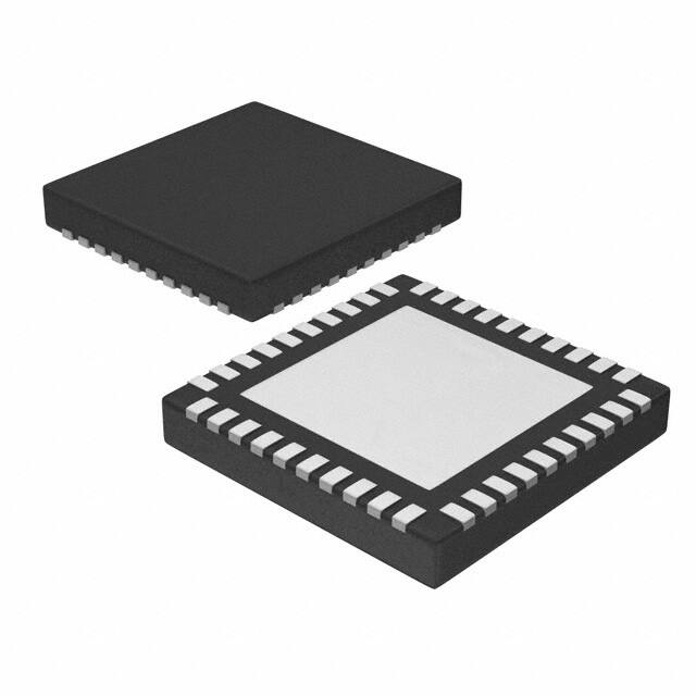


 工商网监
湘ICP备2023018690号
工商网监
湘ICP备2023018690号
